Lapsed, fee not paid5 drawings
Software & Apps · US 8,531,466 B2
Methods for providing realistic animation of autonomous objects through improved animation control signal processing
Systems and methods for creating autonomous agents or objects.
US 8,531,523 B2 · Assignee: TruePosition, Inc. · Inventors: Anderson; Robert J et al.
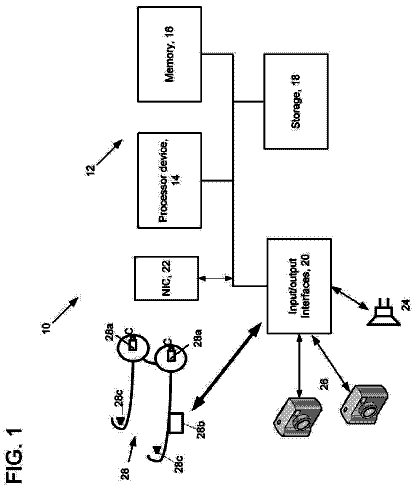
Sheet 1 of 10 from the published document. All sheets in the USPTO PDF
By combining imaging systems with wireless location functionality, a subject's videometric signature can be linked to a public identity, thus enabling continuous surveillance outside or between the coverage area of video surveillance networks. In addition to extending the surveillance coverage area, the combination of computerized video surveillance with wireless location determination may also allow for identification of mobile device users via the existing mobile equipment and user identifiers used in the wireless network.
Since the invention of the closed circuit video camera, real time surveillance of both secure and public areas has been used to augment the efficiency of human guards. The advent of the video cassette recorder (VCR) enabled the archiving of video coverage. In the mid 1970's video technology became cost effective for such public security functions as law enforcement, crowd surveillance, and highway traffic control. The introduction of digital video cameras allowed for software analysis of the video image and during the 1990's facial recognition technology had become sufficiently accurate to be more widely deployed. After the attacks of Sep. 11, 2001, the need for recognition of individuals in secure locations by automated video systems was seen as a public necessity. In May of 2002, the United States Parks Service installed face recognition software on the computerized video surveillance
8 of 10 drawing sheets so far from the published document, cropped to the drawing. Every sheet is in the USPTO PDF.
What the patent claimed, word for word. All of it is now free to use.
The present invention relates generally to methods and apparatus for locating and identifying wireless devices such as those used in analog or digital cellular systems, personal communications systems (PCS), enhanced specialized mobile radios (ESMRs), and other types of wireless voice and data communications systems. More particularly, but not exclusively, the present invention relates to a method for combining information from multiple sensor types to identify and locate wireless device users.
Since the invention of the closed circuit video camera, real time surveillance of both secure and public areas has been used to augment the efficiency of human guards. The advent of the video cassette recorder (VCR) enabled the archiving of video coverage. In the mid 1970's video technology became cost effective for such public security functions as law enforcement, crowd surveillance, and highway traffic control.
The introduction of digital video cameras allowed for software analysis of the video image and during the 1990's facial recognition technology had become sufficiently accurate to be more widely deployed. After the attacks of Sep. 11, 2001, the need for recognition of individuals in secure locations by automated video systems was seen as a public necessity. In May of 2002, the United States Parks Service installed face recognition software on the computerized video surveillance cameras at the Statue of Liberty and Ellis Island.
In addition to facial recognition, video systems may also use other recognition techniques examples of which also include gait recognition, clothing recognition, and two dimensional (2-D) or three dimensional (3-D) image mapping with pattern recognition. These image recognition techniques which use still cameras, video cameras, or other imaging systems may generally be referred to as "videometric" systems. A videometric system may reduce an image or series of images into a digital signature tag. A videometric system may tag and index unidentified subjects to detect repeat visitors. However, identification and tracking of individuals is typically limited to those already identified stored in the video network database. Furthermore, videometric systems are limited by the fields of view provided by the installed imaging systems. A videometric signature is a identification of features allowing for identification of a subject. Much like fingerprints, a videometric signature is unique to an individual, but more subject to change over a long duration.
Technology for locating wireless devices (e.g., cell phones) with high accuracy began to be widely deployed in response to the United States Federal Communications Commission (FCC) Enhanced 9-1-1 Phase II mandate. Wireless location technologies include both network-based and handset based technologies. The network-based high accuracy technologies use the uplink (mobile-to-base station) radio signaling from the handset with Time-of-Arrival (TOA), Time-Difference-of-Arrival (TDOA), and/or Angle of Arrival (AoA) techniques to locate a mobile device. High accuracy location technologies may include the use of a timing beacon systems such as a Global Navigation Satellite System (GNSS), the prime example being the NAVSTAR Global Positioning System (GPS). Use of GNSS signals and signaling from the wireless communications network allow for Assisted GNSS (A-GNSS) which lowers the time needed to generate a position fix over conventional GPS and can increase receiver sensitivity.
Medium accuracy location technologies are sometimes used for localization of transmitters either as a fallback method or in conjunction with a high accuracy localization technique. These techniques include the network-based techniques of cell-ID localization and may include the addition of timing or power ranging Signal-Strength-Measurement (SSM) with calibrated RF fingerprinting (a pattern matching technique). The handset-based medium accuracy technologies include downlink radio signal techniques such as Enhanced Observed Time Difference (E-OTD), Advanced Forward Link Trilateration (AFLT), and Observed Time Difference of Arrival (OTDOA).
Hybridization of location technologies may also be used. Various combinations of U-TDOA, AoA, AFLT, A-GPS, TOA, SSM, and OTDOA have been successfully fielded while other combinations of the high or high/medium accuracy handset and network location techniques have been proposed.
Passive Location using network-based wireless location techniques relies on the monitoring of the radio air interface or WCN links and waiting for the mobile device to execute a network transaction either on the control channel or traffic channel. These network transactions include periodic re-registration, as well as ad hoc events such as call or data connection related events (initiation, termination, handover) and roaming events such as location updating.
Active Location using network-based wireless location techniques relies on cooperation or co-opting of the wireless location system. Cooperative arrangements include polling or auditing via system messaging examples of which include Identity Request, Any_Time_Interrogation (ATI) (as part of the Mobile Terminated Location Request Procedure), Null SMS pinging or simply calling or messaging the mobile in question. Co-opting of the WCN includes use of a control-channel only IMSI catcher base station where idle mobiles devices are momentarily re-registered, a honey-pot base station where both on-call (in session) mobile devices are captured, interrogated and identified, or placing small WCN cells in specific areas with localized paging areas (location areas) to force mobiles to re-register.
For further background information relating to the subject matter described herein, the reader may refer to the following patent applications assigned to TruePosition Inc.: U.S. patent application Ser. No. 11/150,414, "Advanced Triggers for Location-Based Service Applications in a Wireless Location System," filed Jun. 10, 2005; Ser. No. 11/198,996, "Geo fencing in a Wireless Location System," filed Aug. 8, 2005; and Ser. No. 12/428,325, "Network Autonomous Wireless Location System," filed Apr. 22, 2009. Each of these are hereby incorporated by reference in its entirety.
In many operational scenarios, the determined location of a wireless device may not be available. For example, the device may be temporarily shielded from receiving from or transmitting to the wireless network. Furthermore, imaging or videometric systems can only provide identification and tracking functionality when they have a sufficiently unobstructed field of view of the subject. Described herein are various methods and systems for providing a fallback technique. In some embodiments, such systems may be combined to provide seamless or uninterrupted location, tracking, and surveillance services. By combining computerized video surveillance with wireless location functionality, a subject's videometric signature can be more readily linked to a publicly known personal identity, thus enabling continuous surveillance outside or between the coverage areas of video surveillance networks. This seamless surveillance can be real-time or archived for future forensic analysis Linking of videometric signatures to public identities may further allow for automated provisioning of videometric databases. In addition to extending the surveillance coverage area, the combination of computerized video surveillance with wireless location determination may also allow for identification of mobile device users via the existing mobile equipment and user identifiers used in the wireless network.
In one embodiment, a method of tracking a subject associated with a mobile device is disclosed. The method may include receiving image data from an image capture device, receiving identification information and location information for the mobile device, analyzing the received image data, and determining that the received image data is associated with said mobile device based on the analyzed image data and location information associated with said mobile device, and otherwise associating the received image data with the mobile device identified by said location and said identification information.
It should be noted that this summary is provided to introduce a selection of concepts in a simplified form that are further described below. This summary is not intended to identify key features or essential features of the claimed subject matter, nor is it intended to be used as an aid in determining the scope of the claimed subject matter.
In addition to the foregoing, other aspects are described in the claims, drawings, and text forming a part of the present disclosure. It can be appreciated by one of skill in the art that one or more various aspects of the disclosure may include but are not limited to circuitry and/or programming for effecting the herein-referenced aspects of the present disclosure.
The foregoing summary as well as the following detailed description is better understood when read in conjunction with the appended drawings. For the purpose of illustrating the invention, there is shown in the drawings exemplary constructions of the invention; however, the invention is not limited to the specific methods and instrumentalities disclosed in the drawings:
FIG. 1 schematically depicts the major functional components Wireless Communications Network with wireless location capability and a geographically co-located computerized video/photographic surveillance network.
FIG. 2 illustrates opportunities for a location facilitated identification of a subject under video surveillance in an urban area.
FIGS. 3A and 3B illustrate a location facilitated identification of a subject under video surveillance.
FIG. 4 illustrates a location facilitated identification of a subject under video surveillance.
FIG. 5 illustrates a location facilitated surveillance of a subject entering video surveillance coverage through a chokepoint.
FIG. 6 illustrates a location facilitated identification of a subject in a video surveillance coverage area which uses parallax (stereopsis) to estimate the range and motion of a subject.
FIG. 7 illustrates an example of an operational procedure incorporating aspects of the present disclosure.
FIG. 8 illustrates an example of an operational procedure for tracking a subject associated with a mobile device.
FIG. 9 illustrates another example of an operational procedure for tracking a subject associated with a mobile device.
Certain specific details are set forth in the following description and figures to provide a thorough understanding of various embodiments of the invention. Certain well-known details often associated with computing and software technology are not set forth in the following disclosure to avoid unnecessarily obscuring the various embodiments of the invention. Further, those of ordinary skill in the relevant art will understand that they can practice other embodiments of the invention without one or more of the details described below. Finally, while various methods are described with reference to steps and sequences in the following disclosure, the description as such is for providing a clear implementation of embodiments of the invention, and the steps and sequences of steps should not be taken as required to practice this invention.
Described are illustrative embodiments of the present disclosure. First, a detailed overview of the problem is provided, followed by a more detailed description of the disclosed subject matter.
Biometrics refers to methods for uniquely identifying a subject based upon one or more intrinsic physical characteristics. Biometrics may be used as a method of secured access management and access control, and can also be used to identify subjects who are under surveillance. Examples of biometric characteristics can include the shape of the body, fingerprints, face recognition, DNA, hand and palm geometry, and iris recognition.
In a biometric system, the first time a subject uses the biometric system may be referred to as enrollment. During enrollment, biometric information from a subject may be stored. During subsequent identifications, biometric information may be detected and compared with the information stored at the time of enrollment. Such a biometric system may include a sensor for receiving information from the subject and providing the input to the system. The system may also perform pre-processing to enhance or otherwise prepare the input (e.g. removing background noise). The system may then extract features needed for identification. The features may be represented in any form such as a vector or an image with particular properties. The set of features that uniquely identifies a subject may be referred to as a signature.
During enrollment the features may be stored in a storage. During a matching or identification phase, the obtained features may be passed to a matching function that compares the features to other existing sets of features. A set of features may be called a template. In some embodiments, the distance between templates may be estimated using an appropriate algorithm.
A facial recognition system may automatically identify a subject from a digital image or a video frame from a video source. In some embodiments, selected facial features from the image and a facial database may be compared. Some facial recognition algorithms may identify faces by extracting features from an image of the subject's face. For example, a facial recognition algorithm may analyze the relative position, size, and/or shape of the eyes, nose, cheekbones, and jaw. The extracted features may then be used to search for other images with matching features. In other embodiments, a facial recognition algorithm may normalize a collection of facial images and compress the data, saving the data in the image that is useful for facial detection. Some examples of recognition algorithms include Linear Discriminate Analysis, the Hidden Markov model, and the neuronal motivated dynamic link matching. 3-D
A system for capturing and recognizing images may comprise one or more capture devices such as a digital or analog camera with suitable optics for acquiring images, a camera interface for digitizing images, input/output hardware or communication link, and a program for processing images and detecting features of the image.
Photo or video recognition may thus be used for the identification of individuals or subjects via a databased "snapshot" of physical parameters (generally known as a photometric or videometric database entry). However, it is the population of this videometric database that may limit the use of such recognition functionality. For instance, in a video surveillance system overlooking a secure facility such as a railroad yard, a videometric database populated with every employee and potential authorized visitor may be needed to reliably detect a trespasser. The recorded videometric detail of the trespasser can potentially be used to detect intrusion by the same individual a second time, but identification of the trespasser may not be ascertained from the videometric data alone despite the creation of the videometric tag. In some cases, the public identity may not be available from the wireless device (for example in the case of prepaid mobiles), in such cases, the videometric signature may have a public ID associated with it which can then in turn be applied to the previously unidentified wireless device ID. In other cases, the mobile device public ID may not match the known videometric based public ID (in the case of a stolen mobile).
Network-based Wireless Location Systems (WLS) may be used to locate wireless devices from the radio emissions (the uplink radio channel broadcasts) transmitted by the wireless device during control, voice or data sessions between the Wireless Communications Network (WCN) and the wireless device. Accuracy of a network-based WLS may be limited by the short duration, low-power and limited bandwidth of the communications signals, and thus the localization of a particular wireless device in the field-of-view of a video surveillance system from a set of wireless devices may be difficult. Disclosed herein are methods for matching a wireless device and a videometric signature. Once a localized wireless device and a videometric signature have been correlated, retrieval of the wireless identity and thus the public identity of the subject associated with the wireless device can be performed.
The techniques and concepts described herein may apply to time and frequency division multiplexed (TDMA/FDMA) radio communications systems including the widely used GSM and OFDM-based (e.g. IEEE-802.16 "WiMAN", IEEE-802.20 "WIMAX", and 3GPP Long Term Evolution (LTE)) wireless systems, as well as code-division radio communications systems such as CDMA (IS-95, IS-2000) and Universal Mobile Telecommunications System (UTMS), the latter of which is also known as W-CDMA. In addition, short range communications systems such as active or passive Radio Frequency ID (RFID) tags, Bluetooth wireless technology and Ultra-Wideband (UWB) data communications can also be used for proximity location and identification purposes.
The Global System for Mobile Communications (GSM) radio access network and core network is used as an exemplary wireless radio communications system but is not the exclusive environment in which the present disclosure may be implemented.
Identification
The combination of the disparate sensor networks of video and wireless location may provide a non-intrusive method of populating a joint database of videometric signatures via co-location of the subject and the wireless device. A wireless device identity, such as in the case of a subscribed semi-permanent user account, is typically attached to the public identity of an individual. Hence, correlation of the wireless device identity and its wireless location with the estimated or known location of an imaged and parameterized subject may allow for the identification of the subject without the requirement for a pre-existing videometric database entry.
For wide area wireless communications systems, wireless devices include identification of the device and user (e.g., the telephone number, the Electronic Serial Number (ESN), the MIN (Mobile Identification Number), the International Mobile Equipment Identifier (IMEI), the International Mobile Station Identifier (IMSI), the Mobile Station Identifier (MSI), the Temporary Mobile Station Identifier (MSI)), the Mobile Equipment Identifier (MEID), Mobile Station Integrated Services Digital Network number (MS-ISDN)). These identifiers, which vary according to the wireless communications technology (also known as the radio access network technology) used, are necessary to allow the mobile phone to function. These standardized identifiers are available either over the radio signaling interface between the mobile and the Wireless Communications Network (WCN), from within a WCN, or used in signaling between disparate WCNs.
Changes in the wireless identifiers or changes between associated wireless identifiers can be used to trigger the wireless location and identification system. An example of associated identifiers includes the IMEI which identifies a mobile device, and the IMSI which identifies a subscriber module (SIM). Insertion of a new SIM, replacement of the SIM, or replacement of the wireless device all change the association between IMEI and IMSI and thus can be detected by the WLIS and used a location triggering event.
Short-range communications systems such as WiFi (IEEE 802.11), RFID, Bluetooth and Ultra-Wideband may be used for identification and location (via proximity) when the subject carries or is otherwise in close proximity to an equipped device. Such persistent and readable identifiers may allow for a location determination and provide a persistent identifier in place of or in addition to the videometric and/or wireless identifiers.
RFID tags are typically designed to be read by readers in close proximity. Each RFID tag may have a unique identifier and may contain other information (such as passport information or product information). The subject may carry an RFID tag associated with the wireless communications device. Alternatively, the subject may carry or wear an article that includes an RFID tag.
Bluetooth devices may use an inquiry procedure to discover nearby devices or to be discovered by other devices in their locality. The Bluetooth identifier is both persistent and unique to each Bluetooth device.
WiFi Network interface devices typically provide their Media Access Control (MAC) address, also more formally known as the EUI (Extended Unique Identifier). The MAC/EUI is both persistent and unique to each Wireless Network Interface Controller (NIC or WNIC).
Ultra-Wideband (UWB) devices may broadcast their persistent identifiers in response to an interrogation signal. A UWB reader that provides the interrogation signal may receive the identifier and establish a proximity location. In some cases RFID tags may use Ultra-Wideband radios. The various described systems and protocols may have varying degrees of overlap in spectrum and technology.
In the case of non-subscribed wireless mobile phones and devices, electronic identifiers transmitted by the mobile device for registering with the network and placing/receiving calls can nevertheless be correlated to a videometric signature, allowing for persistent surveillance of the subject.
Extended Surveillance
Once a subject has been localized and identified within a video surveillance network, continued surveillance may be enabled outside or between the coverage area of video surveillance networks using mobile device location technologies. These technologies include network-based location systems, mobile-based location techniques, and standardized control functions such as the Mobile Terminated Location Request (MTLR) or the setting of Wireless Intelligent Network (WIN) triggers in the WCN infrastructure.
This seamless surveillance can be performed in real-time or can be archived for future forensic analysis. In addition to extending the surveillance coverage area, the combination of computerized video surveillance with wireless location determination may also allow for identification of mobile phone users via the existing mobile equipment and user identifiers used in the wireless network.
Entry and Exit Geofencing
The Automatic Geo-fencing concept detailed in U.S. patent application Ser. No. 11/198,996 "Geo-Fencing In A Wireless Location System" can be expanded in a coordinated video surveillance and wireless location network.
In an exemplary geo-fencing method, a geo-fenced area may be defined. A set of predefined signaling links of the wireless communications system may be monitored. The method may further include detecting that a mobile device has performed any of the following acts with respect to the geo-fenced area:
enter the geo-fenced area,
exit the geo-fenced area, and
move within a predefined proximity range near the geo-fenced area. A high-accuracy location function may then be triggered in order to determine the geographic location of the mobile device.
Once a subject has been tagged by the videometric/photographic system and identified, the mobile identifiers and videometric signature can be substituted, allowing for automatic, trip-wire geo-fence boundaries to be erected not only on wireless boundaries (such as cell, sector or paging area boundaries), but also on field-of-view boundaries. Both entry and exiting of a subject can be determined by the combined videometric and WLS controlling system.
Wide Area Localization and Histograms
Wide area localization, also known as the collection of mobile identification in an area, was first described in U.S. patent application Ser. No. 11/150,414, "Advanced Triggers for Location-Based Service Applications in a Wireless Location System," filed Jun. 10, 2005. Disclosed was an exemplary method including monitoring a set of signaling links of a wireless communications system, and detecting at least one predefined signaling transaction occurring on at least one of the predefined signaling links. In response to the detection of the at least one predefined network transaction, at least one predefined location service is triggered. The combination of video surveillance networks and wireless location improves on the wide-area concept by allowing creation of statistical data collections such as histograms. The statistical data collections may be based on the subject's location, movements, calling patterns, and co-location with other subjects.
Mobile phones and devices may be identified and located on the basis of presence in a defined geographic area under radio coverage by a sector, a cell or group of cells at a particular time or span of time. This historical location feature may be accomplished by loading an area, defined as a set of cells identifiers, into the passive overlay or integrated Link Monitoring System (LMS). The LMS may then develop a list mobile identifiers (e.g., in GSM the IMSIs, MSISDNs, and associated TMSIs) that initiated a network transaction in the geographic area of interest.
Wide Area Localization may also be configured to generate a running list of mobile identifiers that initiate a future network transaction in the pre-set geographic area of interest.
By adding the photometric or videometric snapshot data database, the wide area localization technique may be improved by allowing for the identification of a subject in a geographic area of interest when the associated mobile(s) are not transmitting. Alternately, the combination of the snapshot and wireless location capabilities may allow for Wide Area Localization outside of the coverage area of a video surveillance network.
Camera and Imaging Alternatives
While many existing video surveillance networks are designed to provide images in the visible spectrum, video and still camera surveillance using ultraviolet or infrared light, millimeter or terahertz radar imaging, or other passive (using existing illumination) or active (using directed illumination or transmitters) techniques can be used to provide the photometric or videometric snapshot data used to uniquely identify subjects under surveillance. In the present disclosure, the terms image capture system and camera may refer to all kinds of imaging systems using active or passive technologies, such as video cameras, still cameras, and radio tomographic imaging (RTI) system.
Identity Correlation Using Other Databases
In some embodiments, the use of a stored database of video to mobile device correlations may be augmented with alternative databases. For example, existing video surveillance networks may use photographs such as mug-shots, passport photos, driver licenses, or identification cards to build a videometric database. Similarly, the disclosed wireless location/identifications system and videometric database combination can be primed with supplementary videometric signatures and mobile identifiers of interest. Furthermore, when performing real time or time delayed forensic analysis of database records, videometric signatures obtained through multiple means can be added to the identification process.
Examples may include camera-equipped automatic teller machines (ATMs) in which both videometric signatures and bank account information can be associated. Another example is data from camera-equipped points of sale (POS) in which credit card information and other public identity data (such as a governmental identity card) may be used.
Any scenario during which identification from a subject must be presented (e.g., an event ticket counter) presents an opportunity for the collection of a public identity, a videometric signature, and a wireless ID if the subject is carrying an active or idle wireless device.
Those skilled in the art will recognize that the disclosed subject matter may be carried out with any type of subject that can carry or otherwise be associated with a mobile device. For example, in an embodiment the subject can be a vehicle. In this embodiment, not only can videometric signatures of a vehicle be used to identify the make, model, and color of the vehicle, but automatic license plate recognition can be used to identify the registry or current renter of the vehicle. Mobile identities of the occupants of the vehicle, obtained using one of the above methods, can be linked to the vehicle ID. Since vehicles are often operated by a single individual such as the owner, the accuracy of the videometric filter may be high. In one embodiment, the correlation of the vehicle ID to the mobile ID can be used to identify a stolen vehicle.
Some video-based automatic number plate recognition systems have the capability to take a photo or video of the occupants of the vehicle. A videometric signature may then be obtained and the data used to link the vehicle to the occupant(s).
Some vehicles may be equipped or installed with embedded wireless communications and wireless location systems. Such installed systems can also be used to identify and locate the vehicle.
Multi-Interval, Multi-Camera Filtering
In some embodiments, multiple cameras may be used. In a multi-camera scenario in which a videometric signature is used to identify a subject, the multiple cameras may be used in one instance or over multiple image captures from one or more cameras to identify a subject. In one embodiment, all mobile devices in the immediate vicinity of the subject may be located and identified. For example, the videometric data may identity the same person at multiple cameras at different times. Location data for all mobile devices in the vicinity of the cameras may be received. Wireless device IDs that correlate strongly to multiple instances of the videometric signature may be considered as a match.
Thus in one embodiment, if the subject of interest is correlated to multiple phones and multiple videometric profiles are collected at multiple locations or multiple times, an association between the mobile phones, videometric profiles and the subject of interest may be assumed.
Velocity Filtering
Another filtering technique for correlating a videometric ID with a wireless identity is use of velocity (heading and speed). The velocity of a subject can be determined through the use of wireless location technologies that use frequency difference of arrival in the determination of a location, detect the Doppler shift in uplink radio signals, or track a series of locations for a subject. A photographic or video system may determine the direction of a tagged subject as the subject moves across the camera's field of view. An approach or movement away from the camera can be detected and measured by a change in perspective size of the captured images. In other embodiments, multiple cameras with overlapping fields of view may be used to determine velocity using, for example, the classical parallax solution for velocity determination. Matching of the videometric determined velocity with the wireless location system determined velocity can be accomplished via a correlation algorithm. Elimination of potential matches may also be accomplished using this method.
Choke Points
In some embodiments, close-in wireless location techniques with vehicular or pedestrian choke points can be used to associate a videometric identity with a mobile identity. Examples of vehicular chokes points can include traffic signals, highway on-ramps, off-ramps, bridges, or toll booths. Examples of pedestrian choke points can include airport entrances, stadium entrances, building entrances, escalators, stairwells, and elevators.
In one embodiment, a wireless device may be used to identify the subject carrying the device under certain scenarios such as at public choke points where high volumes of people pass through a small area throughout the day. Examples can be subway entrances, stadium entrances, any security entrance to a public building or airport, sidewalks, mall entrances, and toll booths. One or more wireless stimulation and detection techniques can be used to determine if a wireless device is passing through the choke point. By communicating with the mobile device, an identity of the device may be determined. The device's identity can be the IMSI/IMEI for a mobile phone, MAC/EUI address for a WiFi device, or RFID information for any RFID device that may be carried or in the vicinity of the subject. For example, an RFID tag may be embedded in a carried product or on an identification badge carried on the person.
The location may be determined as a function of the time and position of sensors and transmitters located, for example, in a security entrance or at a specific point on a sidewalk. Sensors and transmitters may, for example, be included in metal detector or RFID detector sensors, or may be embedded into the natural surroundings as to not be conspicuous (such as in a sidewalk, along a street pole, or along side a building).
Location determination may isolate an individual out of a crowd and determine what wireless devices are on such person and the ID of such devices. A well positioned camera can capture an image of the person, and the image may then be associated with the device(s). The received and analyzed information, including the photo, device info and ID, date, time, location may all be stored in a database for further processing.
The captured image may be processed by a facial recognition product to further determine the subject's identity. In many cases, availability of the device ID and an associated image (with time stamp) may provide valuable information for security and intelligence agencies. The device ID information can then be referenced back to the stored information and the image of the subject may be used for: ID of the person using the device Correlation of multiple detections of the same device, e.g., determining if the device is being passed between different people or always the same person Multiple detections and photos from other sources can be used to increase the probability of a correct face-to-ID match
Facial recognition programs, body and clothing identifiers, and gait recognition techniques can be used to match a subject to a videometric signature. The device ID may then be associated with the videometric signature. In the case of a subject that frequently changes wireless devices, provided that the subject passes through the monitored choke point, information regarding the associated wireless identifiers will be constantly updated and the latest device identifier in use can be determined. Furthermore, a historical timeline of the devices used by the subject can be maintained.
Once the videometric signature is associated to a wireless device, public safety agencies can review the collected historical information to determined where the devices has been located and thus infer that the associated subject was present at the recorded locations.
In one embodiment, a close proximity network of RF sensors and transmitters may be deployed with a computerized video network to cover a throughway. The throughway may be situated such that enhanced videometric signatures may be acquired, such as in a traffic signal or crosswalk. A series of highly directional antennas can be used to create a two dimensional array in space as a cross section of a throughway (e.g., a pedestrian walkway or vehicular motorway). The array may allow relative positioning on the throughway (left, center, right) or the specific point on the sidewalk (e.g., a desired distance from the corner or the street). Such a system may be used to provide improved resolution for correlating videometric signatures to the associated wireless identifiers for cases in which multiple subjects (e.g., pedestrians or vehicles) pass abreast or side by side through the vicinity of interest.
Through predetermined selection and construction of the choke point monitoring system, location and identification of multiple subjects at chokepoints may be enabled. Well-known active wireless identifier systems such as the IMSI catcher, the honey-pot BTS, or specially positioning paging/location area boundaries may be used with choke point deployments.
FIG. 1 illustrates an example videometric system situated within a wireless communications network (WCN) with wireless location capability. The WCN in this illustration is depicted by the wireless base stations 103 and core network server 111 (the Base Station Controller (BSC) and Mobile Switching Center (MSC) using GSM terminology).
The wireless device 101, depicted in the figure as a mobile phone, may be carried by a subject. The subject may be a person, an animal, or a vehicle. The wireless device 101 may be within the field-of-view 102 of at least one camera (e.g., still photograph or video) 106 that provides image data for determining a videometric signature at the linked videometric server 107. The videometric signature may be stored in a videometric database 108. Before or after storage, the developed videometric signature may be analyzed by the videometric server 107 for matches to other prior entries in the videometric database 108.
If no match between videometric signatures are found, then the videometric server 107 may query the wireless location and identification system (WLIS) server 110 to determine if there is a match between the subject's position and that of a wireless device 101 within the geographic vicinity within the camera 106 field-of-view 102. The Wireless Location and Identification system server 110 may be queried for all mobile identifications in the geographic area matching the camera 106 field-of-view 102
Location and identification of the wireless device 101 may be triggered by passive means (see U.S. Pat. Nos. 6,782,264 and 7,167,713 both entitled "Monitoring Of Call Information In A Wireless Location System" and U.S. patent application Ser. No. 11/150,414; "Advanced Triggers For Location-Based Service Applications In A Wireless Location System") or active means (see U.S. patent application Ser. No. 12/428,325; "Network Autonomous Wireless Location System"). The ability to locate the wireless device and identify the device may be a function of a network-based overlay wireless location system, an integrated (with the WCN 111 104) network-based wireless location system, or as part of the WCN infrastructure 111 itself as a software application within the Wireless Intelligent Network (WIN) subsystem that communicates with the WLIS 110. User plane location and identification of the wireless device 101 may be possible although the potential number of wireless devices to be identified, interrogated, and located may cause capacity issues within the WCN. The on-board ability of the wireless device 101 to self-locate (a mobile-based or mobile-assisted location) can limit the accuracy of any user-plane location technique. Once a location and identification is developed for a wireless device, this information may be stored in a database 109 and can be delivered to the videometric server 107 at any time.
As part of this example network, a short range communication access point 105 is shown within the field-of-view 102. If such an RF terminal exists within the field-of-view, additional persistent identifiers may be acquired by interaction with RFID, WiFi, Bluetooth, Ultra-Wideband, or other beacon tagging transceivers by offering connectivity to the tagging transceivers via broadcast. Location of such short range radio transceivers is typically determined by proximity to the terminal although directional antennas can be used to define and/or extend the coverage area.
The description continues in the full USPTO document.
About 5,995 words. The USPTO PDF has it with every drawing.
Fees are due 3.5, 7.5 and 11.5 years after grant. This patent expired on September 10, 2025, so the fee marked "not paid" was the one that went unpaid.
Multi-Sensor Location and Identification
Filed Dec 2009 · published Jun 2011Multi-sensor location and identification
Filed Dec 2009 · granted Sep 2013Earlier publications, parents and continuations. None of them can still be enforced, or this patent would not be listed.
Prior art cited by the examiner or applicant. Useful when you check your own idea for novelty.
Everything on this page comes from the documents linked above.