This application claims priority from Japanese Patent Application No. 2010-220603, filed on Sep. 30, 2010, which is incorporated here into by reference.
Field of the invention
The present invention relates to a method of forming glossy images.
Background of the invention
Photographic images or images as typified by a poster have been prepared by a conventional silver salt photographic system or printing system such as gravure printing but recently are also prepared by an ink jet printer or an electrophotographic image forming apparatus.
In the field of an image forming technology of an electrophotographic system for copiers or printers, for instance, reproduction of minute dot images at a level of 1200 dpi [in which "dpi" refers to the number of dots per inch (2.54 cm)] has become feasible along with development of technologies, such as digitization of an exposure system or reduction of toner particle sizes. Further, there has been developed a technology in which toner images are formed on plural photoreceptor drums, the formed toner images are primarily transferred to an intermediate transfer material to be superimposed and the toner images transferred onto the intermediate transfer material are secondarily transferred to an image support, permitting full color image formation. Thus, formation of full-color images requiring enhanced resolution, such as photographic images, has become feasible through development of image forming technologies, in addition to silver salt photography or conventional printing technology.
Images including a photographic image, such as a poster or the like, often require glossy images. When forming a photographic image by using a toner, for example, a toner image area fixed on an image support such as paper exhibits a certain extent of gloss but the white background region results in little gloss finishing. Such unbalanced finishing in gloss between an image area and a non-image area often vitiates image quality and therefore, a countermeasure has been desired.
From the foregoing background, there was studied a technique to eliminate unevenness in glossiness on the image in which image formation was performed by using a called clear toner having removed colorant components from usual toner. For instance, there was disclosed a technique in which a clear toner was supplied onto an image support having thereon a printed image and subjected to thermal fixing to form a clear toner particle layer, and thereby forming an image exhibiting uniform glossiness on the overall surface (as described in, for example, JP 11-007174 A).
There was also disclosed a technique in which a clear tone particle layer comprised of a clear toner was formed on a printed image prepared by an electrophotographic image forming apparatus, followed by formation of a clear toner layer by using a glossing device to form a glossy image (as described in, for example, JP 2002-341619 A and 2004-258537 A). In this technique, a clear toner particle layer was formed by an electrophotographic image forming apparatus and then, the clear tone particle layer surface was heated with being brought into contact with a belt of a glossing device to melt the clear toner particles and then cooled to form a glossy image.
There was also disclosed a technique of glossy image formation, in which the difference in particle size between a color toner and a clear toner was noted to achieve uniform gloss (as described in, for example, JP 2007-140037 A).
As disclosed above, a clear toner layer was formed on the image layer surface by using a clear toner, rendering it feasible to form a glossy surface with a certain extent of smoothness, whereby a glossy image was obtained.
However, it was proved that problems arose with formation of glossy images by using a clear toner disclosed in the foregoing techniques such that wrapping onto the heating roll of a heat-fixing device of an electrophotographic image forming apparatus occurred or a highly and evenly glossy image was not obtained even when using a glossing device.
Summary of the invention
Accordingly, it is an object of the present invention to provide a method of forming a glossy image in which wrapping onto the heating roll of an oilless type heat-fixing device does not occur even when forming a clear tone particle layer on an image support by using a clear toner in an electrophotographic image formation apparatus and formation of a highly even glossy image (for example, exhibiting a glossiness of at least 80 at a measurement angle of 20.degree.) is stably achieved by passing through an oilless type pressure heating means and a cooling-releasing means of a glossing device.
The foregoing object of the present invention can be realized by the following constitution.
1. Namely, one aspect of the present invention is directed to a glossy image forming method comprising the steps of:
(a) forming a clear toner particle layer with clear toner particles on an image support,
(b) heating and pressing the clear toner particle layer formed on the image support, while bringing the surface of the clear toner particle layer into contact with a belt, and then
(c) cooling the clear toner particle layer to form a clear toner layer,
wherein the clear toner particles contain a binder resin and a releasing agent and exhibit a heat quantity of fusion of not less than 3.0 J/g and not more than 9.5 J/g, and the clear toner particles meeting the following requirement: 0.5.ltoreq.S2/S1.ltoreq.1.0 Wherein, when a clear tone particle is cut so as to pass through its center of gravity, S1 represents a total area of releasing agent domains in a cross section of a clear toner particle and S2 represents a total area of releasing agent domains which exist within a region of 2 .mu.m from the particle surface toward the center of gravity of the particle.
The method of forming a glossy image of the present invention does not cause wrapping onto the heating roll of an oilless type heat-fixing device even when forming a clear tone particle layer on an image support by using a clear toner in an electrophotographic image formation apparatus and formation of a highly even glossy image (for example, exhibiting a glossiness of at least 80 at a measurement angle of 20.degree.) is stably achieved by passing through an oilless type pressure heating means and a cooling and releasing means of a glossing device, whereby superior effects are achieved.
Brief description of the drawings
FIG. 1 shows a schematic view of releasing agent domains existing in the section of a clear tone particle.
FIG. 2 shows a schematic view of releasing agent domains existing in the section within a region of 2 .mu.m from the toner particle surface toward the center of gravity.
FIG. 3 shows a schematic depiction illustrating an image forming method comprising the steps of forming a clear toner particle layer and forming a clear toner layer.
FIG. 4 is a schematic view of an example of an image forming apparatus capable of forming a printed image provided with a clear toner particle layer on the overall surface of an image support simultaneously with formation of a color toner image.
FIG. 5 illustrates a schematic view of an exemplified glossing device capable of forming a glossy image.
FIG. 6 shows a schematic view of an example of an image forming apparatus shown in FIG. 4 and further provided with a glossing device, as shown in FIG. 5.
FIG. 7 shows a schematic view of an example of an image forming apparatus, in which the heat-fixing device of the image forming apparatus 2 shown in FIG. 4 is replaced by a glossing device, as shown in FIG. 5.
Detailed description of the invention
There was studied by the inventors a method of forming a glossy image in which wrapping onto the heating roll of an oilless type heat-fixing device was not caused even when forming a clear tone particle layer on an image support by using a clear toner in an electrophotographic image formation apparatus and formation of a highly even glossy image (for example, exhibiting a glossiness of at least 80 at a measurement angle of 20.degree.) was stably achieved by passing through an oilless type pressure heating means and a cooling-releasing means of a glossing device.
As a result of extensive study, it was proved that specification of a heat quantity of fusion and the position of releasing agent domains existing within a clear toner particle inhibited occurrence of wrapping onto the heating roll of an oilless type heat-fixing device, and passing through an oilless type pressure heating means and a cooling-releasing means of a glossing device rendered it feasible to obtain a highly even glossy image.
Specifically, the clear toner contains a hinder resin and a releasing agent and its heat quantity of fusion (.DELTA.H) is not less than 3.0 J/g and not more than 9.5 .mu.g at the time of temperature rise in a DSC curve determined in differential scanning calorimetry, and the total area (S1) of releasing agent domains in the section of a clear toner particle and the total area (S2) of releasing agent domains existing within a region of 2 .mu.m in a direction toward the center of gravity from the particle surface meet the following requirement: 0.5.ltoreq.S2/S1<1.0.
The use of a clear toner related to the present invention does not cause wrapping onto the heating roll of an oilless type heat-fixing device and a highly even gloss image can be obtained by passage through an oilless type pressure heating means and a cooling-releasing means of a glossing device (or glossiness-providing device).
The reason for a highly even-glossy image obtained by passage through an oilless type pressure heating means and a cooling-releasing means of a glossing device is presumed to be that the quantity of heat which is lost in fusion of a releasing agent as an endothermic reaction is lessened and the heat quantity which is externally supplied is effectively used for softening of clear toner particles, and thereby, a clear toner particle layer is softened by the pressure-heating means to form the smoothened surface of the clear toner layer by the belt surface of the cooling-releasing means, as if it is pressed by a domestic iron, whereby a highly glossy image is achieved.
The reason for prevention of wrapping onto the heating roll of an oilless type heat-fixing device is also presumed to be that since releasing agent domains are allowed to exist near the clear toner particle surface, the releasing agent effectively bleeds out onto the clear toner particle surface to achieve releasing effect when thermally fixing a toner on the image support and further, even when fixing at high-speed.
First, there will be described definition of the terms used in the present invention.
Glossy Image:
The glossy image defined in the present invention refers to an image provided on an image support, of which all or part of the surface is covered with a clear toner layer.
Image Support:
An image support defined in the present invention refers to a support used to form a printed image and a clear toner layer.
The image support usable in the present invention may be any one which can form a toner image by using an electrophotographic image forming apparatus installed with an oilless heat-fixing device and can also hold a clear toner layer on the toner image, and the image support may employ one commonly known in the art. Examples of such a commonly known image support include plain paper including thin paper and thick paper, fine-quality paper, printing paper such as art paper or coated paper, paper used for commercially available post cards and plastic film used for OHP.
Image:
The image defined in the present invention refers to one which makes a form as a medium providing information to a user, for example, like a text image or a picture image. Namely, the image refers to not only an area having a toner or ink on an image support, a so-called image area but also an area including a non-image area, a so-called white background. Thus, the image defined in the present invention refers to an image area formed of a toner or ink and an area including a non-image area in which neither toner nor ink exists, that is, a white background.
In the present invention, methods of preparing an image before forming a clear toner particle layer are not specifically limited and include commonly known image forming methods, such as an electrophotographic system, a printing system, an ink-jet system, and a silver salt photography system.
Clear Toner:
The clear toner cited in the present invention refers to a toner not containing a coloring agent exhibiting color through an action of light absorption or light scattering (for example, a coloring pigment, a coloring dye, black carbon particles and a black magnetic powder). The clear toner is usually not colored and transparent but one or another clear toner exhibits lowered transparency due to the kind or content of a binder resin, wax, or additive, but refers to one not containing any colorant in the present invention.
In the present invention, the clear toner refers to an aggregate of clear toner particles.
Clear Toner Particle Layer:
The clear toner particle layer cited in the present invention refers to a layer formed on an image support and composed of clear toner particles which are supplied from the clear toner particle layer-forming section of an electrophotographic image forming apparatus.
Clear Toner Layer:
The clear toner layer cited in the present invention refers to a layer obtained by melting a clear toner particle layer formed on an image support with pressing and heating, followed by cooling. The clear toner layer is formed preferably by using a clear toner in an amount of not less than 2 g/m.sup.2 and not more than 15 g/m.sup.2. A clear toner layer formed of an amount falling within such a range can form a highly even-glossy image and is also superior in abrasion resistance.
Image Glossiness:
The glossiness of an image, cited in the present invention is a value determined when quantitatively measuring the extent of reflection on the image surface while the image surface is exposed to light under prescribed conditions.
The glossiness of an image is determined in the manner that an area of a clear toner layer on an image is measured randomly at five point by a glossmeter (GMX-203, produced by Murakami Shikisai-gijutsu Kenkyuusho Co., Ltd.) at an incident angle of 20.degree. in accordance with JIS Z 8741 1997, and the average value thereof is defined as glossiness of the image.
In the following, the present invention will be described in detail.
Clear Toner:
It is preferred for formation of a glossy image to use a toner of a reduced releasing agent content and a lessened heat quantity of fusion. However, reduction of releasing agent content easily causes wrapping onto the heating roll of an electrophotographic image forming apparatus or on the belt of a glossing device.
It was found by the inventors of the present invention that the use of a toner in which the location of a releasing agent within a toner particle and the heat quantity of fusion were specified, rendered it feasible to prevent an image support from being wrapped onto an oil-less type heating roll or a belt.
The clear toner used in the present invention is featured in that the clear toner exhibits a heat quantity of fusion of not less than 3.0 J/g and not more than 9.5 J/g at the time of temperature rise in a differential scanning calorimetry (DSC) curve determined by a differential scanning calorimeter and the clear toner particles meet the following requirement: 0.5.ltoreq.S2/S1<1.0 wherein S1 represents the total area of releasing agent domains in the section of a clear toner particle and S2 represents the total area of releasing agent domains which exist within a region of 2 .mu.m from the particle surface toward the center of gravity.
The clear toner exhibiting a heat quantity of fusion of not less than 3.0 J/g and not more than 9.5 J/g can be prepared by reducing the releasing agent content and the use of a releasing agent with a low heat quantity of fusion.
A heat quantity of fusion of a clear toner of 3.0 J/g or more renders it feasible to prevent wrapping onto a heating roller. Further, a heat quantity of fusion of a clear toner of 3.0 J/g or more renders it feasible to achieve a highly and uniformly glossy image.
The heat quantity of fusion (.DELTA.H) refers to a heat quantity of fusion at the time of temperature rise in a differential scanning calorimetry (DSC) curve determined by using a differential scanning calorimeter and is measured by using DSC-7 differential scanning calorimeter (produced by Perkin Elmer Inc.).
The measurement is conducted as follows. A clear toner of 4.5-5.0 mg is precisely weighed to two places of decimals, sealed into an aluminum pan (Kit No. 0219-0041) and set into a DSC-7 sample holder. An empty aluminum pan is used as a reference. The temperature is controlled through heating-cooling-heating at a temperature-rising rate of 10.degree. C./min and a temperature-lowering rate of 10.degree. C./min in the range of 0 to 200.degree. C.
The heat quantity of fusion of a clear toner is represented as an energy quantity (J/g) calculated from an area sectioned by an endothermic peak and the base line in the region except for the endothemlic peak of a resin.
Releasing Agent Domain:
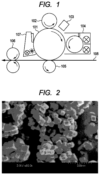
A clear toner used in the present invention exhibits a structure in which releasing agent domains are formed in a clear toner particle. The releasing agent domains refer to islands of a sea-island structure when observing the section of a clear toner particle and correspond to the region designated by plural circles, as shown in FIG. 1 and FIG. 2.
In the present invention, releasing agent domains allowed to exist in the vicinity of the surface of a clear toner particle so that the releasing agent easily bleeds out on the surface of the clear toner particle, whereby a maximum releasing effect is achieved by a small amount of a releasing agent.
One feature of a clear toner used in the present invention is that clear toner particles are allowed to exist so that S2/S1 is not less than 0.5 and not more than 1.0, in which S1 represents the total area of releasing agent domains in the section of a clear toner particle and S2 represents the total area of releasing agent domains which exist within a region of 2 .mu.m from the particle surface toward the center of gravity.
A clear toner exhibiting S2/S1 of not less than 0.5 can be obtained by allowing a releasing agent to be contained only in the shell layer of a clear toner particle of a core/shell structure, or by using a highly polar releasing agent and allowing the releasing agent to be oriented toward the surface of a clear toner particle.
FIG. 1 shows a schematic view of releasing agent domains existing in the section when cutting a clear tone particle so as to pass through its center of gravity. In FIG. 1, the numeral 1 designates the section of a clear particle which is cut so as to pass through the center of gravity and designations, S.sub.1-1, S.sub.1-2, S.sub.1-3, S.sub.1-4, S.sub.1-5, . . . S.sub.1-n, each shows a releasing agent domain.
When a clear tone particle is cut so as to pass through its center of gravity, FIG. 2 shows a schematic view of releasing agent domains existing in the section within a region of 2 .mu.m from the toner particle surface toward the center of gravity.
In FIG. 2, the numeral 1 designates the section of a clear particle which is cut so that the cut passes through the center of gravity, the numeral 2 designates a line drawn at a distance of 2 .mu.m from the surface toward the center of gravity, the numeral 3 designates a distance of 2 .mu.m from the surface of the clear toner particle toward the center of gravity, and designations, S.sub.2-1, S.sub.2-2, S.sub.2-3, . . . S.sub.1-n show releasing agent domains existing within a region of 2 .mu.m from the toner particle surface toward the center of gravity.
The total area (S1) of releasing agent domains existing on the clear toner particle section is the sum of S.sub.1-1, S.sub.1-2, S.sub.1-3, S.sub.1-4, S.sub.1-5, . . . S.sub.1-n.
The total area (S2) of releasing agent domains existing within a region of 2 .mu.m from the clear toner particle surface toward the center of gravity is the sum of S.sub.2-1, S.sub.2-2, S.sub.2-3, . . . S.sub.1-n. In the case of a domains existing on the boundary line, only an area falling within the boundary line is counted.
The total area (S1) of releasing agent domains existing on the clear toner particle cross-section and the total area (S2) of releasing agent domains existing within a region of 2 .mu.m from the clear toner particle surface toward the center of gravity are those measured from an electron micrograph of the sectional layer of a clear toner particle, photographed by a transparent electron microscope. There are usable commercially available transmission electron microscopes, and including, for example, LEM-2000 (produced by Topcon Co., Ltd.) and JEM-2000 FX (produced by Nippon Denshi Co., Ltd.).
Specifically, after dispersing clear toner particles sufficiently in a curable acryl resin, the resin is cured so as burry the particles within the cured resin, and from the obtained block, a thin film sample is sliced by using a microtome installed with a diamond knife-edge. The thus sliced sample is optionally dyed with a stain using ruthenium (VIII) oxide and osmium (VIII) oxide singly or in combination, whereby the resin portion or releasing agent domains are dyed so as to distinguish the resin portion from the releasing agent domains. Thereafter, photographing is performed by a transparent electron microscope at a magnification (approximately 10,000-fold) by using a transmission electron microscope (FEM).
The total are of releasing agent domains (S1) and the total are of releasing agent domains (S2) can be determined by subjecting the thus photographed image data to image processing by using, for example, LUZEX F (produced by NIRECO Co., Ltd.). An average value of S1 and an average value of S2 are calculated with respect to 100 clear toner particles in accordance with the foregoing method and the ratio of S2 to S1 (S2/S1) is determined from these average values.
Volume-Based Median Diameter (D.sub.50):
The volume-based median diameter (D.sub.50) is preferably not less than 5 .mu.m and not more than 12 .mu.m.
The volume-based median diameter (D.sub.50) can be determined by using a measurement apparatus in which a Coulter Multisizer 3 (produced by Beckmann Coulter Co.) is connected to a computer system installed with software for data processing (Software V3. 51).
Specifically, a clear toner in an amount of 0.02 g is treated with a 20 ml surfactant solution (in which a neutral detergent containing a surfactant component is diluted 10 times with pure water) and then subjected to ultrasonic dispersion for 1 min. to prepare a toner dispersion. The toner dispersion is introduced by a pipette into a beaker containing ISOTON II (produced by Beckman Coulter Co.), placed in a sample stand until reaching a measured concentration of 5 to 10% and the analyzer count is set to 25000 particles. Using Coulter Multisizer 3 of an aperture diameter of 50 .mu.m, a measurement range 1.0 to 30 .mu.m is divided into 256 sections to calculate frequency and the particle size of a volume fraction of 50%, integrated from the larger side, is determined as a volume-based median diameter (D.sub.50).
Material Constituting Clear Toner:
A clear toner used in the present invention contains at least a resin and a releasing agent.
Releasing Agent:
In the present invention, there is preferably used a releasing agent which effectively prevents wrapping onto a heating roll or belt, exhibits a small heat of fusion and is partially compatible with a resin.
Specific examples of a releasing agent include a low molecular weight polyolefin such as polyethylene, polypropylene or polybutene; silicones exhibiting a softening point upon heating; a carboxylic acid amide such as oleic acid amide, erucamide, or ricinolic acid amide; plant wax such as carnauba wax or rice wax; animal wax such as beeswax; mineral/petroleum wax such as montanic acid wax, ceresin, paraffin, or Fisher Tropsch wax. Preferred examples include esters of a long chain alkyl mono-alcohol having 12 to 30 carbon atoms and a higher carboxylic acid having 12 to 30 carbons, such as stearyl stearate, palmityl palmitate, and behenyl behenate; esters formed of a polyvalent carboxylic acid and a long chain alkyl alcohol having 12 to 30 carbons, such as dibehenyl itaconate, distearyl maleate and tristearyl aconitate; esters formed of a polyvalent alcohol and a higher carboxylic acid, such as tristearic acid glyceride, tribehenic acid glyceride, pentaerythritol tetrabehenate, and pentaerythritol stearate; esters of a higher carboxylic acid having 12 to 30 carbons and a polyvalent alcohol, such as tetrastearic acid diglyceride, tetrabehenic acid diglyceride, hexabehenic acid triglyceride, dekastearic acid ecaglyceride, and dipentaerythritol hexastearate; sorbitan higher carboxylic acid esters such as sorbitan tristearate, sorbitan tribehenate and sorbitan trioleate; and cholesterol carboxylic acid esters such as cholesterol stearate, cholesterol behenate, and cholesterol oleate. These are chosen depending on melting point, fusion viscosity or heat quantity of fusion.
A releasing agent used in the invention preferably is one which exhibits a heat quantity of fusion of not less than 80 J/g and not more than 250 J/g. The use of a releasing agent exhibiting a fusion heat quantity falling within this range makes it easy to obtain a clear toner exhibiting a fusion heat quantity of not less than 3.0 J/g and not more than 9.5 J/g. The fusion heat quantity of a releasing agent can be determined in a manner similar to the clear toner.
The amount of a releasing agent contained in a clear toner is preferably not less than 0.5% by mass and not more than 5.0% by mass of the total mass of the clear toner.
A releasing agent used in the invention preferably exhibits a melting point of not less than 50.degree. C. and not more than 100.degree. C. The use of a releasing agent exhibiting a melting point falling within this range effectively prevents wrapping onto a heating roll or belt.
Resin:
The clear toner used in the present invention preferably has a structure comprising a shell layer containing a releasing agent and provided on the outside of a core portion not containing a releasing agent.
A resin constituting the core portion is preferably formed of a styrene-acryl resin in terms of fixability.
Styrene monomers and acrylic acids which are capable of forming a styrene acryl resin are shown below, but styrene monomers and acrylic acid monomers usable in the present invention are by no means limited to these.
Specific examples of a styrene monomer include styrene, o-methylstyrene, m-methylstyrene, p-methylstyrene, .alpha.-methylstyrene, p-phenylstyrene, p-ethylstyrene, 2,4-dimethylstyrene, p-tert-butylstyrene, p-n-buthylstyrene, p-n-octylstyrene, p-n-nonylstyrene, p-n-decylstyrene, and p-n-dodecylstyrene.
An acrylic acid ester monomer is typified by an acrylic acid ester monomer and a methacrylic acid ester monomer, as below. Examples of an acrylic acid ester monomer include methyl acrylate, ethyl acrylate, isopropyl acrylate, n-butyl acrylate, t-butyl acrylate, iso-butyl acrylate, n-octyl acrylate, 2-ethylhexyl acrylate, stearyl acrylate, lauryl acrylate and phenyl acrylate.
Examples of a methacrylic acid ester include methyl methacrylate, ethyl methacrylate, n-butyl methacrylate, isopropyl methacrylate, isobutyl methacrylate, t-butyl methacrylate, n-octyl methacrylate, 2-ethylhexyl methacrylate, stearyl methacrylate, lauryl methacrylate, phenyl methacrylate, diethylaminoethyl methacrylate, and dimethylaminoethyl methacrylate.
These acrylic acid ester monomers and methacrylic acid ester monomers may be used singly or in combination of two or more of them. Namely, it is feasible to form a copolymer by use of a styrene monomer and two or more acrylic acid ester monomers, to form a copolymer by use of a styrene monomer and two or more methacrylic acid ester monomers or to form a copolymer by use of a styrene monomer and at least an acrylic acid ester monomer and a methacrylic acid ester monomer.
A resin forming a shell layer preferably exhibits a softening point higher than that of a resin forming the core portion, but there is no problem in resins exhibiting identical thermal characteristics.
Next, there will be described preparation of a clear toner usable in the present invention.
Preparation of Clear Toner:
Preparation of a Clear Toner Usable in the Present Invention May Employ Various Methods and includes a preparation method comprising a step of allowing resin particles used for the core portion to be aggregated to form a core portion and a step of allowing resin particles used for a shell layer to be attached to the surface of the core portion to form clear toner particles having a core/shell structure.
A preparation method of a clear toner is described below with reference to an example.
A clear toner used in the present invention is prepared by a process comprising the steps of:
polymerizing a polymerizable monomer to prepare a dispersion of resin particles used for a core portion,
polymerizing a polymerizable monomer to prepare a dispersion of resin particles used for a shell portion,
allowing the resin particles used for a core portion to be aggregated to form core portions,
ripening the core portions with a heat energy to control the shape thereof,
adding a dispersion of resin particles used for a shell layer and a releasing agent dispersion to a dispersion of the core portions and allowing the resin particles used for a shell layer and the releasing agent to be aggregated and fused to form a shell layer, and forming particles of a core/shell structure,
ripening the particles of a core/shell structure with heat energy to control the shapes of the particles of a core/shell structure, and preparing a dispersion of toner parent particle,
cooling the dispersion of toner parent particles and then separating the toner parent particles through solid-liquid separation to remove a surfactant or the like from the toner parent particles (washing step),
drying the thus washed toner parent particle (drying step), and
adding external additives to the dried particles as needed.
In the preparation of a clear toner used in the present invention, first, resin particles for a core are aggregated and fused to form a core portion. Then, a dispersion of resin particles used for a shell layer and a releasing agent dispersion are added to allow the resin particles used for a shell layer and the releasing agent to be aggregated and fused onto the surface of the core portion to form a shell layer, whereby toner parent particles having a core/shell structure of covering the surface of the core portion with a shell layer containing the releasing agent.
Clear toner used in the present invention is preferably comprised of clear toner particles formed of a shell of a thin even layer and having a uniform small shape. Clear toner particles of such a structure and a shape are prepared in the manner that core particles of a uniform size and shape are formed and further thereto, resin particles to form a shell layer are added to perform shelling. When performing shelling, the shape of toner particles is finally controlled to form an appropriate shape and to achieve this, it is most important to prepare core particles of uniform size and shape. Accordingly, on the surfaces of such core particles are uniformly attached resin particles used for a shell layer, leading to preparation of clear toner particles with a uniformly thick shell layer.
The shape of such core particles can be controlled by control of a heating temperature in the step of aggregation and fusion and control of heating temperature and time in the step of ripening. In particular, it is most effective to control the time in the ripening stage. Namely, the ripening step is intended to control the circularity of a core particle, so that the intended circularity is achieved by control of the time.
A shell layer constituting a clear toner particle is formed preferably in the manner that a releasing agent component is dissolved or dispersed in a dispersion of a polymerizable monomer to form a resin and further mechanically dispersed in a fine particulate form, followed by polymerization of the polymerizable monomer by a process of mini-emulsion polymerization to form composite resin particles, and thus formed resin particles are subjected to salting-out and fusion. When dissolving a releasing agent component in the polymerizable monomer, the releasing agent component may be dissolved through solution or fusion.
In the following, there will be described a surfactant, a polymerization initiator and external additives which are employed in the preparation of a clear toner used in the present invention.
Surfactant:
When performing polymerization of a polymerizable monomer, as described above, the polymerizable monomer is required to be dispersed in an aqueous medium in the form of oil-droplets by using a surfactant. Such a surfactant is not specifically restricted but ionic surfactants described below are preferred.
Examples of an ionic surfactant include a sulfonate (e.g., sodium dodecylbenzene sulfonate, sodium aryl alkyl polyether sulfonate, sodium 3,3-disulfonediphenyl urea-4,4-diazo-bis-amino-8-naphthol-6-sulfonate, o-carboxybenzene-azo-dimethylaniline, sodium 2,2,5,5-tetramethyl-triphenylmethane-4,4-diazo-bis-.beta.-naphthol-6-sulf- onate), a sulfuric acid ester salt (e.g., sodium dodecylsulfate, sodium tetradecylsulfate, sodium pentadecylsulfate, sodium octylsulfate), and a carboxylate (e.g., sodium oleate, sodium laurate, sodium caprate, sodium caprylate, sodium caproate, potassium stearate, calcium oleate).
There are also usable nonionic surfactants. Specific examples thereof include polyethylene oxide, polypropylene oxide, a combination of polyethylene oxide and polypropylene oxide, an ester of polyethylene glycol and a higher fatty acid, an alkylphenol polyethylene oxide, an ester of a higher fatty acid and polypropylene glycol, and a sorbitan ester.
Polymerization Initiator:
In the present invention, a resin constituting a core particle and a shell layer comprises a styrene-acryl copolymer resin which is formed through radical polymerization of a styrene monomer and an acrylic acid ester monomer. Commonly known oil-soluble or aqueous-soluble polymerization initiators are usable in formation of such a styrene-acryl copolymer resin. Examples of such an oil-soluble polymerization initiator include azo- or diazo-type polymerization initiators and peroxide polymerization initiators.
External Additive:
External additives are not specifically restricted and various kinds of inorganic particles, organic particles and lubricants. Preferred examples of inorganic particles include inorganic oxide particles of silica, titania, alumina or the like. Such inorganic particles are preferably subjected to a hydrophobilization treatment.
An external additive is added preferably in an amount of not less than 0.1% by mass and not more than 5.0% by mass of the toner, and more preferably, not less than 0.5% by mass and not more than 4.0% by mass. External additives may be added singly or in combination of them.
Developer:
The clear toner used in the present invention is usable as a single component clear toner developer or a two-component clear toner developer. In cases when used as a two-component clear toner developer by mixing it with a carrier, magnetic particles as such a carrier may employ commonly known materials, as typified by iron-containing magnetic particles such as iron, ferrite or magnetite, of which ferrite particles or magnetite particles are specifically preferred. The volume average particle size of the foregoing magnetic particles preferably is not less than 15 .mu.m and not more than 100 .mu.m, and more preferably, not less than 20 .mu.m and not more than 80 .mu.m. The volume average particle size of a earner can be measured by a laser diffraction type particle size distribution measurement device (HELOS, produced by SYMPATEC Limited Co.).
A carrier is preferably a coating carrier in which a magnetic particle is covered with a resin, or a so-called resin dispersion type carrier in which magnetic particles are dispersed in a resin. The resin used for coating is not specifically limited and examples thereof include a olefin resin, a styrene resin, a styrene-acryl resin, a silicone resin, an ester type resin and a fluorine-containing polymer resin. A resin to constitute a resin dispersion type carrier also is not specifically restricted and examples thereof include a styrene-acryl resin, a polyester resin, a fluoro-resin and a phenol resin.
The mixing ratio of carrier to clear toner by mass (carrier:clear toner) is preferably in the range of 1:1 to 50:1.
Next, there will be described a formation method of a glossy image. In the glossy image formation method of the present invention, a printed image having a clear toner particle layer is formed on an image support by using a clear toner and the formed printed image is heated and pressured, and then cooled to prepare a glossy image provided with a clear toner layer.
FIG. 3 shows a schematic depiction illustrating an image forming method comprising the steps of forming a clear toner particle layer and forming a clear toner layer.
In FIG. 3, "P" designates an image support, "A" designates a printed image, "B" designates a clear toner particle layer, "C" designates a glossy image, "D" designates a clear toner layer, "T" designates a toner image, the numeral 1 represents a step of forming a clear toner particle layer and the numeral 2 represents a step of forming a clear toner layer.
The schematic depiction shown in FIG. 3 illustrates a glossy image forming method comprising the steps of forming a toner image (T) on an image support (P) by using an oilless type image forming apparatus, then, supplying a clear toner to the whole surface of the image support to form a printed image (A) provided with a clear toner particle layer (B), then, melting the clear toner particle layer (B), followed by being cooled to prepare a glossy image (C) provided with a smooth clear toner layer (D).
In the present invention, the oilless type image forming apparatus refers to an apparatus installed with a means for coating an oil (for example, silicone oil) onto the surface of a heating roll or a belt to improve releasability of an image support from the heating roll, or releasability of the image support from a belt of a glossing device. The use of an oil often causes glare due to the oil, resulting in uneven gloss.
Formation of Printed Image:
A printed image can be formed by providing a clear toner particle layer onto a toner image formed by an electrophotographic process, or by providing a clear toner particle layer onto a print printed by a printing method or the like.
In the following, there will be described a method of forming a printed image by providing a clear toner particle layer to a print prepared by an electrophotographic apparatus.
FIG. 4 is a schematic view of an example of an image forming apparatus capable of forming a printed image provided with a clear toner particle layer on the overall surface of an image support simultaneously with formation of a color toner image.
The description continues in the full USPTO document.
 Lapsed, fee not paid1 drawing