Patent Yard Sign in
Lapsed, fee not paid

Ball transfer unit

US 8,529,131 B2 · Assignee: Shenzhen China Star Optoelectronics Technology Co., Ltd. · Inventors: Deng; Hongtao

USPTO PDF

Overview

Sheet 1 of 4 from the published document. All sheets in the USPTO PDF

Abstract From the patent

The present invention provides a ball transfer unit, which includes: a main body, a first rotating body, and a plurality of second rotating bodies arranged between the main body and the first rotating body. The main body has an end forming a receiving chamber and thus forming a receiving chamber sidewall. The second rotating bodies are rotatably arranged on the receiving chamber sidewall. The main body forms an air entrance passage in communication with the receiving chamber. The receiving chamber sidewall extends out to form a bearing section corresponding to the air entrance passage. The bearing section has a side surface in which air outlet ports are formed. The ball transfer unit of the present invention prevents powder dusts from falling therein, ensures smooth operation of the ball transfer unit, and extends the lifespan.

Why it's free to use

  • The USPTO Official Gazette of November 4, 2025 lists it as expired on September 10, 2025 for an unpaid maintenance fee.
  • It isn't on any reinstatement notice published since.
  • Its 1 US relative has also lapsed, expired or never issued.
  • We check US rights only. Check foreign counterparts before selling abroad.
FiledDecember 7, 2011
GrantedSeptember 10, 2013
Expired (fee)September 10, 2025
Application number13/381942
Classification (CPC)F16C29/046 +1 more
Length4 claims · 7 pages

Drawings 4

1 of 4 drawing sheets so far from the published document, cropped to the drawing. Every sheet is in the USPTO PDF.

Figures as described

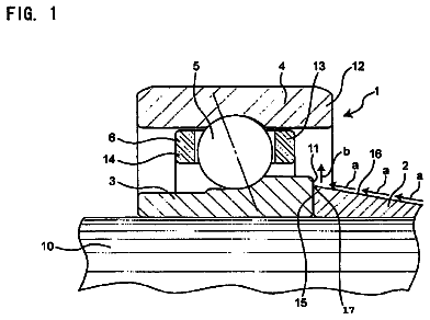
  • FIG. 1 is a schematic view showing a conventional ball transfer unit
  • FIG. 2 is a perspective view showing a ball transfer unit according to the present invention
  • FIG. 3 is a cross-sectional view of the ball transfer unit taken along line 3-3 of FIG. 2
  • FIG. 4 is an enlarged view of a circled portion that is marked "4" in FIG. 3
  • FIG. 5 is a cross-sectional view of the ball transfer unit taken along line 5-5 of FIG. 2

Claims 4 total, 1 independent

What the patent claimed, word for word. All of it is now free to use.

  1. 1
    Independent claimA ball transfer unit, which comprises a main body, a first rotating body, and a plurality of second rotating bodies arranged between the main body and the first rotating body, the main body having an end forming a receiving chamber and thus forming a receiving chamber sidewall, the second rotating bodies being rotatably arranged on the receiving chamber sidewall, the main body forming an air entrance passage in communication with the receiving chamber for supplying an airflow to the receiving chamber, the receiving chamber sidewall extending out to form a bearing section that surrounds and delimits the air entrance passage, the bearing section having a side surface in which air outlet ports are formed, the receiving chamber sidewall having a free end forming a stop rim, whereby the second rotating bodies are confined between the stop rim and the bearing section.
  2. 2
    The ball transfer unit as claimed in claim 1, wherein the air entrance passage has an end located in a side surface of the main body and an opposite end arranged in a center of the receiving chamber.
  3. 3
    The ball transfer unit as claimed in claim 1, wherein the air output ports are uniformly arranged in the side surface of the bearing section.
  4. 4
    The ball transfer unit as claimed in claim 3, wherein the air outlet ports comprise through holes or recesses.

Claim map

Independent claims stand on their own. The others add detail to the claim they name.

Claim 13 claims build on it

Description

Background of the invention

1. Field of the invention

The present invention relates to a ball transfer unit, and in particular to a ball transfer unit comprising an air entrance passage.

2. The Related Arts

As shown in FIG. 1, a conventional ball transfer unit comprises: a main body 100, a first rotating body 200, and a plurality of second rotating bodies 300 arranged between the main body 100 and the first rotating body 200. The main body 100 has an end forming a receiving chamber 110 and thus forming a receiving chamber sidewall 112. The second rotating bodies 300 are rotatably arranged on the receiving chamber sidewall 112. The main body 100 has an opposite end that forms a connection section 120. The receiving chamber sidewall 112 has a free end forming a stop rim 114 extending to each other for retaining and supporting the second rotating bodies 300. When the ball transfer unit is used in an application where there are a lot of powder dusts, such as a glass substrate cutting machine, the powder dusts may fall into the tiny gap between the first rotating body 200 and the stop rim 114 and converts rolling friction between the first rotating body 200 and the second rotating bodies 300 into sliding friction, thereby increasing the friction force therebetween, affecting the performance of the ball transfer unit and shortening the lifespan of the ball transfer unit.

Summary of the invention

An objective of the present invention is to provide a ball transfer unit, which prevents powder dusts from falling therein, ensures the performance of operation, and extends the lifespan.

To achieve the objective, the present invention provides a ball transfer unit, which comprises: a main body, a first rotating body, and a plurality of second rotating bodies arranged between the main body and the first rotating body. The main body has an end forming a receiving chamber and thus forming a receiving chamber sidewall. The second rotating bodies are rotatably arranged on the receiving chamber sidewall. The main body forms an air entrance passage in communication with the receiving chamber. The receiving chamber sidewall extends out to form a bearing section corresponding to the air entrance passage. The bearing section having a side surface in which air outlet ports are formed.

The air entrance passage has an end located in a side surface of the main body and an opposite end arranged in a center of the receiving chamber.

The air outlet ports are uniformly arranged in the side surface of the bearing section.

The air outlet pots comprise through holes or recesses.

The efficacies of the present invention are as follows: The present invention provides a ball transfer unit, which forms an air entrance passage in communication with a receiving chamber. The air entrance passage draws in air to blow off foreign objects, such as powder dusts, present on a receiving chamber sidewall to thereby ensure smooth operation of the ball transfer unit and extend the lifespan.

For better understanding of the features and technical contents of the present invention, reference will be made to the following detailed description of the present invention and the attached drawings. However, the drawings are provided for the purposes of reference and illustration and are not intended to impose undue limitations to the present invention.

Brief description of the drawings

The technical solution, as well as beneficial advantages, will be apparent from the following detailed description of an embodiment of the present invention, with reference to the attached drawings. In the drawings:

FIG. 1 is a schematic view showing a conventional ball transfer unit;

FIG. 2 is a perspective view showing a ball transfer unit according to the present invention;

FIG. 3 is a cross-sectional view of the ball transfer unit taken along line 3-3 of FIG. 2;

FIG. 4 is an enlarged view of a circled portion that is marked "4" in FIG. 3; and

FIG. 5 is a cross-sectional view of the ball transfer unit taken along line 5-5 of FIG. 2.

Detailed description of the preferred embodiments

To further expound the technical solution adopted in the present invention and the advantages thereof, a detailed description is given to a preferred embodiment of the present invention and the attached drawings.

As shown in FIGS. 2-5, the present invention provides a ball transfer unit, which comprises: a main body 21, a first rotating body 22, and a plurality of second rotating bodies 23 that is arranged between the main body 21 and the first rotating body 22. The main body 21 has an end forming a receiving chamber 24 and thus forms a receiving chamber sidewall 241. The second rotating bodies 23 are rotatably arranged on the receiving chamber sidewall 241. The main body 231 forms an air entrance passage 25 in communication with the receiving chamber 24 and the receiving chamber sidewall 241 extends out to form a bearing section 26 corresponding to the air entrance passage 25. The bearing section 26 has a side surface in which air outlet ports 261 are formed. The air outlet ports 261 can be uniformly arranged on the side surface of the bearing section 26. The air outlet ports 261 can be through holes or recesses.

The receiving chamber sidewall 241 has a free end forming a stop rim 242 and the second rotating bodies 23 are arranged between the stop rim 242 and the bearing section 26.

Preferably, the air entrance passage 25 has an end located in a side surface of the main body 21 and an opposite end arranged in a center of the receiving chamber 24.

In operation, the present invention uses the air entrance passage 25 to draw in clean dry air that blows off foreign objects, such as powder dusts, present on the receiving chamber sidewall so as to prevent the foreign objects from getting stuck in the gap that convert rolling friction of the ball transfer unit into sliding friction and affect the performance of operation, thereby extending the lifespan.

Based on the description given above, those having ordinary skills of the art may easily contemplate various changes and modifications of the technical solution and technical ideas of the present invention and all these changes and modifications are considered within the protection scope of right for the present invention.
Timeline & family

Timeline From USPTO dates

2012201420162018202020222024Application filedDec 7, 2011Application publishedJune 6, 2013Patent grantedSep 10, 20133.5-year fee paidMarch 10, 20177.5-year fee paidMarch 10, 202111.5-year fee not paidMarch 10, 2025Patent expiredSep 10, 2025

Maintenance fees

Fees are due 3.5, 7.5 and 11.5 years after grant. This patent expired on September 10, 2025, so the fee marked "not paid" was the one that went unpaid.

3.5-year feeDue March 10, 2017Paid
7.5-year feeDue March 10, 2021Paid
11.5-year feeDue March 10, 2025Not paid

US family 2 documents, by filing date

Published applicationUS 2013/0142468 A1

Ball Transfer Unit

Filed Dec 2011 · published Jun 2013
Published application
This documentUS 8,529,131 B2

Ball transfer unit

Filed Dec 2011 · granted Sep 2013
Lapsed, fee not paid

Earlier publications, parents and continuations. None of them can still be enforced, or this patent would not be listed.

Sources & verification

Verification

  • The USPTO Official Gazette of November 4, 2025 lists it as expired on September 10, 2025 for an unpaid maintenance fee.
  • It isn't on any reinstatement notice published since.
  • Its 1 US relative has also lapsed, expired or never issued.
  • Rechecked against USPTO records every day.
  • We check US rights only. Check foreign counterparts before selling abroad.

Confirm it yourself

  1. Open the file history on Patent Center.
  2. The status should read "Patent Expired Due to NonPayment of Maintenance Fees Under 37 CFR 1.362".
  3. Check the documents for any later petition to revive or reinstate.

Everything on this page comes from the documents linked above.

More in Industrial Equipment

All Industrial Equipment
Drawing from US 8,529,052 B2Lapsed, fee not paid10 drawings
Industrial Equipment · US 8,529,052 B2

Paper seasoning apparatus, paper seasoning method, inkjet recording apparatus

The present invention provides a paper seasoning apparatus, a paper seasoning method, and an inkjet recording apparatus, that may improve seasoning achieved by blowing air against a paper stack.

Filed2011
LapsedSep 2025
OwnerFUJIFILM Corporation
Drawing from US 8,529,053 B2Lapsed, fee not paid3 drawings
Industrial Equipment · US 8,529,053 B2

Seasoning device and image forming apparatus

Sheets of paper discharged from an apparatus main body are stacked in a stack unit and humidified air is blown to the stacked sheets of paper by a spray device (humidifying seasoning).

Filed2011
LapsedSep 2025
OwnerFujiFilm Corporation
Drawing from US 8,529,134 B2Lapsed, fee not paid3 drawings
Industrial Equipment · US 8,529,134 B2

Rolling bearing apparatus

An inner ring contact member is mounted on a rotation shaft to be disposed at a lower side of an inner ring in a vertical direction such that a larger-diameter end of a conical outer peripheral surface abuts against an…

Filed2007
LapsedSep 2025
OwnerJTEKT Corporation