Background
The use of docking stations and other accessory devices in connection with mobile computing devices (e.g. smart phones, media players etc.) is well known. Traditionally, docking stations are used to (i) recharge or supply power to the mobile computing device, (ii) enable the computing device to communicate with other devices connected to the docking station (e.g. synchronization with a personal computer), or (iii) use additional resources provided with the docking station (e.g. speakers for audio output).
In a traditional scheme, docking stations and mobile computing devices connect using insertive male/female connectors. Numerous factors come into consideration when mobile devices are designed with connectors for use with docking stations. For example, such connectors typically take into account the ease by which users may establish the connection (e.g. can the user simply drop the device into the cradle), as well as the mechanical reliability of the connectors. When users repeatedly mate devices with docking stations, both the mating action and the removal of the device from the docking station can strain the connector structure and its elements.
Connectors also restrain the amount by which a device's form factor can be reduced in thickness and/or other dimensions. Connector schemes (particularly those that abide by an industry standard) have constraints that dictate the physical dimensions of the male and female ends of the connectors. As devices get smaller, accommodating the size constraints of the connectors has become more challenging.
Brief description of the drawings
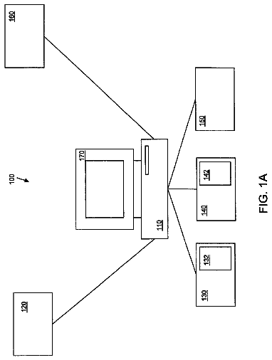
FIG. 1A is a representative diagram illustrating two computing devices that can be inductively linked to provide a power and/or data signal to the other device, according to an embodiment.
FIG. 1B illustrates a housing segment for a mobile computing device that is modularized to configure the computing device to establish an inductive link with another device, under an embodiment.
FIG. 2A is a simplified block diagram of two devices that are inductively linked, in accordance with one or more embodiments.
FIG. 2B illustrates an inductive signal path, as extended from or between two devices that are inductively linked, according to one or more embodiments.
FIG. 3A through FIG. 3C illustrate different coil distribution implementations for inductive signal conveyance, under different embodiments or variations.
FIG. 4 illustrates a simplified block diagram of a computing system that provides for inductive conveyance of power and/or data signals, under an embodiment.
FIG. 5 is a simplified block diagram of a computing device configured in accordance with an embodiment.
FIG. 6 is a simplified block diagram of a docking station, configured in accordance with an embodiment.
FIG. 7A is a simplified block diagram of a mobile computing device having components for implementing an inductive signal interface in combination with another device, according to an embodiment.
FIG. 7B is a circuit-level diagram illustrating exemplary circuit configurations of a portion of the system shown in FIG. 7A.
FIG. 8 illustrates details for a magnetic coil that can be used on a computing device, in accordance with one or more embodiments.
FIG. 9A is a simplified block diagram of a docking station (or other accessory device) having components for implementing an inductive signal transfer system in combination with another device, according to an embodiment.
FIG. 9B is a circuit-level diagram illustrating a suitable circuit configuration of output circuitry of a docking station, as described by FIG. 9A, under an embodiment.
FIG. 9C is a circuit-level diagram depicting a suitable circuit configuration for an inductive receiver on a docking, under an embodiment.
FIG. 9D and FIG. 9E illustrate a coil assembly or sub-assembly for use on one or both devices, under another embodiment.
FIG. 9F illustrates an alternative embodiment for inductively coupling a dock and mobile computing device, under another embodiment.
FIG. 10 illustrates a process or method implemented on two computing devices to enable an efficient and safe inductive signaling environment, under embodiment.
FIG. 11 illustrates steps performed on respective power supply and power receiving devices in enabling two such devices inductively link to one another under a controlled protocol or process, according to an embodiment.
FIG. 12 is a state diagram of the operation status of a power supply device, under an embodiment.
FIG. 13 illustrates communication packets that can be exchanged between devices, according to embodiments described herein.
FIG. 14 illustrates various inductive signal modulations, as interpreted in binary form, under an embodiment.
FIG. 15 illustrates a method in which an orientation of a mobile computing device is selectable to affect operations or functionality resulting from one or both docked devices, under an embodiment.
FIG. 16A illustrates an implementation of structural surface features that may be provided with the mobile computing device and/or the dork, under an embodiment.
FIG. 16B illustrates an implementation in which structure surface features may be used to mechanically retain a mobile computing device on a platform of a dock, under an embodiment.
FIG. 16C illustrates an implementation in which a set of insertive clasps may be used to mechanically retain a mobile computing device on a platform of a dock, under an embodiment.
FIG. 17 illustrates a configuration for a back face of a mobile computing device, under an embodiment.
FIG. 18 illustrates a top view of a receiving surface for a dock that includes an arrangement of magnets, under an embodiment.
FIG. 19 illustrates a side cross-sectional view of a dock with an arrangement of magnets, under another embodiment.
FIG. 20 illustrates a mobile computing device docked onto a dock using magnetic clasping, under an embodiment.
FIG. 21 illustrates a perspective view of a ring interface for a magnetic clasp, under an embodiment.
FIG. 22 illustrates an implementation with four magnets positioned equidistant to one another, under an embodiment.
FIG. 23 illustrates an embodiment of a magnetic element which may be used for magnetic clasping, under an embodiment.
FIG. 24 illustrates a cross-sectional view of a dock and a mobile computing device under an embodiment.
FIG. 25 illustrates an embodiment in which the mobile computing device may couple to a sticky-back accessory device.
FIG. 26 illustrates an embodiment for enabling a dock to establish an inductive link with a mobile computing device in order to subsequently communicate data for extending a functionality or resource to the mobile computing device.
FIG. 27 illustrates variations on how to enable a mobile computing device to leverage functionality and/or connectivity provided from a dock, under an embodiment.
FIG. 28 illustrates variations of a touch-and-go embodiment for a pair of computing devices, under an embodiment.
FIG. 29 illustrates a mobile computing device with an audio dock, under an embodiment.
FIG. 30 illustrates a mobile computing device placed in a landscape orientation on an audio dock, under an embodiment.
FIG. 31 illustrates a mobile computing device placed in a portrait orientation on an audio dock, under another embodiment.
FIG. 32 illustrates a variation to an audio dock, under an embodiment.
FIG. 33 illustrates another variation in which an audio dock is comprised of an interface to a vehicle's audio output components, under an embodiment.
FIG. 34A illustrates an implementation in which a dock is associated or connected with another device, under an embodiment.
FIG. 34B illustrates an implementation in which a projector dock is associated or connected with another device, under another embodiment.
FIG. 34C illustrates an embodiment in which a printer dock is associated or connected with another device, under an embodiment.
FIG. 35A illustrates an embodiment for enhancing the functionality of a mobile computing device by inductively linking the mobile computing device with another device.
FIG. 35B illustrates another embodiment for enhancing the functionality of a mobile computing device by inductively linking the mobile computing device with another device for a brief moment.
FIG. 35C illustrates another embodiment for enhancing the functionality of a mobile computing device through wireless access.
FIG. 36 illustrates a process for configuring a mobile computing device based on a specific docking station that the mobile computing device is docked to, under an embodiment.
FIG. 37 illustrates a mobile computing device that can inductively link with more than one dock, under an embodiment.
Detailed description
Embodiments described herein enable a device to be inductively linked with another device in order to exchange or leverage functionality amongst the two devices. Some embodiments provide for an inductive link to be established amongst two computing devices. The inductive link is used to signal power and/or data. As described by numerous embodiments, the inductive link may be used to configure functionality or operations on one or all of the inductively linked devices.
Embodiments described herein provide for a computing system or devices that comprise part of the computing system In an embodiment, a docking station is provided for a computing device. The docking station may be used by, for example, a mobile computing device, such as a cellular or wireless telephony/messaging device. The docking station includes a housing comprising a receiving surface top receive and retain the mobile computing device. An inductive signal transfer interface is included with the housing to inductively signal at least one of power or data to the mobile computing device. The docking station further provides an output component and processing resources. The processing resources are configured to detect placement of the mobile computing device on the receiving surface. The data is received from the mobile computing device, and an output is signaled to the output component based on the received data.
According to some embodiments, the docking station is an audio dock-so as to include speakers as output devices. Other examples of docking stations are recited herein.
Still further, embodiments described herein include a computer system that includes a first computing device and a second computing device that are inductively linked to one another. One of the two devices inductively signals an identifier to the other device. Upon receiving the identifier, the other device configures one or more operations. The operations are selected or otherwise configured based on the signaled identifier.
According to one embodiment, a mobile computing device (`MCD`) and docking station (`dock`) are individually equipped with features and components that enable charging/power signals to be communicated from the dock to the MCD without use of connectors. As an addition or an alternative, the dock and/or MCD may exchange or transmit data signals to the other device when the MCD is retained against the dock (i.e. `docked`).
Some embodiments described herein may be implemented using programmatic elements, often referred to as modules or components, although other names may be used. Such programmatic elements may include a program, a subroutine, a portion of a program, or a software component or a hardware component capable of performing one or more stated tasks or functions. As used herein, a module or component, can exist on a hardware component independently of other modules/components or a module/component can be a shared element or process of other modules/components, programs or machines. A module or component may reside on one machine, such as on a client or on a server, or a module/component may be distributed amongst multiple machines, such as on multiple clients or server machines. Any system described may be implemented in whole or in part on a server, or as part of a network service. Alternatively, a system such as described herein may be implemented on a local computer or terminal, in whole or in part. In either case, implementation of system provided for in this application may require use of memory, processors and network resources (including data ports, and signal lines (optical, electrical etc.), unless stated otherwise.
Some embodiments described herein may generally require the use of computers, including processing and memory resources. For example, systems described herein may be implemented on a server or network service. Such servers may connect and be used by users over networks such as the Internet, or by a combination of networks, such as cellular networks and the Internet. Alternatively, one or more embodiments described herein may be implemented locally, in whole or in part, on computing machines such as desktops, cellular phones, personal digital assistances or laptop computers. Thus, memory, processing and network resources may all be used in connection with the establishment, use or performance of any embodiment described herein (including with the performance of any method or with the implementation of any system).
Furthermore, some embodiments described herein may be implemented through the use of instructions that are executable by one or more processors. These instructions may be carried on a computer-readable medium. Machines shown in figures below provide examples of processing resources and computer-readable mediums on which instructions for implementing embodiments of the invention can be carried and/or executed. In particular, the numerous machines shown with embodiments of the invention include processor(s) and various forms of memory for holding data and instructions. Examples of computer-readable mediums include permanent memory storage devices, such as hard drives on personal computers or servers. Other examples of computer storage mediums include portable storage units, such as CD or DVD units, flash memory (such as carried on many cell phones and personal digital assistants (PDAs), and magnetic memory. Computers, terminals, network enabled devices (e.g. mobile devices such as cell phones) are all examples of machines and devices that utilize processors, memory, and instructions stored on computer-readable mediums.
Overview
FIG. 1A is a representative diagram illustrating two computing devices that can be brought into contact for purpose of enabling one device to provide a power and/or data signal to the other device, according to an embodiment. Numerous embodiments described herein, including an embodiment such as described with FIG. 1, reference a MCD and dock as two devices that are brought into contact with one another for purpose of power/data transfer without use of traditional insertive or mechanically coupled connectors. However, different kinds of devices (e.g. portable devices and accessory devices) may be used with embodiments described herein. In many of the examples provided herein, two devices that are inductively coupled correspond to a mobile computing device (also referred to as an MCD) and an accessory device (specifically a dock or docking station). However, embodiments may also be implemented using other types of devices. In one implementation, the MCD is a mufti-purpose device having cellular data and telephonic capabilities, while the accessory device corresponds to, for example, a docking station (for communications and power supply), sticky (or piggy)-back accessory, a light projector, a speaker set, or headset station. As an addition or alternative to cellular telephony/data capabilities, the MCD may include, for example, functionality for use as a media player, a camera or video recorder, a global positioning unit, an ultramobile personal computer, a laptop computer, or a mufti-purpose computing device. Numerous other examples and implementations are described herein, including embodiments in which three or more devices are interconnected through one or more connector-less connections.
Accordingly, a system 100 includes a MCD 110 that is supported or otherwise retained by a dock 120. The manner in which the MCD 110 is supported may vary. Moreover, as described with one or more embodiments, the orientation of the MCD on the dock may be changed by the user for purpose of configuring operations or behavior of one or both devices. According to an orientation of an embodiment shown, the MCD 110 is supported on the dock 120 in a partially upright position along its length axis (L). Such an orientation may correspond to a `portrait` position. In an embodiment in which alternative orientations are possible, one or more `landscape` positions, or positions in between the portrait and landscape positions may be possible.
According to an embodiment, the dock 120 utilizes physical support structures (not shown), such as shelves, platforms, hooks or mechanical retention features, to retain the MCD 110 in a docked or mated position. In another embodiment, magnetic clasps may be included or provided the dock 120 and/or the MCD 110 to secure retention of the MCD against the dock. Priority U.S. patent application Ser. No. 12/239,656, which is incorporated by reference herein in its entirety, details the use of magnetic clasps and ferrous (or other) material in order to physically retain the MCD 110 in a docked position with the dock 120.
The dock 120 may include resources 121 for generating or extending power and/or data signals to the MCD 110. For example, the dock 120 may be mated with a power outlet 124 or another computer 126 (e.g. desktop computer) to extend power and/or data signals. The resources 121 may include circuitry or hardware, such as AC/DC converters and regulators. In order to enable the dock 120 to receive electrical power from a personal computer or other computing station, one implementation provides for the dock 120 to include a physical connector port, such as provided by a Universal Serial Bus (USB) connector. Additionally, the dock 120 may include data acquisition capabilities, provided through connector ports with the computer 126, wireless ports (e.g. cellular, WiMax connection, Bluetooth), Internet ports, and media feeds (e.g. provided through television tuner and cable).
As shown by an embodiment of FIG. 1, the MCD 110 has a housing shell 112 having a thickness (t). The housing shell 112 may be used to retain internal components of the MCD 110, such as a circuit board, processor, memory, or components of a display assembly. The MCD 110 may be structured so that a primary facade 115 (e.g. the back panel) of the housing shell 112 rests on a receiving surface 125 of the dock 120.
Embodiments described herein provide a system and technique for delivering electrical power over short distances without the use of electrical conductors In one embodiment, the MCD 110 and dock 120 are inductively coupled. The MCD 110 may be placed physically on the dock 120 to inductively couple one or both of a power and data signal. In other embodiments, the MCD 110 and dock 120 may be placed near one another without physical contact.
As an alternative or addition, the MCD may be equipped with orientation sensors such as accelerometers in order for the device to detect its own orientation with reference to gravity. The MCD 110 may include functionality that enables or automatically performs based on its orientation on the dock 120 (e.g. landscape or portrait). In one embodiment, the device communicates its orientation to the dock (e.g. inductively or through wireless (RF) communication medium) so that the dock 120 can facilitate or perform functions that are consistent with the operations the MCD performs in a given orientation. In order to enable the accelerometer (or other sensor) of the MCD to detect its own position, the angle of support provided by the dock 120 may be such that the sensor is operable. For example, some embodiments described herein employ accelerometers, in which case the angle with the horizontal in which the MCD 110 is supported in place is at least 22.5 degrees.
Alternative Housing Implementation and Configuration
While many examples described elsewhere specifically recite implementations in which inductive charging occurs between two devices that are a mobile computing device and dock (or docking station), the recited embodiments may be equally applied between devices that are more generically recited as being either a power supply or power receiving device. Some embodiments recognize that inductive charging can be performed by or with other types of computing devices. For example, rather than use a docking station which supports the mobile computing device in some operable decision, the accessory device can have an alternative form factor that enables it to be carried on the device.
Likewise, the mobile computing device can carry inductive charging capabilities as an accessory feature. FIG. 1B, for example, illustrates a housing segment 180 that can be overlaid onto, or assembled in place of an existing housing segment 190 on the mobile computing device 110. The housing segment 180 includes signal handler resources 182 (as described with embodiments of FIG. 7A and elsewhere in this application) for enabling inductive signal transfer with another device. The housing segment 180 may be purchased separately from the MCD 110, and assembled onto the MCD by the user to enable the MCD to have capabilities of inductive charging (power receive), inductive power signaling, and/or inductive data transfer. In one embodiment, the housing segment 180 is a battery cover for the MCD. A data and power bus 184 may interconnect the inductive signaling resources 182 of the housing segment with a battery and other electronic components of the computing device.
In an embodiment in which the MCD 110 is coupled to the dock using magnetic clasps, the exterior surface of the housing segment 180 may include some or all of the ferrous material (or magnets) that device 110 needs to magnetically couple with the dock or accessory. As an alternative, the ferrous material may be provided on other portions of the housing of the MCD, other than the segment 180. For purpose of applications described herein, reference to a mobile computing device with inductive signal receiving/transmitting capabilities may include a device that has its housing accessorized or replaced in part post-manufacturing or sale.
Inductive Signal Path
FIG. 2A is a simplified block diagram of a MCD 210 and dock 220, where one or both devices are configured to communicate signals on a signal path that has an inductive signal path portion, so as to form a partially inductive signal path. According to an embodiment, the MCD 210 may be placed in contact with the dock 220, such as in a manner described with other embodiments (such as described with FIG. 1). The result is that a device exterior 208 (e.g. rear facade) comes into contact with a receiving surface 228 of the dock. Alternatively, the two devices may be brought into close proximity, but not necessarily in contact, in order for inductive signal communication to take place. While exterior surfaces 208, 228 of MCD 210 and dock 220 respectively may be in contact as a result of the retention of the MCD by the dock, the contact is not made to conductively transfer signals between the devices. Rather, a signal source 224 on the dock 220 (e.g. such as a power inlet) may generate a signal 228 (e.g. power) that is transformed through a magnetic coil 226 or other inductive mechanism into a magnetic field. A corresponding coil 214 or inductive receiving component may be provided on the MCD 210 to transform the signal 228 into an electrical signal 216. The electrical signal 216 may be treated by various circuit elements and components in order to power components of the MCD 210, and/or to charge a battery module 219 of the device 210.
FIG. 2B illustrates an inductive signal path 250, as extended from or between the dock 220 to the MCD 210, using a combination of magnetic/inductive and conductive elements provided on both devices. On the dock, the signal path 250 includes a current phase 252 and an inductive (or magnetic field) phase 254. The inductive phase 254 carries the signal across boundaries of respective housings using magnetic field. Thus, on the device 210, the signal path 250 includes an inductive phase 254, followed by a current phase 256. The reverse path may also be possible, such as in the case when the MCD supplies power and/or data to the docking station or another accessory device.
Inductive Coil Arrangements
The inductive conveyance of power and/or data signals may be achieved through use of coils, provided on each device that is to be coupled to transmit or receive such signals. Various coil configurations are possible to enable conveyance of power and/or data, either unidirectionally or bi-directionally.
FIG. 3A through FIG. 3C illustrate different coil distribution implementations for inductive signal conveyance, under different embodiments or variations. In particular, FIG. 3A illustrates a system or sub-system that includes two coils, one on each device. The two coils 302, 304 may be used to convey power and/or data in one signal 301 that is exchanged between the two devices. Moreover, the conveyance of either power or data may be bi-directional.
FIG. 3B illustrates a three-coil implementation, where one of the two devices (e.g. the dock 220) includes two coils 312, 314, and the other device (e.g. MCD 210) includes just one coil 316. Such an embodiment may provide the advantage of lessening the weight or size required from the MCD, while enabling separate data and power exchange. In one embodiment, the coil 316 of the MCD 210 receives power 311 from one coil 312 on the dock, and data 313 from the other coil 314. Optionally, either the power 311 or the data 313 signals may be bi-directional, meaning the coil 316 on the MCD 210 may communicate the signals back to the dock 220. In one implementation, the coil on the MCD 210 signals data to the independent data coil on the dock 220.
FIG. 3C illustrates another implementation in which each of the dock 320 and MCD 310 include two coils. In particular, power and data coils 322, 324 on the dock 320 may communicate power 321 and data 323 signals to respective coils 332, 334 on the MCD 310. In an embodiment, the power and data communications are bi-directional.
Computer System Using Inductive Signal Path
FIG. 4 illustrates a simplified block diagram of a computing system that provides for inductive conveyance of power and/or data signals, under an embodiment. The computing system 400 includes MCD 410 and dock 420 that are structured to enable inductive signal transfer exchange, in accordance with numerous embodiments described herein. In an embodiment, the dock 420 includes a central processor 424, a power subsystem 422 and a communication subsystem 426. The MCD 410 includes a power subsystem 412, a signal processor 414, and a communication subsystem 416. Additionally, the MCD 410 (and optionally the dock 420) includes numerous other components, such as a central processor and memory resources for enabling application executions, cellular and data communications, and numerous other functions that are part of the usage of the MCD 410.
On the dock 420, the power subsystem 422 includes a connection to a continuous power supply 421, such as a wall outlet. Additionally, the power subsystem 422 includes components for converting and regulating the signals from the power supply into a form that is suitable for conveyance using, for example, an inductive medium. Additionally, the power subsystem 422 includes one or more coils for converting an electrical signal originating from the power supply 421 into an inductive signal. The communication subsystem 426 may include wireless or wireline port(s) to receive and send data to other devices, including with other computers or data sources (e.g. media feeds from other devices, such as set-top boxes) or media output devices. In an embodiment, the communication subsystem 426 also enables inductive data handling from data communicated by one of the inductive signal paths that extend between the two devices. As mentioned, such data may be conveyed by either modulating an inductive power signal or using a separate data signal path.
The central processor 424 of the dock 420 may be configured to handle incoming data signals from the communication subsystem 426, whether from the other resource or from the MCD 410. Additionally, the central processor 424 may control data that is communicated out, either to the other resource or to the MCD 410 (using the inductive signal path).
On the MCD 410, an embodiment provides that the power subsystem 412 receives an incoming power signal 408 from the dock 420 and distributes the power signal in modified or regulated form to either other components or to the battery for recharge. The power signal 408 is signaled through an inductive path from the dock 420 to the MCD 410, in a unidirectional fashion. The communication subsystem 416 is configured to communicate with the dock 420 to receive and/or transmit data 409. One embodiment provides that the communication subsystem 416 may include resources to demodulate data carried on the power signal. In particular, the communication subsystem 416 may use its resources to implement one or more protocols, such as (i) a protocol for regulating the inductive delivery of power with exchange of data that communicates current/voltage information (e.g. use levels) on the receiving device, (ii) a credential protocol for retrieving and using credential information (e.g. preliminary data for establishing subsequent wireless communications) from characteristics of modulations in the power signal 408. One or both protocols may further provide for the communication subsystem 416 to switch to, for example, a standardized wireless communication medium (e.g. BLUETOOTH) using the credential information and/or other data communicated by the power signal 408. Still further, another embodiment may provide for the communication subsystem 416 to be enabled to generate modulated power or other signals to communicate to the dock 420 or other device. For example, as shown by FIG. 3B, two coils may be used on the dock, including one coil that communicates both power and data and another that receives data from the MCD 410. The communication subsystem 416 may perform functions of both retrieving data from the modulated data signal and communicating data out to the data receiving coil on the MCD 410.
As described with some other embodiments, data is also combined with the power signal 408 by modulating the power signal. In one implementation, the dock 420 signals data 409 with the power signal 408 as a preliminary step to establishing a different wireless communication relationship. In another embodiment, the data signal 409 may be communicated to or from the MCD separate from the power signal.
Device Block Diagrams
FIG. 5 is a simplified block diagram of a MCD, according to an embodiment. A MCD 500 may be configured to include any of the functionalities or capabilities described with other embodiments, including the ability to receive electrical signals (power and/or data) using conductive or inductive signal paths. Thus, as mentioned with other embodiments, the MCD 500 may correspond to, for example, a `smart phone`, a mobile companion, a media player, a digital camera, or a GPS unit (or to a mufti-function device that can perform as many of the devices described).
More specifically, one or more embodiments provide that the MCD 500 may correspond to a mobile telephony/data messaging computing device, such as a cellular phone or mobile device with voice-telephony capabilities (sometimes called "smart phone"). A computing device such as described may be small enough to fit in one hand, while providing cellular telephony features in combination with other applications, such as messaging, web browsing, media playback, personal information management (e.g. such as contact records management, calendar applications, tasks lists), image or video/media capture and other functionality. Other examples of functionality that may be provided from the MCD 500 include audio and/or video playback or Global Positioning Services (GPS) as primary or enabled functions. The MCD 500 may have numerous types of input mechanisms and user-interface features, such as keyboards or keypads, mufti-directional or navigation buttons, application or action buttons, and contact or touch-sensitive display screens or buttons. In the case of data messaging/communication devices, specific types of messaging or communications that may be performed includes messaging for email applications, Short Message Service (SMS), Multimedia Message Service (MMS), and proprietary voice exchange applications (such as SKYPE). Still further, the MCD 500 may correspond to numerous other types of computing devices, such as to a notebook computer, an ultra-mobile computer, or a personal digital assistant.
According to an embodiment, the MCD 500 includes one or more processors 510, memory resources 520, a display assembly 528, one or more communication ports 530, and a power module 540. In an embodiment, the MCD 500 includes a signal handler resource 550 (or module), which includes hardware and logic for accepting and/or transmitting power or data signals using an inductive communication medium. As another option, the MCD 500 includes one or more detectors 560 (or sensors) for detecting orientation or position of the MCD 500 when the device is docked to the accessory device.
The processor 510 may include or communicate with the signal handling resource 550 to enable some or all of the signal handling capabilities for enabling inductive receipt or transmission of signals. The communication ports 530 may include wireless or wireline ports. Wireless communication ports may be implemented through, for example, local wireless communication protocols such as provided by BLUETOOTH standards, Wireless Fidelity (802.11(b) or (g)). The wireless communication ports may also communicate over a cellular network. More specifically, the MCD 500 may include one or more wireless communication ports to provide wireless connectivity of a particular type (or types) for purpose of carrying out any one or more types of wireless operations. For example, the communication port 530 may include or correspond to (i) a Wide Area Network (WAN) radio module for sending and receiving cellular voice/data, (ii) a local wireless communication port such as Bluetooth or wireless USB, (iii) an infrared port, (iv) a Global Positioning System radio, and/or (v) a WiMAX radio.
The memory resources 520 may, for example, include Flash memory, Random Access Memory, and/or persistent memory (i.e. ROM). The memory resources 520 include instructions and data for implementing functionality and programmatic actions such as provided with any of the embodiments described. Optionally, the memory resources 520 may carry databases or data stores of records that contain active data items (such as described above) for synchronization or communication with a primary computer, and/or enable actions on such data items of saving the data items.
According to an embodiment, the signal handler resource 550 includes hardware for receiving or transmitting a power signal and/or a data signal (either modulated or combined as one signal) to and/or from the dock. Additional details of components and elements for signal handler resource 550 to enable an inductive signal path is detailed with various embodiments described above. In one embodiment, the signal handler resource 550 is configured to receive a power signal for purpose of either powering other components (e.g. display assembly 528) of the MCD 500, or to recharge the battery of the power module 540. In one implementation, the incoming power signal may be treated using circuits and components that are separate from a central processor of the MCD 500. Thus, processor 510 may include more than one unit or resource. In one implementation, for example, the MCD 500 includes both a signal processor (which may be incorporated with the signal handler 550) and a central processing unit (CPU).
As described elsewhere, an embodiment provides that the MCD is configured to use the signal handler resource 550 to convey and/or receive some data that enables subsequent communications between the devices. This data may include credential data 552, which enable subsequent wireless communications using, for example, a local wireless communication link via one of the local wireless communication ports 530. The credential data 552 may be stored within a portion of the memory resources and made available to the processing resources for inclusion or use with functions performed by the signal handling resource 550. In one embodiment, the signal handling resource 550 is capable of inductively communicating at least some of the credential data through a modulated power signal. As an addition or variation, the signal handling resource 550 is capable of recognizing or using the credential data 552, inductively communicated from the dock, to identify and pair with the dock.
In one embodiment, the detectors 560 are provided in the form of sensors that independently detect the orientation of the MCD 500. For example, the detectors 560 may correspond to accelerometers or vertical position sensors that detect the orientation of the MCD 500 at any given instance. In another embodiment, the detectors 560 sense or communicate data or signals to electrical or conductive (or inductive) pads that are positioned on an exposed surface of the dock. Thus, the position of the MCD may be detected by determining which detectors 560 and/or sensors or conductive pads are in contact when the two devices are docked.
Information identifying the orientation of the MCD 500 when docked may affect various operations or modes/states of the MCD and/or its components. The detectors 560 may signal or communicate the orientation information 562 to the processor 510 of the MCD. In one implementation, for example, the processor 510 is configured to use the orientation information 562 to signal a display state 529 to the display assembly 528. The display assembly 528 may, for example, be switched between portrait and landscape mode in response to the signal.
FIG. 6 is a simplified block diagram of a dock, under an embodiment. The dock 600 may correspond to any of the docks described with other embodiments herein. In particular, a dock as described may be used to implement (depending on the embodiment) an inductive signal path for communicating power and data with a MCD such as described with FIG. 6. In an embodiment, the dock 600 includes processing resources 610, a signal handler 620, memory resources 630, and a power resource 640. The dock 600 may also include one or more communication ports, including a wireless communication port 642 and/or one or more wireline communication ports 644.
The processing resources 610 enables intelligent operations, such as authenticating or pairing with the MCD 500 (see FIG. 6) (e.g. over a wireless link) and/or data sharing/synchronization operations (with MCD 500). In one variation, the dock 600 is also capable of interfacing with a computing resource (e.g. other device or computer) to enable synchronization or data sharing operations between the MCD 500 and third device, or between the dock and the third device. In an embodiment, the processing resources 610 correspond to or include a signal processor which is able to receive or transmit data through modulations in the power signal.
The description continues in the full USPTO document.
 Lapsed, fee not paid12 drawings

