Technical field
The present technology relates to a transmission device, a transmission method, a reception device, and a reception method, and more particularly to, for example, a transmission device, a transmission method, a reception device, and a reception method for securing favorable communication quality in data transmission using an LDPC code.
Background art
Low density parity check (LDPC) codes have high error correction capability and are in recent years widely adopted in transmission systems for digital broadcasting and the like, such as the digital video broadcasting (DVB)-S.2 in Europe and the like, DVB-T.2, DVB-C.2, and the advanced television systems committee (ATSC) 3.0 in the United States, and the like, for example (see, for example, Non-Patent Document 1).
With recent researches, it has been found that the LDPC codes are able to obtain performance close to the Shannon limit as the code length is increased, similarly to turbo codes and the like. Furthermore, the LDPC codes have a property that the minimum distance is proportional to the code length and thus have a good block error probability characteristic, as characteristics. Moreover, a so-called error floor phenomenon observed in decoding characteristics of turbo codes and the like hardly occur, which is also an advantage. CITATION LIST Non-Patent Document
Non-Patent Document 1: ATSC Standard: Physical Layer Protocol (A/322), 7 Sep. 2016 SUMMARY OF THE INVENTION Problems to be Solved by the Invention
In data transmission using an LDPC code, for example, the LDPC code is symbols (symbolized) of quadrature modulation (digital modulation) such as quadrature phase shift keying (QPSK), and the symbols are mapped at signal points of the quadrature modulation and are sent.
The data transmission using an LDPC code is spreading worldwide and is required to secure favorable communication (transmission) quality.
The present technology has been made in view of such a situation, and aims to secure favorable communication quality in data transmission using an LDPC code. Solutions to Problems
A first transmission device/transmission method of the present technology is a transmission device/transmission method including: an encoding unit/step of performing LDPC coding on the basis of a parity check matrix of an LDPC code with a code length N of 17280 bits and a coding rate r of 9/16, in which the LDPC code includes information bits and parity bits, the parity check matrix includes an information matrix portion corresponding to the information bits and a parity matrix portion corresponding to the parity bits, the information matrix portion is represented by a parity check matrix initial value table, and the parity check matrix initial value table is a table representing positions of elements of 1 of the information matrix portion for every 360 columns, and is
TABLE-US-00001 291 817 1023 1118 1168 1195 1419 1763 2507 3005 3886 3952 4046 4924 5372 5586 5742 5925 6080 6157 6301 6600 6644 7052 7093 7105 7487 133 565 957 1018 1150 1196 1210 1224 1361 1484 2330 2448 2525 2583 2639 3198 3407 3504 4272 4383 5133 5399 5421 5545 6972 7156 129 365 541 1026 1199 1527 2467 3386 3458 4215 4438 4778 5176 5484 5521 5540 5788 6103 6287 6360 6605 6745 6973 7251 7329 7336 996 1392 2493 2910 3048 3281 4969 5189 5632 6236 6983 165 2521 2650 2824 3493 4637 5670 6470 266 345 390 2365 2843 3274 4321 5165 245 2173 2274 2687 3763 4284 5562 6564 2787 2970 3503 691 3718 5047 593 969 3593 331 3809 6269 1627 2886 5935 1046 2976 4457 4725 6028 6458 6172 6610 7530 1536 7102 7148 233 2463 4955 826 4319 6969 3073 6675 6774 407 4251 7087 1380 3802 4937 1911 4360 6306 4027 6219 7292 398 1190 1936 250 830 7241 5500 5828 7478 1261 4649 7237.
In the first transmission device and transmission method of the present technology, LDPC coding is performed on the basis of a parity check matrix of an LDPC code having a code length N of 17280 bits and a coding rate r of 9/16. The LDPC code includes the information bits and parity bits, the parity check matrix includes the information matrix portion corresponding to the information bits and the parity matrix portion corresponding to the parity bits, the information matrix portion is represented by the parity check matrix initial value table, and the parity check matrix initial value table is a table representing positions of elements of 1 of the information matrix portion for every 360 columns, and is
TABLE-US-00002 291 817 1023 1118 1168 1195 1419 1763 2507 3005 3886 3952 4046 4924 5372 5586 5742 5925 6080 6157 6301 6600 6644 7052 7093 7105 7487 133 565 957 1018 1150 1196 1210 1224 1361 1484 2330 2448 2525 2583 2639 3198 3407 3504 4272 4383 5133 5399 5421 5545 6972 7156 129 365 541 1026 1199 1527 2467 3386 3458 4215 4438 4778 5176 5484 5521 5540 5788 6103 6287 6360 6605 6745 6973 7251 7329 7336 996 1392 2493 2910 3048 3281 4969 5189 5632 6236 6983 165 2521 2650 2824 3493 4637 5670 6470 266 345 390 2365 2843 3274 4321 5165 245 2173 2274 2687 3763 4284 5562 6564 2787 2970 3503 691 3718 5047 593 969 3593 331 3809 6269 1627 2886 5935 1046 2976 4457 4725 6028 6458 6172 6610 7530 1536 7102 7148 233 2463 4955 826 4319 6969 3073 6675 6774 407 4251 7087 1380 3802 4937 1911 4360 6306 4027 6219 7292 398 1190 1936 250 830 7241 5500 5828 7478 1261 4649 7237.
A first reception device/reception method of the present technology is a reception device/reception method including: a decoding unit/step of decoding an LDPC code with a code length N of 17280 bits and a coding rate r of 9/16, the LDPC code being obtained from data transmitted by a transmission method including an encoding step of performing LDPC coding on the basis of a parity check matrix of the LDPC code, in which the LDPC code includes information bits and parity bits, the parity check matrix includes an information matrix portion corresponding to the information bits and a parity matrix portion corresponding to the parity bits, the information matrix portion is represented by a parity check matrix initial value table, and the parity check matrix initial value table is a table representing positions of elements of 1 of the information matrix portion for every 360 columns, and is
TABLE-US-00003 291 817 1023 1118 1168 1195 1419 1763 2507 3005 3886 3952 4046 4924 5372 5586 5742 5925 6080 6157 6301 6600 6644 7052 7093 7105 7487 133 565 957 1018 1150 1196 1210 1224 1361 1484 2330 2448 2525 2583 2639 3198 3407 3504 4272 4383 5133 5399 5421 5545 6972 7156 129 365 541 1026 1199 1527 2467 3386 3458 4215 4438 4778 5176 5484 5521 5540 5788 6103 6287 6360 6605 6745 6973 7251 7329 7336 996 1392 2493 2910 3048 3281 4969 5189 5632 6236 6983 165 2521 2650 2824 3493 4637 5670 6470 266 345 390 2365 2843 3274 4321 5165 245 2173 2274 2687 3763 4284 5562 6564 2787 2970 3503 691 3718 5047 593 969 3593 331 3809 6269 1627 2886 5935 1046 2976 4457 4725 6028 6458 6172 6610 7530 1536 7102 7148 233 2463 4955 826 4319 6969 3073 6675 6774 407 4251 7087 1380 3802 4937 1911 4360 6306 4027 6219 7292 398 1190 1936 250 830 7241 5500 5828 7478 1261 4649 7237.
In the first reception device and the first reception method of the present technology, the LDPC code obtained from the data transmitted by the first transmission method is decoded.
A second transmission device/transmission method of the present technology is a transmission device/transmission method including: an encoding unit/step of performing LDPC coding on the basis of a parity check matrix of an LDPC code with a code length N of 17280 bits and a coding rate r of 10/16, in which the LDPC code includes information bits and parity bits, the parity check matrix includes an information matrix portion corresponding to the information bits and a parity matrix portion corresponding to the parity bits, the information matrix portion is represented by a parity check matrix initial value table, and the parity check matrix initial value table is a table representing positions of elements of 1 of the information matrix portion for every 360 columns, and is
TABLE-US-00004 579 608 613 760 795 839 910 1895 2239 2535 2670 2871 3127 3316 3779 3829 3936 4454 4772 4926 6048 6166 6352 263 291 694 1172 1232 1925 2657 3037 3057 3400 3550 3812 4185 4325 5202 5441 5479 5640 5864 5892 6154 6157 6227 527 601 1254 1476 1760 2070 2099 2725 2961 3529 3591 4324 4393 4462 4841 5070 5480 5698 5856 5865 6087 6446 235 319 480 2036 2188 2358 2423 2510 2911 3225 3472 3677 3840 4409 4574 4892 5119 5548 5805 5901 6290 6477 1809 2974 3464 5295 5490 5671 2148 3629 4304 4854 4876 6037 2031 2246 3358 4679 6125 6331 874 2483 2964 3872 4509 4904 4001 4303 5079 1652 4524 5263 2551 3381 5524 713 1908 6304 2722 3347 6201 433 923 5564 2181 4242 6202 51 2711 4435 414 708 5539 2222 5036 5974 784 3588 5125 4256 5004 5540 1761 2781 6037 1547 2266 4377 4109 5836 6337 767 2468 4764 2528 5457 5872 884 4651 4807 161 3582 5164 744 2624 4852 239 1740 5807 33 3595 5121.
In the second transmission device and the second transmission method of the present technology, the LDPC coding is performed on the basis of the parity check matrix of the LDPC code with the code length N of 17280 bits and the coding rate r of 10/16. The LDPC code includes the information bits and parity bits, the parity check matrix includes the information matrix portion corresponding to the information bits and the parity matrix portion corresponding to the parity bits, the information matrix portion is represented by the parity check matrix initial value table, and the parity check matrix initial value table is a table representing positions of elements of 1 of the information matrix portion for every 360 columns, and is
TABLE-US-00005 579 608 613 760 795 839 910 1895 2239 2535 2670 2871 3127 3316 3779 3829 3936 4454 4772 4926 6048 6166 6352 263 291 694 1172 1232 1925 2657 3037 3057 3400 3550 3812 4185 4325 5202 5441 5479 5640 5864 5892 6154 6157 6227 527 601 1254 1476 1760 2070 2099 2725 2961 3529 3591 4324 4393 4462 4841 5070 5480 5698 5856 5865 6087 6446 235 319 480 2036 2188 2358 2423 2510 2911 3225 3472 3677 3840 4409 4574 4892 5119 5548 5805 5901 6290 6477 1809 2974 3464 5295 5490 5671 2148 3629 4304 4854 4876 6037 2031 2246 3358 4679 6125 6331 874 2483 2964 3872 4509 4904 4001 4303 5079 1652 4524 5263 2551 3381 5524 713 1908 6304 2722 3347 6201 433 923 5564 2181 4242 6202 51 2711 4435 414 708 5539 2222 5036 5974 784 3588 5125 4256 5004 5540 1761 2781 6037 1547 2266 4377 4109 5836 6337 767 2468 4764 2528 5457 5872 884 4651 4807 161 3582 5164 744 2624 4852 239 1740 5807 33 3595 5121.
A second reception device/reception method of the present technology is a reception device/reception method including: a decoding unit/step of decoding an LDPC code with a code length N of 17280 bits and a coding rate r of 10/16, the LDPC code being obtained from data transmitted by a transmission method including an encoding step of performing LDPC coding on the basis of a parity check matrix of the LDPC code, in which the LDPC code includes information bits and parity bits, the parity check matrix includes an information matrix portion corresponding to the information bits and a parity matrix portion corresponding to the parity bits, the information matrix portion is represented by a parity check matrix initial value table, and the parity check matrix initial value table is a table representing positions of elements of 1 of the information matrix portion for every 360 columns, and is
TABLE-US-00006 579 608 613 760 795 839 910 1895 2239 2535 2670 2871 3127 3316 3779 3829 3936 4454 4772 4926 6048 6166 6352 263 291 694 1172 1232 1925 2657 3037 3057 3400 3550 3812 4185 4325 5202 5441 5479 5640 5864 5892 6154 6157 6227 527 601 1254 1476 1760 2070 2099 2725 2961 3529 3591 4324 4393 4462 4841 5070 5480 5698 5856 5865 6087 6446 235 319 480 2036 2188 2358 2423 2510 2911 3225 3472 3677 3840 4409 4574 4892 5119 5548 5805 5901 6290 6477 1809 2974 3464 5295 5490 5671 2148 3629 4304 4854 4876 6037 2031 2246 3358 4679 6125 6331 874 2483 2964 3872 4509 4904 4001 4303 5079 1652 4524 5263 2551 3381 5524 713 1908 6304 2722 3347 6201 433 923 5564 2181 4242 6202 51 2711 4435 414 708 5539 2222 5036 5974 784 3588 5125 4256 5004 5540 1761 2781 6037 1547 2266 4377 4109 5836 6337 767 2468 4764 2528 5457 5872 884 4651 4807 161 3582 5164 744 2624 4852 239 1740 5807 33 3595 5121.
In the second reception device and the second reception method of the present technology, the LDPC code obtained from the data transmitted by the second transmission method is decoded.
Note that the transmission device and the reception device may be independent devices or may be internal blocks configuring one device. Effects of the Invention
According to the present technology, good communication quality can be secured in data transmission using an LDPC code.
Note that effects described here are not necessarily limited, and any of effects described in the present disclosure may be exhibited.
Brief description of drawings
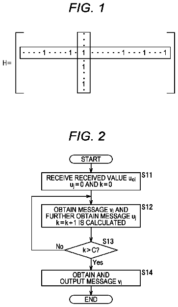
FIG. 1 is a diagram for describing a parity check matrix H of an LDPC code.
FIG. 2 is a flowchart for describing a procedure of decoding an LDPC code.
FIG. 3 is a diagram illustrating an example of a parity check matrix of an LDPC code.
FIG. 4 is a diagram illustrating an example of a Tanner graph of the parity check matrix.
FIG. 5 is a diagram illustrating an example of a variable node.
FIG. 6 is a diagram illustrating an example of a check node.
FIG. 7 is a diagram illustrating a configuration example of an embodiment of a transmission system to which the present technology is applied.
FIG. 8 is a block diagram illustrating a configuration example of a transmission device 11 .
FIG. 9 is a block diagram illustrating a configuration example of a bit interleaver 116 .
FIG. 10 is a diagram illustrating an example of a parity check matrix.
FIG. 11 is a diagram illustrating an example of a parity matrix.
FIG. 12 is a diagram for describing a parity check matrix of an LDPC code defined in the standard of DVB-T.2.
FIG. 13 is a diagram for describing a parity check matrix of an LDPC code defined in the standard of DVB-T.2.
FIG. 14 is a diagram illustrating an example of a Tanner graph regarding decoding of an LDPC code.
FIG. 15 is a diagram illustrating examples of a parity matrix H.sub.T having a step structure and a Tanner graph corresponding to the parity matrix H.sub.T.
FIG. 16 is a diagram illustrating the parity matrix H.sub.T of the parity check matrix H corresponding to the LDPC code after parity interleaving.
FIG. 17 is a flowchart for describing an example of processing performed by a bit interleaver 116 and a mapper 117 .
FIG. 18 is a block diagram illustrating a configuration example of an LDPC encoder 115 .
FIG. 19 is a flowchart for describing an example of processing of the LDPC encoder 115 .
FIG. 20 is a diagram illustrating an example of a parity check matrix initial value table with a coding rate of 1/4 and a code length of 16200.
FIG. 21 is a diagram for describing a method of obtaining the parity check matrix H from the parity check matrix initial value table.
FIG. 22 is a diagram illustrating a structure of a parity check matrix.
FIG. 23 is a diagram illustrating an example of a parity check matrix initial value table.
FIG. 24 is a diagram illustrating an A matrix generated from the parity check matrix initial value table.
FIG. 25 is a diagram for describing parity interleaving of a B matrix.
FIG. 26 is a diagram for describing a C matrix generated from the parity check matrix initial value table.
FIG. 27 is a diagram for describing parity interleaving of a D matrix.
FIG. 28 is a diagram illustrating a parity check matrix in which column permutation as parity deinterleaving for restoring parity interleaving is performed.
FIG. 29 is a diagram illustrating a transformed parity check matrix obtained by performing row permutation for the parity check matrix.
FIG. 30 is a diagram illustrating an example of a parity check matrix initial value table of a type A code with N=17280 bits and r=2/16.
FIG. 31 is a diagram illustrating an example of a parity check matrix initial value table of a type A code with N=17280 bits and r=3/16.
FIG. 32 is a diagram illustrating an example of a parity check matrix initial value table of a type A code with N=17280 bits and r=4/16.
FIG. 33 is a diagram illustrating an example of a parity check matrix initial value table of a type A code with N=17280 bits and r=5/16.
FIG. 34 is a diagram illustrating an example of a parity check matrix initial value table of a type A code with N=17280 bits and r=6/16.
FIG. 35 is a diagram illustrating an example of a parity check matrix initial value table of a type A code with N=17280 bits and r=7/16.
FIG. 36 is a diagram illustrating an example of a parity check matrix initial value table of a type B code with N=17280 bits and r=7/16.
FIG. 37 is a diagram illustrating an example of a parity check matrix initial value table of a type B code with N=17280 bits and r=8/16.
FIG. 38 is a diagram illustrating an example of a parity check matrix initial value table of a type B code with N=17280 bits and r=9/16.
FIG. 39 is a diagram illustrating an example of a parity check matrix initial value table of a type B code with N=17280 bits and r=10/16.
FIG. 40 is a diagram illustrating an example of a parity check matrix initial value table of a type B code with N=17280 bits and r=11/16.
FIG. 41 is a diagram illustrating an example of a parity check matrix initial value table of a type B code with N=17280 bits and r=12/16.
FIG. 42 is a diagram illustrating an example of a parity check matrix initial value table of a type B code with N=17280 bits and r=13/16.
FIG. 43 is a diagram illustrating an example of a parity check matrix initial value table of a type B code with N=17280 bits and r=14/16.
FIG. 44 is a diagram illustrating an example of a Tanner graph of an ensemble of degree sequence with a column weight of 3 and a row weight of 6.
FIG. 45 is a diagram illustrating an example of a Tanner graph of a multi-edge type ensemble.
FIG. 46 is a diagram for describing a parity check matrix by a type A method.
FIG. 47 is a diagram for describing parity check matrices by the type A method.
FIG. 48 is a diagram for describing a parity check matrix by a type B method.
FIG. 49 is a diagram for describing parity check matrices by the type B method.
FIG. 50 is a diagram illustrating examples of a coordinate of a signal point of UC in a case where a modulation method is QPSK.
FIG. 51 is a diagram illustrating examples of a coordinate of a signal point of 2D-NUC in a case where the modulation method is 16QAM.
FIG. 52 is a diagram illustrating examples of a coordinate of a signal point of 1D-NUC in a case where the modulation method is 1024QAM.
FIG. 53 is a diagram illustrating a relationship between a symbol y of 1024QAM and a position vector u.
FIG. 54 is a diagram illustrating examples of a coordinate z.sub.q of a signal point of QPSK-UC.
FIG. 55 is a diagram illustrating examples of a coordinate z.sub.q of a signal point of QPSK-UC.
FIG. 56 is a diagram illustrating examples of a coordinate z.sub.q of a signal point of 16QAM-UC.
FIG. 57 is a diagram illustrating examples of a coordinate z.sub.q of a signal point of 16QAM-UC.
FIG. 58 is a diagram illustrating examples of a coordinate z.sub.q of a signal point of 64QAM-UC.
FIG. 59 is a diagram illustrating examples of a coordinate z.sub.q of a signal point of 64QAM-UC.
FIG. 60 is a diagram illustrating examples of a coordinate z.sub.q of a signal point of 256QAM-UC.
FIG. 61 is a diagram illustrating examples of a coordinate z.sub.q of a signal point of 256QAM-UC.
FIG. 62 is a diagram illustrating examples of a coordinate z.sub.q of a signal point of 1024QAM-UC.
FIG. 63 is a diagram illustrating examples of a coordinate z.sub.q of a signal point of 1024QAM-UC.
FIG. 64 is a diagram illustrating examples of a coordinate z.sub.q of a signal point of 4096QAM-UC.
FIG. 65 is a diagram illustrating examples of a coordinate z.sub.q of a signal point of 4096QAM-UC.
FIG. 66 is a diagram illustrating examples of a coordinate z.sub.s of a signal point of 16QAM-2D-NUC.
FIG. 67 is a diagram illustrating examples of a coordinate z.sub.s of a signal point of 64QAM-2D-NUC.
FIG. 68 is a diagram illustrating examples of a coordinate z.sub.s of a signal point of 256QAM-2D-NUC.
FIG. 69 is a diagram illustrating examples of a coordinate z.sub.s of a signal point of 256QAM-2D-NUC.
FIG. 70 is a diagram illustrating examples of a coordinate z.sub.s of a signal point of 1024QAM-1D-NUC.
FIG. 71 is a diagram illustrating a relationship between a symbol y of 1024QAM and a position vector u.
FIG. 72 is a diagram illustrating examples of a coordinate z.sub.s of a signal point of 4096QAM-1D-NUC.
FIG. 73 is a diagram illustrating a relationship between a symbol y of 4096QAM and a position vector u.
FIG. 74 is a diagram illustrating a relationship between a symbol y of 4096QAM and a position vector u.
FIG. 75 is a diagram for describing block interleaving performed by a block interleaver 25 .
FIG. 76 is a diagram for describing block interleaving performed by a block interleaver 25 .
FIG. 77 is a diagram for describing group-wise interleaving performed by a group-wise interleaver 24 .
FIG. 78 is a diagram illustrating an example of a GW pattern for an LDPC code with a code length N of 69120 bits.
FIG. 79 is a block diagram illustrating a configuration example of a reception device 12 .
FIG. 80 is a block diagram illustrating a configuration example of a bit deinterleaver 165 .
FIG. 81 is a flowchart for describing an example of processing performed by a demapper 164 , a bit deinterleaver 165 , and an LDPC decoder 166 .
FIG. 82 is a diagram illustrating an example of a parity check matrix of an LDPC code.
FIG. 83 is a diagram illustrating an example of a matrix (transformed parity check matrix) obtained by applying row permutation and column permutation to a parity check matrix.
FIG. 84 is a diagram illustrating an example of a transformed parity check matrix divided into 5×5 units.
FIG. 85 is a block diagram illustrating a configuration example of a decoding device that collectively performs P node operations.
FIG. 86 is a block diagram illustrating a configuration example of the LDPC decoder 166 .
FIG. 87 is a diagram for describing block deinterleaving performed by a block deinterleaver 54 .
FIG. 88 is a block diagram illustrating another configuration example of the bit deinterleaver 165 .
FIG. 89 is a block diagram illustrating a first configuration example of the reception system to which the reception device 12 is applicable.
FIG. 90 is a block diagram illustrating a second configuration example of the reception system to which the reception device 12 is applicable.
FIG. 91 is a block diagram illustrating a third configuration example of the reception system to which the reception device 12 is applicable.
FIG. 92 is a block diagram illustrating a configuration example of an embodiment of a computer to which the present technology is applied.
Mode for carrying out the invention
Hereinafter, an embodiment of the present technology will be described. Before the description of the embodiment, an LDPC code will be described.
<LDPC Code>
Note that the LDPC code is a linear code and is not necessarily binary. However, description will be given on the assumption that the LDPC code is binary.
An LDPC code is most characterized in that a parity check matrix defining the LDPC code is sparse. Here, a sparse matrix is a matrix in which the number of “1”s of matrix elements is very small (a matrix in which most elements are 0).
FIG. 1 is a diagram illustrating a parity check matrix H of the LDPC code.
In the parity check matrix H in FIG. 1 , a weight of each column (column weight) (the number of “1”s) (weight) is “3”, and a weight of each row (row weight) is “6”.
In coding with an LDPC code (LDPC coding), a codeword (LDPC code) is generated by generating a generator matrix G on the basis of the parity check matrix H and multiplying binary information bits by the generator matrix G, for example.
Specifically, a coding device for performing the LDPC coding first calculates the generator matrix G that holds an expression GH.sup.T=0 with a transposed matrix H.sub.T of the parity check matrix H. Here, in a case where the generator matrix G is a K×N matrix, the coding device multiplies the generator matrix G by a bit string (vector u) of information bits including K bits and generates a codeword c (=uG) including N bits. The codeword (LDPC code) generated by the coding device is received at a reception side via a predetermined communication path.
Decoding of the LDPC code can be performed by an algorithm called probabilistic decoding proposed by Gallager, which is a message passing algorithm according to belief propagation on a so-called Tanner graph including a variable node (also called message node) and a check node. Here, as appropriate, the variable node and the check node are hereinafter also simply referred to as nodes.
FIG. 2 is a flowchart illustrating a procedure of decoding an LDPC code.
Note that, hereinafter, a real value (received LLR) expressing “0” likeliness of a value of an i-th code bit of the LDPC code (1 codeword) received on the reception side, using a log likelihood ratio, is also referred to as a received value u.sub.0i as appropriate. Furthermore, a message output from the check node is u.sub.j and a message output from the variable node is v.sub.i.
First, in decoding the LDPC code, as illustrated in FIG. 2 , in step S 11 , the LDPC code is received, a message (check node message) u.sub.j is initialized to “0”, a variable k that is an integer as a counter for repeated processing is initialized to “0”, and the processing proceeds to step S 12 . In step S 12 , a message (variable node message) v.sub.i is obtained by performing an operation (variable node operation) illustrated in the expression
on the basis of the received value u.sub.0i obtained by receiving the LDPC code, and moreover, the message u.sub.j is obtained by performing an operation (check node operation) illustrated in the expression
on the basis of the message v.sub.i.
[ Math . 1 ] v i = u 0 i + .Math. j = 1 d v - 1 u j ( 1 ) [ Math . 2 ] tanh ( u j 2 ) = .Math. i = 1 d c - 1 tanh ( v i 2 ) ( 2 )
Here, d.sub.v and d.sub.c in the expressions
and
are arbitrarily selectable parameters respectively indicating the numbers of “1”s in a vertical direction (column) and a cross direction (row) of the parity check matrix H. For example, in the case of the LDPC code ((3, 6) LDPC code) for the parity check matrix H with the column weight of 3 and the row weight of 6 as illustrated in FIG. 1 , d.sub.v=3 and d.sub.c=6.
Note that, in each of the variable node operation in the expression
and the check node operation in the expression (2), a message input from an edge (a line connecting the variable node and the check node) that is about to output a message is not an object for the operation. Therefore, an operation range is 1 to d.sub.v−1 or 1 to d.sub.c−1. Furthermore, the check node operation in the expression
is performed by, in practice, creating a table of a function R (v.sub.1, v.sub.2) illustrated in the expression
defined by one output for two inputs v.sub.1 and v.sub.2, in advance, and continuously (recursively) using the table as illustrated in the expression (4). [Math. 3] x= 2 tan h .sup.−1{tan h ( v .sub.1/2)tan h ( v .sub.2/2}= R ( v .sub.1 ,v .sub.2)
[Math. 4] u .sub.j =R ( v .sub.1 ,R ( v .sub.2 ,R ( v .sub.3 , . . . R ( v .sub.d.sub. c .sub.−2 ,v .sub.d.sub. c .sub.−1))))
In step S 12 , the variable k is further incremented by “1”, and the processing proceeds to step S 13 . In step S 13 , whether or not the variable k is larger than a predetermined number of repetitive decoding times C is determined. In a case where the variable k is determined not to be larger than C in step S 13 , the processing returns to step S 12 and hereinafter similar processing is repeated.
Furthermore, in a case where the variable k is determined to be larger than C in step S 13 , the processing proceeds to step S 14 , the operation illustrated in the expression
is performed to obtain the message v.sub.i as a decoding result to be finally output and the message v.sub.i is output, and the decoding processing for the LDPC code is terminated.
[ Math . 5 ] v i = u 0 i + .Math. d v j = 1 u j ( 5 )
Here, the operation in the expression
is performed using messages u.sub.j from all the edges connected to the variable node, differently from the variable node operation in the expression (1).
FIG. 3 is a diagram illustrating an example of the parity check matrix H of a (3, 6) LDPC code (a coding rate of 1/2 and a code length of 12).
In the parity check matrix H in FIG. 3 , as in FIG. 1 , the column weight is 3 and the row weight is 6.
FIG. 4 is a diagram illustrating a Tanner graph of the parity check matrix H in FIG. 3 .
Here, in FIG. 4 , the check node is represented by plus “+”, and the variable node is represented by equal “=”. The check node and variable node correspond to a row and a column of the parity check matrix H, respectively. A connection between the check node and the variable node is an edge and corresponds to “1” of an element of the parity check matrix.
In other words, in a case where an element of the j-th row and the i-th column of the parity check matrix is 1, the i-th variable node from the top (“=” node) and the j-th check node from the top (“+” node) are connected by an edge in FIG. 4 . The edge indicates that a code bit corresponding to the variable node has a constraint corresponding to the check node.
In a sum product algorithm that is a decoding method of an LDPC code, the variable node operation and the check node operation are repeatedly performed.
FIG. 5 is a diagram illustrating the variable node operation performed in the variable node.
In the variable node, the message v.sub.i corresponding to the edge to be calculated is obtained by the variable node operation in the expression
using messages u.sub.1 and u.sub.2 from the remaining edges connected to the variable node and the received value u.sub.0i. Messages corresponding to other edges are similarly obtained.
FIG. 6 is a diagram illustrating the check node operation performed in the check node.
Here, the check node operation in the expression
can be rewritten to the expression (6), using a relationship of an expression a×b=exp{ln(|a|)+ln(|b|)}×sign (a)×sign (b). Note that sign (x) is 1 when x≥0 and −1 when x<0.
[ Math . 6 ] u j = 2 tanh - 1 ( .Math. i = 1 d c - 1 tanh ( v i 2 ) ) = 2 tanh - 1 [ exp { .Math. i = 1 d c - 1 ln ( .Math. tanh ( v i 2 ) .Math. ) } × .Math. i = 1 d c - 1 sign ( tanh ( v i 2 ) ) ] = 2 tanh - 1 [ exp { - ( .Math. i = 1 d c - 1 - ln ( tanh ( .Math. v i .Math. 2 ) ) ) } ] × .Math. i = 1 d c - 1 sign ( v i ) ( 6 )
When the function φ(x) is defined as an expression φ(x)=ln(tan h(x/2)) when x≥0, an expression φ.sup.−1(x)=2 tan h.sup.−1(e.sup.−x) holds and thus the expression
can be deformed into the expression (7).
[ Math . 7 ] u j = ϕ - 1 ( .Math. i = 1 d c - 1 ϕ ( .Math. v i .Math. ) ) × .Math. i = 1 d c - 1 sign ( v i ) ( 7 )
In the check node, the check node operation in the expression
is performed according to the expression (7).
In other words, in the check node, the message u.sub.j corresponding to the edge to be calculated is obtained by the check node operation in the expression
using messages v.sub.1, v.sub.2, v.sub.3, v.sub.4, and v.sub.5 from the remaining edges connected to the check node, as illustrated in FIG. 6 .
Messages corresponding to other edges are similarly obtained.
Note that the function φ(x) in the expression
can be expressed by the expression φ(x)=ln((e.sup.x+1)/(e.sup.x−1)), and φ(x)=φ.sup.−1(x) holds when x>0. When the functions φ(x) and φ.sup.−1(x) are implemented in hardware, the functions may be implemented using look up tables (LUTs), and the LUTs are the same. Configuration Example of Transmission System to Which Present Technology is Applied
FIG. 7 is a diagram illustrating a configuration example of an embodiment of a transmission system (a system refers to a group of a plurality of logically gathered devices, and whether or not the devices of configurations are in the same casing is irrelevant) to which the present technology is applied.
The transmission system in FIG. 7 is configured by a transmission device 11 and a reception device 12 .
The transmission device 11 performs transmission (broadcasting) of, for example, a television broadcast program or the like. In other words, the transmission device 11 encodes target data to be transmitted, such as image data and audio data as a program, into an LDPC code, and transmits the LDPC code via a communication path 13 such as a satellite line, a ground wave, or a cable (wired line), for example.
The reception device 12 receives the LDPC code transmitted from the transmission device 11 via the communication path 13 , decodes the LDPC code to the target data, and outputs the target data.
Here, it is known that the LDPC code used in the transmission system in FIG. 7 exhibits extremely high capability in an additive white Gaussian noise (AWGN) communication path.
Meanwhile, in the communication path 13 , burst errors and erasures may occur. For example, in particular, in a case where the communication path 13 is a ground wave, power of a certain symbol becomes zero (erasure) in some cases according to a delay of an echo (a path other than a main path) in a multipath environment where a desired to undesired ratio (D/U) is 0 dB (power of undesired=echo is equal to power of desired=main path) in an orthogonal frequency division multiplexing (OFDM) system.
Furthermore, power of the entire symbols of OFDM at a specific time may become zero (erasure) due to a Doppler frequency in the case where D/U is 0 dB even in a flutter (a communication path in which a delay is 0 and to which an echo with Doppler frequency is added).
Moreover, a burst error may occur due to a wiring condition from a receiving unit (not illustrated) on the reception device 12 side such as an antenna that receives a signal from the transmission device 11 to the reception device 12 , or power supply instability of the reception device 12 .
Meanwhile, in decoding the LDPC code, the variable node operation in the expression
with addition of (the received value u.sub.0i of) the code bit of the LDPC code is performed, as illustrated in FIG. 5 , at a column of the parity check matrix H and thus at the variable node corresponding to the code bit of the LDPC code. Therefore, if an error occurs in the code bit used in the variable node operation, the accuracy of an obtained message decreases.
Then, in decoding the LDPC code, the check node operation in the expression
is performed in the check node using the messages obtained at the variable nodes connected to the check node. Therefore, if the number of check nodes in which (the code bits of the LDPC codes corresponding to) a plurality of connected variable nodes becomes error (including erasure) at the same time is large, the performance of the decoding deteriorates.
In other words, for example, if two or more of the variable nodes connected to the check node become erasures at the same time, for example, the check node returns a message informing that a probability of a value being 0 and a probability of a value being 1 are equal to all the variable nodes. In this case, the check node returning the equal probability message will not contribute to one decoding processing (a set of the variable node operation and the check node operation). As a result, a large number of repetitions of the decoding processing is required, resulting in deterioration of the performance of the decoding and an increase in the power consumption of the reception device 12 for decoding the LDPC code.
Therefore, in the transmission system in FIG. 7 , improvement of resistance to burst errors and erasure is possible while maintaining the performance in the AWGN communication path (AWGN channel). Configuration Example of Transmission Device 11
FIG. 8 is a block diagram illustrating a configuration example of the transmission device 11 in FIG. 7 .
In the transmission device 11 , one or more input streams as the target data are supplied to a mode adaptation/multiplexer 111 .
The mode adaptation/multiplexer 111 performs processing such as mode selection and multiplexing of the one or more input streams supplied thereto as necessary, and supplies resulting data to a padder 112 .
The padder 112 performs necessary zero padding (insertion of null) to the data from the mode adaptation/multiplexer 111 , and supplies resulting data to a base band (BB) scrambler 113 .
The BB scrambler 113 applies BB scramble to the data from the padder 112 , and supplies resulting data to a BCH encoder 114 .
The BCH encoder 114 performs BCH coding for the data from the BB scrambler 113 , and supplies resultant data to an LDPC encoder 115 as LDPC target data to be LDPC encoded.
The LDPC encoder 115 (encoding unit) performs, for the LDPC target data from the BCH encoder 114 , LDPC coding according to a parity check matrix and the like in which a parity matrix that is a portion corresponding to a parity bit of the LDPC code has a step (dual diagonal) structure, and outputs an LDPC code having the LDPC target data as information bits, for example.
In other words, the LDPC encoder 115 performs LDPC coding for coding the LDPC target data to an LDPC code (corresponding to the parity check matrix) defined in a predetermined standard such as DVB-S.2, DVB-T.2, DVB-C.2, or ATSC 3.0 or to another LDPC code, for example, and outputs a resulting LDPC code.
Here, the LDPC code defined in the standard of DVB-S.2 or ATSC 3.0 is an irregular repeat accumulate (IRA) code, and (a part or all of) the parity matrix in the parity check matrix of the LDPC code has a step structure. The parity matrix and the step structure will be described below. Furthermore, the IRA code is described in, for example, “Irregular Repeat-Accumulate Codes,” H. Jin, A. Khandekar, and R. J. McEliece, in Proceedings of 2nd International Symposium on Turbo codes and Related Topics, pp. 1-8, September 2000.
The LDPC code output by the LDPC encoder 115 is supplied to a bit interleaver 116 .
The bit interleaver 116 performs bit interleaving described below for the LDPC code from the LDPC encoder 115 , and supplies the LDPC code after the bit interleaving to a mapper (Mapper) 117 .
The mapper 117 maps the LDPC code from the bit interleaver 116 to a signal point representing one symbol of quadrature modulation in units of code bits of one bit or more (in units of symbols) of the LDPC code and performs quadrature modulation (multiple value modulation).
In other words, the mapper 117 maps the LDPC code from the bit interleaver 116 into signal points determined by a modulation method for performing the quadrature modulation of an LDPC code, on a constellation that is an IQ plane defined with an I axis representing an I component in phase with a carrier and a Q axis representing a Q component orthogonal to the carrier, and performs the quadrature modulation.
In a case where the number of constellation signal points used in the modulation method of the quadrature modulation performed by the mapper 117 is 2.sup.m, the mapper 117 maps the LDPC code from the bit interleaver 116 into signal points representing symbols, of 2.sup.m signal points, in units of symbols, where m-bit code bits of the LDPC code are a symbol (one symbol).
The description continues in the full USPTO document.
 Lapsed, fee not paid7 drawings