 Lapsed, fee not paid9 drawings
Hardware & Electronics · US 11,211,200 B2
Inductive communication coil design
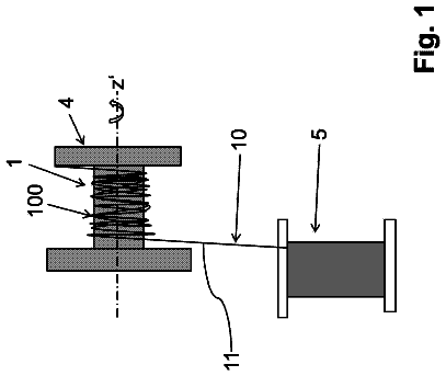
A coil is produced by winding a wire that is clad with an electrical insulation so as to form a coil bundle of successive windings.
US 11,211,686 B2 · Assignee: Dell Products, LP · Inventors: Ramasamy; Suresh K. et al.
Sheet 1 of 10 from the published document. All sheets in the USPTO PDF
An information handling system to wirelessly transmit and receive data at an antenna may include a base housing chassis containing components of the information handling system including a processor and memory and including a C-cover and a metal D-cover; a display chassis assembly having a display screen and including an A-cover; a hinge mechanically coupling the display chassis assembly to the base housing chassis; a hinge gap integrated along a hinge between an edge of the A-cover and an edge of the metal D-cover; an antenna to emit a radio frequency signal to a contained hinge gap resonant cavity formed within the hinge gap; and a flexible printed circuit (FPC) having a ground line operatively coupling the base housing chassis to the display chassis assembly to form a ground path across the hinge gap to shunt excitation currents along the hinge gap and to determine a size of the contained hinge gap resonant cavity between the A-cover and D-cover to accommodate an operating frequency of the radio frequency signal or harmonics of the operating frequency.
As the value and use of information continues to increase, individuals and businesses seek additional ways to process and store information. One option available to users is information handling systems. An information handling system generally processes, compiles, stores, and/or communicates information or data for business, personal, or other purposes thereby allowing users to take advantage of the value of the information. Because technology and information handling needs and requirements vary between different users or applications, information handling systems may also vary regarding what information is handled, how the information is handled, how much information is processed, stored, or communicated, and how quickly and efficiently the information may be processed, stored, or communicated. The variations in information handling systems allow for information handling systems to be
1 of 10 drawing sheets so far from the published document, cropped to the drawing. Every sheet is in the USPTO PDF.
What the patent claimed, word for word. All of it is now free to use.
The present disclosure generally relates to information handling systems, and more particularly relates to an information handling system including an antenna placed within a C-cover and D-cover assembly that uses a heat sink, hinge barrel, and flex cable to increase the operability of the antenna operatively coupled thereto.
As the value and use of information continues to increase, individuals and businesses seek additional ways to process and store information. One option available to users is information handling systems. An information handling system generally processes, compiles, stores, and/or communicates information or data for business, personal, or other purposes thereby allowing users to take advantage of the value of the information. Because technology and information handling needs and requirements vary between different users or applications, information handling systems may also vary regarding what information is handled, how the information is handled, how much information is processed, stored, or communicated, and how quickly and efficiently the information may be processed, stored, or communicated. The variations in information handling systems allow for information handling systems to be general or configured for a specific user or specific use such as financial transaction processing, airline reservations, enterprise data storage, or global communications. In addition, information handling systems may include a variety of hardware and software components that may be configured to process, store, and communicate information and may include one or more computer systems, data storage systems, and networking systems.
For purposes of this disclosure, an information handling system may include any instrumentality or aggregate of instrumentalities operable to compute, calculate, determine, classify, process, transmit, receive, retrieve, originate, switch, store, display, communicate, manifest, detect, record, reproduce, handle, or utilize any form of information, intelligence, or data for business, scientific, control, or other purposes. For example, an information handling system may be a personal computer (e.g., desktop or laptop), tablet computer, mobile device (e.g., personal digital assistant (PDA) or smart phone), server (e.g., blade server or rack server), a network storage device, or any other suitable device and may vary in size, shape, performance, functionality, and price. The information handling system may include random access memory (RAM), one or more processing resources such as a central processing unit (CPU) or hardware or software control logic, ROM, and/or other types of nonvolatile memory. Additional components of the information handling system may include one or more disk drives, one or more network ports for communicating with external devices as well as various input and output (I/O) devices, such as a keyboard, a mouse, touchscreen and/or a video display. The information handling system may also include one or more buses operable to transmit communications between the various hardware components. The information handling system may also include telecommunication, network communication, and video communication capabilities. The information handling system may also include one or more buses operable to transmit communications between the various hardware components. The information handling system may also include telecommunication, network communication, and video communication capabilities. Information handling system chassis parts may include case portions such as for a laptop information handling system including the C-cover over components designed with a metal structure. The information handling system may be configurable such that the information handling system may operate an antenna formed within a C-cover and D-cover assembly.
It will be appreciated that for simplicity and clarity of illustration, elements illustrated in the Figures are not necessarily drawn to scale. For example, the dimensions of some elements may be exaggerated relative to other elements. Embodiments incorporating teachings of the present disclosure are shown and described with respect to the drawings herein, in which:
FIG. 1 illustrates an embodiment of information handling system according to an embodiment of the present disclosure;
FIG. 2 is a block diagram of a network environment offering several communication protocol options and mobile information handling systems according to an embodiment of the present disclosure;
FIG. 3A is a graphical illustration perspective view of a metal chassis placed in a nearly closed configuration according to an embodiment of the present disclosure;
FIG. 3B is a graphical illustration perspective view of a metal chassis placed in the open configuration according to an embodiment of the present disclosure;
FIG. 3C is a graphical illustration top view of a metal hinge location between a display portion and a base portion of an information handling system according to an embodiment of the present disclosure;
FIG. 3D is another graphical illustration top view of a metal hinge location between a display portion and a base portion of an information handling system according to an embodiment of the present disclosure;
FIG. 3E is a graphical illustration side, cut-out view of a metal hinge location between a display portion and a base portion of an information handling system according to an embodiment of the present disclosure;
FIG. 4 is a graph showing values of return loss (in dBa) versus frequency of a RF wave according to an embodiment of the present disclosure;
FIG. 5 is showing values of return loss (in dBa) versus frequency of a RF wave according to an embodiment of the present disclosure;
FIG. 6 is a flow diagram illustrating a method for operating an information handling system having an antenna cavity with a flex cable according to an embodiment of the present disclosure;
FIG. 7 is a flow diagram illustrating a method of assembling an information handling system according to an embodiment of the present disclosure; and
FIG. 8 is a flow diagram illustrating a method of assembling an information handling system according to an embodiment of the present disclosure.
The use of the same reference symbols in different drawings may indicate similar or identical items.
The following description in combination with the Figures is provided to assist in understanding the teachings disclosed herein. The description is focused on specific implementations and embodiments of the teachings, and is provided to assist in describing the teachings. This focus should not be interpreted as a limitation on the scope or applicability of the teachings.
For aesthetic, strength, and performance reasons, information handling system chassis parts are more commonly designed with a metal structure. These metal structures are manufactured so as to have little or no sharp edges. During operation of an antenna, a metal chassis may be excited due to the metal structure and their conductive properties. Thus, the metal chassis do not have shape edges on them not only for aesthetic purposes but also so as to not provide, inadvertently, a location where radio frequency (RF) electromagnetic (EM) waves are propagated into space external to the information handling system.
In the embodiments described herein, a laptop information handling system may include a plurality of covers for the interior components of the information handling system. For example, a small form factor case may include an “A-cover” which serves as a back cover for a display housing and a “B-cover” which may serve as the bezel, if any, and a display screen of the convertible laptop information handling system in an embodiment. Together, the A-cover and B-cover may be assembled together to form a display portion of the information handling system (herein also described as an “A-cover/B-cover assembly”). In a further example, the laptop information handling system case may include a “C-cover” housing a keyboard, touchpad, and any cover in which these components are set and a “D-cover” base housing for the convertible information handling system. Together, the C-cover and D-cover may be assembled together to form a base portion of the information handling system (herein also described as a “C-cover/D-cover” assembly). With the need for utility of lighter, thinner, and more streamlined devices, the use of full metal portions for the outer covers of the display and base housing (e.g. the A-cover and the D-cover) is desirable for strength as well as aesthetic reasons. At the same time, the demands for wireless operation also increase. This includes addition of many simultaneously operating radiofrequency systems, addition of more antennas, and utilization of various antenna types. In addition to the use of metal chassis in a metal conductive information handling system, the thinner and more streamlined devices have fewer locations and areas available for mounting radiofrequency transmitters on these mobile information handling systems. Thus, a streamlined, full metal chassis capable of meeting the increasing wireless operation demands is described herein that allows for the increase in the size of the video display device as well as antenna systems.
Previous information handling systems would address these competing needs by providing for cutout portions of a metal outer chassis cover filled with plastic behind which radio transmitters would be mounted. The cutouts to accommodate radio frequency (RF) transmitters were often aesthetically undesirable and required additional plastic components to cover the cutout, thus failing to fully meet the streamlining needs. The plastic components added a component to be manufactured and were required to be seamlessly integrated into an otherwise smooth metal chassis cover. Further, the plastic portions included may be more expensive to machine than aluminum alloy metals, and may require intricate multi-step processes for integrating the metal and plastic parts into a single chassis. This requirement could require difficult and expensive processes to manufacture with a less desirable result. Other options included, for aperture type antenna transmitters, creation of an aperture in the metal display panel chassis and using the metal chassis as a ground plane for excitation of the aperture. Similarly, the visible apertures in the chassis cover were also less desirable, and the RF transmission hotspot would be located on the metal chassis cover itself. In the present specification and in the appended claims, the term “aperture” is meant to be understood as a physical gap or an opening oriented perpendicular to the direction of any transmitted or received electromagnetic (EM) wave that transmits and receives the same amount of power from those waves as that produced by an antenna. In some embodiments described herein, the aperture may be defined by an opening, such as in a chamber within a rotation portion formed as part of the drop barrel hinge. In another aspect, an aperture may be formed as part of an aesthetics or identification feature and may be formed as part of the hinge edge coupling points, the drop barrel hinge edge of the A-cover itself, a flex cable, portions of the C-cover/D-cover assembly, and/or other portions of the A-cover/B-cover assembly. In other embodiments, the space formed along the drop barrel hinge gap including the hinge edge coupling points, the drop barrel hinge edge of the A-cover itself, a flex cable, portions of the C-cover/D-cover assembly, and/or other portions of the A-cover/B-cover assembly may serve as a resonant cavity which works with the transceiving antenna which may be another aperture or a planar wire antenna in some embodiments.
In addition, in the case of a convertible laptop information handling system, 135- to 180-degree configurability may be a feature available to a user during use. Thus, often an antenna such as an aperture antenna system would be located at the top (e.g. “A-cover”) with a plastic antenna window in a metal chassis cover to radiate in such as closed mode. Such a configuration would make the display panel housing (e.g. “A-cover”) thicker, to accommodate antennas and cables behind the plastic panel at the top (or bottom) of either housing. Overall, a thicker convertible laptop information handling system would result, thus failing to meet the streamlining needs. A solution is needed that does not increase the thickness of the metal chassis, and does not require additional components and manufacturing steps such as those associated with installation of RF transparent windows.
Embodiments of the present disclosure may decrease the complexity and cost of creating chassis for information handling systems by forming the outer chassis (e.g. the A-cover and the D-cover) entirely of metal and providing for an antenna formed within the D-cover and C-cover assembly. This placement of the antenna into a location near a heat sink and near or within a hinge barrel assembly may allow for the grounding of certain RF EM waves that may excite the metal chassis and/or cause destructive interference of the RF EM waves propagated by the antenna. In an embodiment, a hinge gap may be formed between the A-cover and D-cover. The hinge gap causes any radio frequency (RF) electromagnetic (EM) radiation emitted from the antenna to also resonate therein when the antenna is located nearby because the hinge is made of metal. In one embodiment, a planar wire antenna may be located in a base chassis near the hinge of an information handling system such as a laptop information handling system with a drop barrel hinge. The planar wire antenna may transmit at a desired frequency but may incur resonance along a hinge gap of the drop barrel hinge between a metal A-cover and metal D-cover. This planar wire antenna of some embodiments may excite ground currents in the base chassis and keyboard surface of the C-cover and D-cover. Such resonance, especially along the hinge gap may be mitigated in some embodiments with a grounding cable as part of a flex cable for communications between the base chassis and display chassis across the hinge gap.
An aperture antenna, in certain other embodiments, can also be located near the A-cover to D-cover hinge gap. In such embodiments, the aperture antenna may be located in the drop barrel hinge and excite ground currents on the A-cover and hinge barrel as well as along a hinge gap formed between the A-cover and D-cover of the information handling system. In this embodiment, the hinge gap may be sized to form an aperture for the aperture antenna of the barrel hinge. The length of the hinge gap apertures may be sized in width by dimension of the gap and in length by the edge of the hinge gap and the position of a flex cable or other communication cable to extend a ground path across the hinge gap. Similar to the above embodiment, a flex cable or other communication cable across the hinge gap with grounding capability may also contain resonance of currents further along the hinge gap or elsewhere in the A-cover, barrel hinge, or base chassis to also regulate the radiation path of the antenna system.
In an embodiment of the present disclosure, an antenna aperture may be located in a hinge portion of the information handling system and formed within the hinge gap. In an embodiment for example, an antenna aperture may be located in a drop barrel hinge forming part of the A-cover and along a gap formed between the hinge barrel and D-cover. In the embodiments described herein, the drop barrel hinge is a portion of the A-cover hinged at the sides to the D-cover. The drop barrel hinge may drop back in the middle of the display portion when the laptop-type information handling system is placed in an open configuration.
In another embodiment, an antenna element may be located in a configurable cavity formed within the base chassis. This configurable cavity may house, in an embodiment a heat sink used to direct heat away from the information handling system. In such an embodiment, the base chassis may house a planar wire antenna that is located under the C-cover along the base chassis near the hinge gap. In yet other embodiments, an aperture antenna may be formed in the base chassis and transcieve RF EM waves near a hinge gap. In these types of antenna elements or aperture antenna locations near a hinge gap of a drop barrel hinge, resonance of transceived wireless signals may extend down the hinge gap or across the metallic surfaces of the C-cover, D-cover, A-cover, or hinge elements. Such unchecked resonance may deplete the wireless signal, cause polluting noise to information handling system elements, or interfere with the tranceived signal or other signals transcieved at other antenna systems of the information handling system.
In either embodiment, a flexible printed circuit (FPC) or any other type of flexible flat cable (FFC) may be formed across a configurable cavity at a location along the hinge gap so as to shunt any surface currents from reaching the components placed within the base chassis or display chassis or to contain currents from further travel down the hinge gap. During operation of the antenna elements, a hinge aperture antenna or a base chassis planar wire antenna for example as described herein, the RF EM waves emitted therefrom may interact with the metallic surfaces of the base chassis and display chassis causing currents to form. The FPC may be situated so as to help ground those currents before they propagate throughout the information handling system and further along the cavity formed of the hinge gap. In some embodiments, a grounding path may be formed to also direct those current to a grounding surface such as the D-cover where it can be dispersed without causing reduced signal or interference with the components of the information handling system. In an embodiment, a parasitic element may be used to direct those currents from the antenna element through a heat vent in the configurable cavity and to the D-cover. In other aspects, a parasitic element may be used to assist aperture antenna operation of the aperture antenna located in a drop hinge of the A-cover.
During operation of the antenna, whether the antenna is placed in the base portion or in the drop barrel hinge, the RF EM emissions by an antenna at the hinge gap may control, reduce, or eliminate resonances within the hinge gap with a flexible printed circuit or flexible flat cable or other grounding line across the hinge gap. In embodiments where multiple antennas are employed within the information handling system, any gap resonance may also cause cross-talk between the plurality of antennas. The gap resonance created by the hinge gap also creates directionality issues with regards to RF electromagnetic emissions. In some embodiments presented herein, the information handling system may include a ground wire in the form of a high-speed flex cable, a flexible printed circuit (FPC), a flexible flat cable (FFC), or other type of power or communication cable. The specific placement of the flex cable across the hinge gap forms a specific directional aperture along the hinge gap and helps to ground any excitation currents formed by the operation of the antenna element or antenna aperture from resonating further along the hinge gap or resonating elsewhere in the information handling system chassis. As a result, a relatively more focused transmission and reception power at frequencies that are emitted by the antenna element from a base chassis or an antenna aperture in a drop hinge barrel and its aperture along the hinge gap may be achieved.
The metal chassis in embodiments described herein may include a hinge operably connecting the “A-cover” to the “D-cover” such that the keyboard and touchpad enclosed within the “C-cover” and attached to the “D-cover” of the base portion of the information handling system may be placed in a plurality of configurations with respect to the digital display enclosed within the “B-cover” and attached to the “A-cover.” The plurality of configurations may include, but may not be limited to, an open configuration in which the “A-cover” is oriented at a right or obtuse angle from the “D-cover” (similar to an open laptop computer) and a closed configuration in which the “A-cover” lies substantially parallel to the “D-cover” (similar to a closed laptop computer) such that the user can interact with the digital display enclosed within the “B-cover”). Despite these different configurations, however, the antenna cavity within a hinge barrel or formed near the hinge barrel and by the heat sink provides for the streamlining of the information handling system without compromising the ability of the antenna or antenna aperture to transmit and receive data from and to the information handling system.
Manufacture of embodiments of the present disclosure may involve fewer extraneous parts than previous chassis by forming the exterior or outer portions of the information handling system, including, at least, the bottom portion of the “D-cover” and the top portion of the “A-cover,” in some embodiments, entirely from metal. In order to allow for manufacture of fully metallic outer chassis including the “A-cover” and the “D-cover,” embodiments of the present disclosure form the full form factor case enclosing the information handling system such that one or more transmitting antennas within the antenna cavity integrated into a hinge barrel and base metal chassis (i.e., “D-cover”) of the information handling system.
The transmitting antennas of embodiments of the present disclosure may include aperture antennas. Aperture antennas in embodiments of the present disclosure may be a highly effective improvement on wireless antennas employed in previous information handling systems. In embodiments of the present disclosure, an antenna aperture or slot may be placed in a location near or within the hinge barrel that mechanically couples the A-cover/B-cover assembly to the C-cover/D-cover assembly or may form part of the A-cover/B-cover assembly so as to couple the A-cover/B-cover to the C-cover/D-cover assembly of the information handling system. An aperture associated with the antenna in embodiments of the present disclosure may then be operably connected to grounding walls and/or grounding paths such that the RF EM signals reduce or limit exciting structures by the antennas that are not used for radiating wireless signals. Such a method of placing an aperture associated with the antenna at this location of the form factor case may exclude the integration of any RF transparent plastic windows within the exterior of “D-cover” or any other cover of the information handling system itself, thus decreasing the complexity and cost of manufacture. The antenna may then effectively transmit communications signal perpendicularly from, for example, the surface of the “D-cover” such as along a hinge gap between the D-cover and the A-cover. When the “D-cover” and “A-cover” are placed in either the open configuration the antenna in such an embodiment may transmit the communications signals away from the information handling system and into the nearby environment. When the “D-cover” and “A-cover” are placed in the closed configuration, the antenna may transmit and receive the communications signal out from the “D-cover” still allowing for transmission and receipt of data via the antenna.
Embodiments of the present disclosure may also allow the antenna to operate at higher power levels in the presence of human body parts than previous information handling systems with antennas located in the base housing chassis or “D-cover.” The Federal Communications Commission (FCC) regulates the strength of radio frequency signals of an LTE antenna or other antenna systems within a commercial product sold in the United States may emit. Higher strength radio frequency signals may result in stronger signals and better communication, but may also increase the specific absorption rate (SAR), or rate at which energy is absorbed by the human body. The FCC requires LTE antennas within US commercial products to lower the power supplied to the LTE antenna when the antenna is in close proximity to a human body part in order to avoid any increase in SAR. The requirement of power reduction depends on hotspot radiofrequency SAR levels detected around the information handling system where a user may come into contact. Power reduction however may also have an adverse effect on radiofrequency system performance. SAR levels drop off significantly however with distance from an active transmitter. Thus, an antenna transmitter location and design where the active transmission element may be located further away from any surfaces potentially contacted by a user's body parts may not require as much power reduction.
In embodiments described herein, an antenna aperture of the “D-cover” may lie vertically lower than the keyboard of the “C-cover,” which is the surface most likely to interface with human body parts. In such embodiments, placement of the transmitting antenna beneath the “C-cover” may place the antenna further away from human body parts than an information handling system placing the transmitting antenna directly beneath, alongside, or co-planar with the keyboard. However, a planar wire antenna or aperture antenna under the C-cover or along a back wall of the base chassis or an aperture antenna in a drop barrel hinge may avoid radiofrequency signals in the bottom D-cover which may be in contact with a user's lap and for which SAR levels may be carefully monitored. In some embodiments, an antenna element or antenna aperture may be formed in a location below the C-cover and near the hinge barrel or in the hinge barrel potentially creating a cavity at the hinge gap that re-radiates any RF signals (i.e., any type of electromagnetic radiation) therein. This cavity may limit the spread of the surface currents within the selected aperture antenna or reduce the effectiveness of a planar wire antenna element. Such reduction of RF radiation beyond the antenna element or antenna aperture may, at the A-cover and C-cover gap, decrease the radiation emitted outside the cavity. Accordingly, control of the signal transmitted via an antenna element or antenna aperture may be directed up towards the horizon with control of resonance at the hinge gap thereby improving a signal transmitted via the antenna aperture. Thus, smaller reductions in power supplied to the transmitter may be used in order to comply with FCC SAR regulations while providing similar or improved wireless signaling in such embodiments.
In some embodiments described herein, an antenna aperture may be formed, at least, partially within the hinge barrel. In such embodiments, placement of the transmitting antenna within the hinge barrel may also place the antenna further away from human body parts than an information handling system placing the transmitting antenna directly beneath, alongside, or co-planar with the keyboard. In some embodiments, an antenna cavity may be formed in a location below the C-cover and near the hinge barrel potentially creating a cavity that re-radiates any RF signals (i.e., any type of electromagnetic radiation) therein from the aperture antenna of the hinge barrel. This cavity may limit the spread of the surface currents within the aperture antenna if limitation of resonance down the hinge gap is limited as described. Such reduction of RF radiation beyond the antenna aperture and cavity intended to radiate the EM RF signal may, at the A-cover and C-cover gap, decrease the radiation emitted outside the cavity. As a result, the SAR of the signal transmitted via an antenna aperture may be directed up towards the horizon along the portion of the hinge gap desired for radiation or RF signals thereby improving a signal transmitted via the antenna aperture. Thus, smaller reductions in power supplied to the transmitter may be used in order to comply with FCC SAR regulations while providing similar or improved wireless signaling in such embodiments.
Examples are set forth below with respect to particular aspects of an information handling system including case portions such as for a laptop information handling system including the chassis components designed with a fully metal structure and configurable such that the information handling system may operate in any of several usage mode configurations.
FIG. 1 shows an information handling system 100 capable of administering each of the specific embodiments of the present disclosure. The information handling system 100 , in an embodiment, can represent the mobile information handling systems 210 , 220 , and 230 or servers or systems located anywhere within network 200 described in connection with FIG. 2 herein, including the remote data centers operating virtual machine applications. Information handling system 100 may represent a mobile information handling system associated with a user or recipient of intended wireless communication. A mobile information handling system may execute instructions via a processor such as a microcontroller unit (MCU) operating both firmware instructions or hardwired instructions for the antenna adaptation controller 134 to achieve WLAN or WWAN antenna optimization according to embodiments disclosed herein. The application programs operating on the information handling system 100 may communicate or otherwise operate via concurrent wireless links, individual wireless links, or combinations over any available RAT protocols including WLAN protocols. These application programs may operate in some example embodiments as software, in whole or in part, on an information handling system while other portions of the software applications may operate on remote server systems. The antenna adaptation controller 134 of the presently disclosed embodiments may operate as firmware or hardwired circuitry or any combination on controllers or processors within the information handing system 100 for interface with components of a wireless interface adapter 120 . It is understood that some aspects of the antenna adaptation controller 134 described herein may interface or operate as software or via other controllers associated with the wireless interface adapter 120 or elsewhere within information handling system 100 . Information handling system 100 may also represent a networked server or other system from which some software applications are administered or which wireless communications such as across WLAN or WWAN may be conducted. In other aspects, networked servers or systems may operate the antenna adaptation controller 134 for use with a wireless interface adapter 120 on those devices similar to embodiments for WLAN or WWAN antenna optimization operation according to according to various embodiments.
The information handling system 100 may include a processor 102 such as a central processing unit (CPU), a graphics processing unit (GPU), or both. Moreover, the information handling system 100 may include a main memory 104 and a static memory 106 that can communicate with each other via a bus 108 . As shown, the information handling system 100 may further include a video display unit 110 , such as a liquid crystal display (LCD), an organic light emitting diode (OLED), a flat panel display, or a solid-state display. Display 110 may include a touch screen display module and touch screen controller (not shown) for receiving user inputs to the information handling system 100 . Touch screen display module may detect touch or proximity to a display screen by detecting capacitance changes in the display screen as understood by those of skill. Additionally, the information handling system 100 may include an input device 112 , such as a keyboard, and a cursor control device, such as a mouse or touchpad or similar peripheral input device. The information handling system may include a power source such as battery 114 or an A/C power source. The information handling system 100 can also include a disk drive unit 116 , and a signal generation device 118 , such as a speaker or remote control. The information handling system 100 can include a network interface device such as a wireless adapter 120 . The information handling system 100 can also represent a server device whose resources can be shared by multiple client devices, or it can represent an individual client device, such as a desktop personal computer, a laptop computer, a tablet computer, a wearable computing device, or a mobile smart phone, among other computing devices.
The information handling system 100 can include sets of instructions 124 that can be executed to cause the computer system to perform any one or more desired applications. In many aspects, sets of instructions 124 may implement wireless communications via one or more antenna systems 132 available on information handling system 100 . Operation of WLAN and WWAN wireless communications may be enhanced or otherwise improved via WLAN or WWAN antenna operation adjustments via the methods or controller-based functions relating to the antenna adaptation controller 134 described herein. For example, instructions or a controller may execute software or firmware applications or algorithms which utilize one or more wireless links for wireless communications via the wireless interface adapter as well as other aspects or components.
The antenna adaptation controller 134 may execute instructions as disclosed herein for monitoring wireless link state information, information handling system configuration data, SAR proximity sensor detection, or other input data to generate channel estimation and determine antenna radiation patterns. In the embodiments presented herein, the antenna adaptation controller 134 may execute instructions as disclosed herein to transmit a communications signal from an antenna located near a hinge barrel between the A-cover/B-cover assembly or a display portion and C-cover/D-cover assembly of the base portion of the information handling system. The execution of these instructions may create a resonant frequency at an aperture of the antenna cavity in a hinge gap there between to transmit an electromagnetic wave at a determined frequency or harmonics thereof. The antenna aperture cavity system of the embodiments herein may prevent noise caused due to the excitation of the display and base portion hinge gap outside the antenna cavity from creating interference with the determined frequency, or harmonics thereof, and reflecting transmission or receiving power for the antenna system.
In embodiments herein, a grounding system may be created at and within the antenna aperture cavity. In the embodiments presented herein, the antenna adaptation controller 134 may execute instructions as disclosed herein to adjust, via a parasitic element, a directionality and/or pattern of the emitted RF signals from the antenna. The antenna adaptation controller 134 may implement adjustments to wireless antenna systems and resources via a radio frequency integrated circuit (RFIC) front end 125 and WLAN or WWAN radio module systems within the wireless interface device 120 . Aspects of the antenna optimization for the antenna adaptation controller 134 may be included as part of an antenna front end 125 in some aspects or may be included with other aspects of the wireless interface device 120 such as WLAN radio module or as part of the radio frequency subsystems 130 . The antenna adaptation controller 134 described in the present disclosure and operating as firmware or hardware (or in some parts software) may remedy or adjust one or more of a plurality of antenna systems 132 via selecting power adjustments and adjustments to an antenna adaptation network to modify antenna radiation patterns and parasitic element operations according to some embodiments herein. Multiple WLAN or WWAN antenna systems may operate on various communication frequency bands such as under IEEE 802.11a and IEEE 802.11g providing multiple band options for frequency channels. Further antenna radiation patterns and selection of antenna options or power levels may be adapted due physical proximity of other antenna systems, of a user with potential SAR exposure, or improvement of RF channel operation according to received signal strength indicator (RSSI), signal to noise ratio (SNR), bit error rate (BER), modulation and coding scheme index values (MCS), or data throughput indications among other factors. In some aspects WLAN antenna adaptation controller may execute firmware algorithms or hardware to regulate operation of the one or more antenna systems 132 such as WLAN antennas in the information handling system 100 to avoid poor wireless link performance due to poor reception, poor MCS levels of data bandwidth available, or poor indication of throughput due to indications of low RSSI, low power levels available (such as due to SAR), inefficient radiation patterns among other potential effects on wireless link channels used.
Various software modules comprising software application instructions 124 or firmware instructions may be coordinated by an operating system (OS) and via an application programming interface (API). An example operating system may include Windows®, Android®, and other OS types known in the art. Example APIs may include Win 32 , Core Java API, Android APIs, or wireless adapter driver API. In a further example, processor 102 may conduct processing of mobile information handling system applications by the information handling system 100 according to the systems and methods disclosed herein which may utilize wireless communications. The computer system 100 may operate as a standalone device or may be connected such as using a network, to other computer systems or peripheral devices. In other aspects, additional processor or control logic may be implemented in graphical processor units (GPUs) or controllers located with radio modules or within a wireless adapter 120 to implement method embodiments of the antenna adaptation controller and antenna optimization according to embodiments herein. Code instructions 124 in firmware, hardware or some combination may be executed to implement operations of the antenna adaptation controller and antenna optimization on control logic or processor systems within the wireless adapter 120 for example.
In a networked deployment, the information handling system 100 may operate in the capacity of a server or as a client user computer in a server-client user network environment, or as a peer computer system in a peer-to-peer (or distributed) network environment. The information handling system 100 can also be implemented as or incorporated into various devices, such as a personal computer (PC), a tablet PC, a set-top box (STB), a PDA, a mobile information handling system, a tablet computer, a laptop computer, a desktop computer, a communications device, a wireless smart phone, wearable computing devices, a control system, a camera, a scanner, a printer, a personal trusted device, a web appliance, a network router, switch or bridge, or any other machine capable of executing a set of instructions (sequential or otherwise) that specify actions to be taken by that machine. In a particular embodiment, the computer system 100 can be implemented using electronic devices that provide voice, video or data communication. Further, while a single information handling system 100 is illustrated, the term “system” shall also be taken to include any collection of systems or sub-systems that individually or jointly execute a set, or multiple sets, of instructions to perform one or more computer functions described herein.
The description continues in the full USPTO document.
About 6,230 words. The USPTO PDF has it with every drawing.
Fees are due 3.5, 7.5 and 11.5 years after grant. This patent expired on December 28, 2025, so the fee marked "not paid" was the one that went unpaid.
SYSTEM AND METHOD FOR OPERATION OF A HINGE CAVITY ANTENNA
Filed Dec 2019 · published Jun 2021System and method for operation of a hinge cavity antenna
Filed Dec 2019 · granted Dec 2021Earlier publications, parents and continuations. None of them can still be enforced, or this patent would not be listed.
Prior art cited by the examiner or applicant. Useful when you check your own idea for novelty.
Everything on this page comes from the documents linked above.