Cross-reference to related application
This application claims priority to and the benefit of Korean Patent Application No. 10-2018-0126604 filed on Oct. 23, 2018, the entire contents of which are incorporated herein by reference. BACKGROUND (a) Field of the Invention
The present invention relates to a heat pump system for a vehicle, and more particularly, to a heat pump system for a vehicle that cools a battery module and improves heating efficiency by recovering waste heat of electrical equipment and the battery module, by using a single chiller in which a refrigerant and a coolant are heat-exchanged. (b) Description of the Related Art
Generally, an air conditioner for a vehicle includes an air conditioner system that circulates a refrigerant to heat or cool an interior of the vehicle. The air conditioner system, which maintains a fresh indoor condition by maintaining an indoor temperature of a vehicle at an appropriate temperature regardless of an outdoor temperature change, is configured to heat or cool an interior of the vehicle by heat-exchange using an evaporator during a process in which a refrigerant discharged by driving a compressor is circulated to the compressor again by passing through a condenser, a receiver drier, an expansion valve, and the evaporator. In other words, in the air conditioner system, a high-temperature and high-pressure gaseous refrigerant compressed by the compressor is condensed through the condenser, then is evaporated by the evaporator through the receiver drier and the expansion valve to reduce the indoor temperature and humidity in a summer cooling mode.
Recently, as concerns regarding energy efficiency and environmental pollution have gradually increased, development of an environmentally friendly vehicle capable of being substantially substituted for a vehicle having an internal combustion engine has been developed, and the environmentally friendly vehicles are typically classified into an electric vehicle which is typically driven using a fuel cell or electricity as a power source, and a hybrid vehicle which is driven using an engine and an electric battery.
In the electric vehicle and the hybrid vehicle of the environmentally friendly vehicles, a separate heater is omitted, unlike a general vehicle that uses an air conditioner, and an air conditioner which is applied to the environmentally friendly vehicle is typically referred to as a heat pump system. For the electric vehicle that uses the fuel cell, chemical reaction energy of oxygen and hydrogen is converted into electrical energy to generate driving force, and during this process, heat energy is generated by chemical reaction in the fuel cell, and as a result, effective removal of the generated heat is required to secure the performance of the fuel cell.
Even in the hybrid vehicle, the driving force is generated by driving the motor using electricity supplied from the fuel cell or the electric battery together with the engine that is actuated with a general fuel, and as a result, the performance of the motor may be secured only by effectively removing the heat generated from the fuel cell or the battery, and the motor. Accordingly, in a hybrid vehicle or electric vehicle of a prior art, a battery cooling system, a cooling part, and a heat pump system should be configured to have respective separate circuits to prevent heat generation of a motor, electrical equipment, and a battery including a fuel cell.
Thus, the size and weight of a cooling module disposed in the front of the vehicle are increased, and a layout of connecting pipes for supplying a refrigerant or coolant to the heat pump system, the cooling part, and the battery cooling system inside an engine compartment becomes complex. In addition, since the battery cooling system that heats or cools the battery is provided separately based on a state of the vehicle and thus, the battery may operate in an optimal state, a plurality of valves that connect the respective connecting pipes are applied, thus noise and vibration are transmitted to the interior of the vehicle, resulting in poor ride comfort.
The above information disclosed in this section is merely for enhancement of understanding of the background of the invention, and therefore it may contain information that does not form the prior art that is already known in this country to a person of ordinary skill in the art.
Summary
The present invention has been made in an effort to provide a heat pump system for a vehicle that may cool a battery module using a single chiller in which a coolant and a refrigerant are heat-exchanged, and may simplify a system therefor by applying an integrated control valve configured to adjust a flow of a refrigerant to reduce the number of valves. In addition, the present invention has been made in an effort to provide a heat pump system for a vehicle that may improve heating efficiency using another chiller that recovers waste heat of electrical equipment and the battery module.
An exemplary embodiment of the present invention provides a heat pump system for a vehicle that may include: a battery coolant line configured to be connected to a battery module and into which a coolant flows; a cooling device configured to include a radiator and a first water pump connected to a coolant line, to circulate a coolant in the coolant line to cool electrical equipment, and to be selectively connected to the battery coolant line via a first valve; a chiller disposed in the battery coolant line, to be connected to a refrigerant line of an air conditioner via a connecting line, and to adjust a temperature of a coolant or to increase a temperature of a refrigerant by selectively exchanging heat between the coolant and the refrigerant flowing into the chiller; and an integrated control valve configured to be connected to the refrigerant line and the connecting line to adjust a flow direction of a refrigerant circulated in the air conditioner and to selectively expand a refrigerant passing through the inside of the integrated control valve.
The air conditioner may include: a heating, ventilation, and air conditioning (HVAC) module connected to the air conditioner via the refrigerant line and an opening/closing door is disposed within the HVAC so that outside air passing through an evaporator selectively flows into an internal condenser based on cooling, heating, and heating/dehumidifying modes of the vehicle; a compressor connected between the evaporator and the internal condenser via the refrigerant line; an accumulator disposed in the refrigerant line between the compressor and the evaporator; a first condenser connected to the internal condenser via the refrigerant line and disposed inside of the radiator; a second condenser connected to the first condenser via the refrigerant line and disposed in the front of the vehicle; and an expansion valve disposed in the refrigerant line that connects the second condenser and the evaporator.
The refrigerant line that connects the internal condenser and the first condenser and the refrigerant line that connects the second condenser and the evaporator may be respectively connected to the integrated control valve. The connecting line may be connected to the accumulator to allow a refrigerant passing through the chiller to be supplied to the accumulator.
A sub-heat exchanger may be disposed between the evaporator and the accumulator, and the refrigerant line that connects the integrated control valve and the expansion valve and the refrigerant line that connects the evaporator and the accumulator may be respectively connected to the sub-heat exchanger. The sub-heat exchanger may be a dual pipe heat exchanger. The sub-heat exchanger may be configured to condense a refrigerant condensed in the second condenser through heat-exchange with a low-temperature refrigerant discharged from the evaporator to flow into the expansion valve. When the battery module is cooled using the refrigerant, the integrated control valve may expand a refrigerant supplied from the second condenser through the refrigerant line and then may discharge the refrigerant to the connecting line to allow the refrigerant to flow into the chiller.
The first valve may be disposed between the radiator and the chiller to selectively connect the coolant line connected to the electrical equipment and the battery coolant line connected to the battery module, a first branch line may be disposed in the battery coolant line. The first branch line may be connected to the battery coolant line via the first valve and may selectively connect the chiller and the battery module based on an operation of the first valve, a second valve may be disposed in the coolant line between the electrical equipment and the radiator, a third valve that selectively connects the battery coolant line may be disposed in the coolant line into which a coolant discharged from the radiator flows, a second branch line that connects the radiator and the electrical equipment via the third valve may be disposed in the coolant line that connects between the electrical equipment and the first valve, and a third branch line that is selectively connected to the coolant line via the second valve and configured to circulate a coolant passing through the electrical equipment to the coolant line connected thereto through the second valve without passing through the radiator may be provided.
When the battery module is cooled, the first valve and the third valve may block connection of the refrigerant line and the battery coolant line, and may open the first and second branch lines. In the heating mode or the heating/dehumidifying mode of the vehicle, the third branch line may be opened through an operation of the second valve. A reservoir tank may be disposed in the refrigerant line between the radiator and the third valve, and the reservoir tank may be connected to the third branch line, and may be connected to the first branch line via a degassing line.
In particular, the degassing line may discharge bubbles generated in a coolant passing through the first branch line into the reservoir tank and thus, a pressure balance between the coolant line and the battery coolant line may be maintained. Alternatively, the degassing line may allow bubbles generated and collected in the coolant circulating in the coolant line to flow into the first branch line. The chiller may be selectively connected to the coolant line through the third branch line opened through an operation of the second valve to recover waste heat generated from the electrical equipment or from the electrical equipment and the battery module in the heating mode of the vehicle. The first condenser may be a water-cooled heat exchanger, and the second condenser may be an air-cooled heat exchanger.
The integrated control valve may open the connecting line in the heating mode or the heating/dehumidifying mode of the vehicle when cooling the battery module using the refrigerant in the cooling mode of the vehicle, and the integrated control valve may close the connecting line connected to the chiller when the cooling of the battery module is not required in the cooling mode of the vehicle. A second water pump may be disposed in the battery coolant line between the chiller and the battery module, a heater may be disposed in the battery coolant line between the battery module and the chiller, and the heater may be turned on while a temperature of the battery module is increased, and thus, the coolant circulating in the battery coolant line may be heated to flow into the battery module.
According to a heat pump system for a vehicle of an exemplary embodiment of the present invention, it may be possible to simplify a system for the heat pump system for the vehicle by using a single chiller in which a coolant and a refrigerant are heat-exchanged to cool a battery module in an electric vehicle or a hybrid vehicle. In addition, according to an exemplary embodiment of the present invention, since a battery module may be efficiently heated and cooled according to a mode of a vehicle, it may be possible to operate the battery module at optimal performance, and total mileage of the vehicle may be increased through efficient management of the battery module.
Further, according to an exemplary embodiment of the present invention, it may be possible to reduce the number of valves for adjusting a flow of a refrigerant by applying an integrated control valve for adjusting the flow of the refrigerant. In addition, according to the exemplary embodiment of the present invention, the single chiller may selectively recover the waste heat of the electrical equipment and the battery module, thereby reducing the power consumption of the compressor and improving the heating efficiency. Moreover, according to a heat pump system for a vehicle of an exemplary embodiment of the present invention, by simplifying an entire system related thereto, it may be possible to reduce manufacturing costs and weight, and to improve space utilization.
Brief description of the drawings
The above and other features of the present invention will now be described in detail with reference to certain exemplary embodiments thereof illustrated the accompanying drawings which are given hereinbelow by way of illustration only, and thus are not limitative of the present invention, and wherein:
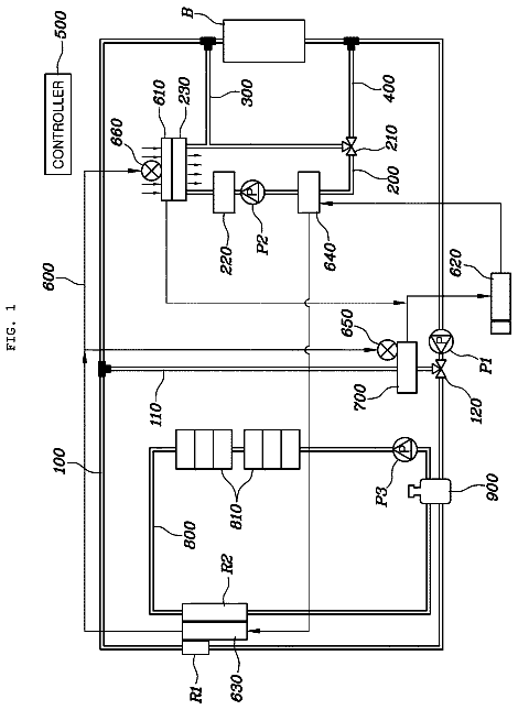
FIG. 1 illustrates a block diagram of a heat pump system for a vehicle according to an exemplary embodiment of the present invention;
FIG. 2 illustrates an operational state diagram of a cooling mode of a vehicle in a heat pump system for the vehicle according to an exemplary embodiment of the present invention;
FIG. 3 illustrates an operational state diagram of a heating mode of a vehicle in a heat pump system for the vehicle according to an exemplary embodiment of the present invention;
FIG. 4 illustrates an operational state diagram for cooling a battery module using a refrigerant in a heat pump system for a vehicle according to an exemplary embodiment of the present invention;
FIG. 5 illustrates an operational state diagram for cooling a battery module in a cooling mode of a vehicle in a heat pump system for the vehicle according to an exemplary embodiment of the present invention;
FIG. 6 illustrates an operational state diagram of a heating/dehumidifying mode in a heat pump system for a vehicle according to an exemplary embodiment of the present invention; and
FIG. 7 illustrates an operational state diagram for cooling a battery module in a heating/dehumidifying mode in a heat pump system for a vehicle according to an exemplary embodiment of the present invention.
Description of symbols
1 : heat pump system 10 : cooling device 11 : coolant line 12 : radiator 13 : cooling fan 14 : first water pump 15 : electrical equipment 16 : reservoir tank 20 : air conditioner 21 : refrigerant line 22 : HVAC module 23 : internal condenser 25 : internal heater 27 : evaporator 29 : opening/closing door 31 : compressor 33 : accumulator 34 : integrated control valve 35 : first condenser 37 : second condenser 39 : expansion valve 101 : battery coolant line 103 : second water pump 110 : chiller 111 : connecting line 120 , 130 , 140 : first, second, third branch line 150 : degassing line B: battery module V 1 , V 2 , V 3 : first, second, third valve DETAILED DESCRIPTION
It is understood that the term “vehicle” or “vehicular” or other similar term as used herein is inclusive of motor vehicles in general such as passenger automobiles including sports utility vehicles (SUV), buses, trucks, various commercial vehicles, watercraft including a variety of boats and ships, aircraft, and the like, and includes hybrid vehicles, electric vehicles, plug-in hybrid electric vehicles, hydrogen-powered vehicles and other alternative fuel vehicles (e.g. fuels derived from resources other than petroleum). As referred to herein, a hybrid vehicle is a vehicle that has two or more sources of power, for example both gasoline-powered and electric-powered vehicles.
Although exemplary embodiment is described as using a plurality of units to perform the exemplary process, it is understood that the exemplary processes may also be performed by one or plurality of modules. Additionally, it is understood that the term controller/control unit refers to a hardware device that includes a memory and a processor. The memory is configured to store the modules and the processor is specifically configured to execute said modules to perform one or more processes which are described further below.
The terminology used herein is for the purpose of describing particular embodiments only and is not intended to be limiting of the invention. As used herein, the singular forms “a”, “an” and “the” are intended to include the plural forms as well, unless the context clearly indicates otherwise. It will be further understood that the terms “comprises” and/or “comprising,” when used in this specification, specify the presence of stated features, integers, steps, operations, elements, and/or components, but do not preclude the presence or addition of one or more other features, integers, steps, operations, elements, components, and/or groups thereof. As used herein, the term “and/or” includes any and all combinations of one or more of the associated listed items.
Unless specifically stated or obvious from context, as used herein, the term “about” is understood as within a range of normal tolerance in the art, for example within 2 standard deviations of the mean. “About” can be understood as within 10%, 9%, 8%, 7%, 6%, 5%, 4%, 3%, 2%, 1%, 0.5%, 0.1%, 0.05%, or 0.01% of the stated value. Unless otherwise clear from the context, all numerical values provided herein are modified by the term “about.”
An exemplary embodiment of the present invention will hereinafter be described in detail with reference to the accompanying drawings. Since the exemplary embodiment described in the specification and the configurations shown in the drawings are merely the most preferable exemplary embodiment and configurations of the present invention, they do not represent all of the technical ideas of the present invention, and it should be understood that that various equivalents and modified examples, which may replace the exemplary embodiments, are possible when filing the present application.
Parts that are irrelevant to the description will be omitted to clearly describe the present disclosure, and like reference numerals designate like elements throughout the specification. Since the size and thickness of each configuration shown in the drawings are arbitrarily shown for convenience of description, the present invention is not necessarily limited to configurations illustrated in the drawings, and in order to clearly illustrate several parts and areas, enlarged thicknesses are shown. Furthermore, terms such as “ . . . unit”, “ . . . means”, “ . . . part”, and “ . . . member” described in the specification mean units of a comprehensive configuration having at least one function or operation.
FIG. 1 illustrates a block diagram of a heat pump system for a vehicle according to an exemplary embodiment of the present invention. A heat pump system 1 for a vehicle according to an exemplary embodiment of the present invention may improve heating efficiency by cooling a battery module B mounted on the vehicle or selectively using waste heat generated from the battery module B or from electrical equipment 15 .
As shown in FIG. 1 , in a hybrid vehicle or an electric vehicle, the heat pump system 1 interlocks with a cooling device 10 configured to cool the electrical equipment 15 and an air conditioner 20 configured to cool or heat a vehicle interior. Particularly, the cooling device 10 may include a radiator 12 and a first water pump 14 connected to a coolant line 11 , and configured to circulate a coolant for cooling the electrical equipment 15 . The electrical equipment 15 may include a motor 15 a , an on-board charger (OBC) 15 b , an electric power control unit (EPCU) 15 c or electric power controller, and the like. The motor 15 a and the electric power control unit 15 c may be configured to generate heat while driving, and the charger 15 b may be configured to generate heat while the battery module B is charged.
In the present exemplary embodiment, the radiator 12 may be disposed in the front of the vehicle, and a cooling fan 13 may be disposed behind the radiator 12 and thus, the coolant may be cooled through an operation of the cooling fan 13 and through heat-exchange with the outside air. Particularly, the electrical equipment 15 may be disposed on the coolant line 11 between the radiator 12 and the first water pump 14 . The cooling device 10 configured as described above may be configured to circulate a coolant cooled in the radiator 12 along the coolant line 11 through an operation of the first water pump 14 , to thus cool the electrical equipment 15 and prevent overheating. The air conditioner 20 may include a heating, ventilation, and air conditioning (HVAC) module 22 , and a compressor 31 , an accumulator 33 , a first condenser 35 , a second condenser 37 , and an expansion valve 39 that are connected thereto via a refrigerant line 21 .
First, an opening/closing door 29 (e.g., a door 29 ) may be disposed inside the HVAC module 22 , and the opening/closing door 29 may be connected to the HVAC module 22 via the refrigerant line 21 and may be configured to adjust (e.g., control, adjust flow path of, etc.) the outside air passing through an evaporator 27 to selectively flow into an internal condenser 23 and an internal heater 25 based on cooling, heating, and heating/dehumidifying modes of the vehicle. In other words, the opening/closing door 29 may be opened to allow the outside air passing through the evaporator 27 to flow into the internal condenser 23 and the internal heater 25 in the heating mode of the vehicle. In contrast, in the cooling mode of the vehicle, the opening/closing door 29 may be closed to block off the internal condenser 23 and the internal heater 25 and thus, the outside air cooled while passing through the evaporator 27 may flow directly into the vehicle. Notably, the door 29 may be operated by an overall controller of the vehicle.
The compressor 31 may be connected between the evaporator 27 and the internal condenser 23 via the refrigerant line 21 . The compressor 31 may be configured to compress a gaseous refrigerant. A temperature sensor, a pressure sensor, and the like may be disposed in the refrigerant line 21 between the compressor 31 and the internal condenser 23 . The accumulator 33 may be disposed in the refrigerant line 21 between the compressor 31 and the evaporator 27 . The accumulator 33 improves efficiency and durability of the compressor 31 by supplying only the gaseous refrigerant to the compressor 31 .
In the present exemplary embodiment, the first condenser 35 may be connected to the internal condenser 27 via the refrigerant line 21 . The first condenser 35 may be disposed inside the radiator 12 . Accordingly, the first condenser 35 may be configured to exchange heat between the refrigerant flowing thereinto and the refrigerant passing through the radiator 12 . In other words, the first condenser 35 may be a water-cooled heat exchanger.
The second condenser 37 may be connected to the first condenser 35 via the refrigerant line 21 . The second condenser 37 may be disposed in front of the radiator 12 to exchange heat between the refrigerant flowing into the second condenser 37 with the outside air. The second condenser 37 may be an air-cooled heat exchanger. The expansion valve 39 may be disposed in the refrigerant line 21 connecting the second condenser 37 and the evaporator 27 . The expansion valve 39 may be configured to receive the refrigerant passing through the second condenser 37 to thus expand the refrigerant. A sub-heat exchanger 41 may be disposed in the refrigerant line 21 between the evaporator 27 and the accumulator 33 . The refrigerant line 21 that connects the second condenser 37 and the expansion valve 39 and the refrigerant line 21 that connects the evaporator 27 and the accumulator 33 may be connected to the sub-heat exchanger 41 , respectively.
Accordingly, the sub-heat exchanger 41 may be configured to further condense the refrigerant condensed in the second condenser 37 through heat-exchange with the low-temperature refrigerant discharged from the evaporator 27 to allow the refrigerant to flow into the expansion valve 39 . The sub-heat exchanger 41 may be a dual pipe heat exchanger. In particular, the heat pump system 1 according to the exemplary embodiment of the present invention may further include a battery coolant line 101 , a chiller 110 , and an integrated control valve 34 .
First, the battery coolant line 101 may be connected to the battery module B. A coolant may be circulated in the battery coolant line 101 . The battery module B may be configured to supply electric power to the electrical equipment 15 . The battery module B may be formed as a water-cooled type which is cooled by a coolant. In other words, the battery module B may be selectively connected to the coolant line 11 of the cooling device 10 via the battery coolant line 101 , and a coolant may be circulated inside the battery module B based on an operation of a second water pump 103 . The second water pump 103 may be disposed in the battery coolant line 101 between the chiller 110 and the battery module B. The second water pump 103 may be configured to circulate a coolant through the battery coolant line 101 . The first water pump 14 and the second water pump 103 may each be an electric water pump.
The chiller 110 may be disposed in the battery coolant line 101 , and may be connected to the refrigerant line 21 via a connecting line 111 . The chiller 110 may be configured to adjust a temperature of the coolant by selectively exchanging heat between the coolant and the refrigerant that flow into the chiller 110 . In addition, the chiller 110 may be configured to recover the waste heat from the high-temperature coolant that is heated by the heat generated from the electrical equipment 15 or from the electrical equipment 15 and the battery module B to flow into the chiller and exchange heat between the coolant and the refrigerant, thereby increasing the temperature of the refrigerant.
The connecting line 111 connected to the chiller 110 may be connected to the refrigerant line 21 between the evaporator 27 and the sub-heat exchanger 41 . In addition, the connecting line 111 may be connected to the refrigerant line 21 between the evaporator 27 and the sub-heat exchanger 41 and thus, the refrigerant passing through the chiller 110 may be supplied to the accumulator 33 . A heater 105 may be disposed in the battery coolant line 101 between the battery module B and the chiller 110 . When it is required to increase the temperature of the battery module B, the heater 105 may be turned on (by a controller) to heat the coolant circulated in the battery coolant line 101 and thus, the coolant of which temperature is increased may be supplied to the battery module B.
In addition, the heater 105 may be selectively turned on in the heating mode of the vehicle or the heating/dehumidifying mode of the vehicle to heat the coolant circulated in the battery coolant line 101 . Particularly, the cooling device 10 may be selectively connected to the battery coolant line 101 via a first valve V 1 . The first valve V 1 may be disposed between the radiator 12 and the chiller 110 to selectively connect the coolant line 11 connected to the electrical equipment 15 and the battery coolant line 101 .
A first branch line 120 that is connected to the battery coolant line 101 via the first valve V 1 and that selectively connects the chiller 110 and the battery module B based on an operation of the first valve V 1 may be provided. In other words, the first branch line 120 may selectively connect the respective battery coolant lines 101 between the chiller 110 and the battery module B. Accordingly, the battery coolant line 101 may form a closed circuit independent of the cooling device 10 through the first branch line 120 . The first valve V 1 may selectively connect the coolant line 11 and the battery coolant line 101 or selectively connect the battery coolant line 101 and the first branch line 120 to adjust the flow of the coolant. In other words, when the battery module B is cooled using the coolant cooled in the radiator 12 , the first valve V 1 may connect the coolant line 11 connected to the radiator 12 to the battery coolant line 101 and may close the first branch line 120 . In addition, when increasing the temperature of the battery module B, or when cooling the battery module B using a coolant heat-exchanged with a refrigerant, the first valve V 1 may open the first branch line 120 and may block the connection between the coolant line 11 and the battery coolant line 101 .
Accordingly, a low-temperature coolant in which the heat exchange with the refrigerant in the chiller 110 is completed may flow into the battery module B along the battery coolant line 101 via the first branch line 120 opened by the first valve V 1 , and thus, the battery module B may be cooled efficiently. When the temperature of the battery module B is increased, the coolant circulating along the battery coolant line 101 may be prevented from flowing into the radiator 12 through the operation of the first valve V 1 , thus it may be possible to rapidly increase the temperature of the battery module B by allowing the coolant heated through the operation of the battery module B to flow into the battery module B.
In the present exemplary embodiment, the second valve V 2 may be disposed in the coolant line 11 between the electrical equipment 15 and the radiator 12 . The integrated control valve 34 may be respectively connected to the refrigerant line 21 and the connecting line 111 to adjust a flow direction of the refrigerant circulated in the air conditioner 20 and to selectively expand the refrigerant passing through the inside of the integrated control valve 34 . The integrated control valve 34 may be connected to the refrigerant line 21 for connecting the internal condenser 23 and the first condenser 35 , and to the refrigerant line 21 for connecting the second condenser 37 and the evaporator 27 , respectively. The integrated control valve 34 may open the connecting line 111 when cooling the battery module using the refrigerant in the cooling mode of the vehicle.
In particular, the integrated control valve 34 may allow the refrigerant of an expanded state to flow into the connecting line 111 . When the battery module B is cooled using the refrigerant, the integrated control valve 34 may expand the refrigerant supplied from the second condenser 37 through the refrigerant line 21 , and then may discharge the refrigerant to the connecting line 111 to flow into the chiller 110 . Thus, since the refrigerant discharged from the second condenser 37 may be expanded in the integrated control valve 34 and temperature thereof may be reduced, and the refrigerant of the reduced temperature may flow into the chiller 110 , it may be possible to further decrease the temperature of the coolant passing through the inside of the chiller 110 .
Then, the coolant having the temperature that is decreased while passing through the chiller 110 may flow into the battery module B. Therefore, the battery module B may be cooled more efficiently. In addition, the integrated control valve 34 may open the connecting line 111 in the heating mode or the heating/dehumidifying mode of the vehicle. Further, the integrated control valve 34 may close the connecting line 111 connected to the chiller 110 when the cooling of the battery module B is not required in the cooling mode of the vehicle.
In the present exemplary embodiment, a third valve V 3 that selectively connects the battery coolant line 101 connected to the battery module B may be disposed in the coolant line 11 in which the coolant discharged from the radiator 12 flows. A second branch line 130 that connects the radiator 12 and the electrical equipment 15 via the third valve V 3 may be disposed in the refrigerant line 101 which connects between the electrical equipment 15 and the first valve V 1 . In the present exemplary embodiment, when the battery module B is cooled using a refrigerant, the first valve V 1 and the third valve V 3 may block the connection of the coolant line 11 and the battery coolant line 101 and may open the first and second branch lines 120 and 130 , respectively.
In addition, when the electrical equipment 15 is cooled using a coolant, the third valve V 3 may block the connection of the coolant line 11 and the battery coolant line 101 and may open the second branch line 130 . In other words, the coolant cooled in the radiator 12 may flow into the electrical equipment 15 through the second branch line 130 , thus it may be possible to rapidly cool the electrical equipment 15 . When the battery module B is cooled using the coolant heat-exchanged with the refrigerant, or when the battery module B is warmed up and heated, the third valve V 3 may open the second branch line 130 and may block the connection of the coolant line 11 and the battery coolant line 101 .
A third branch line 140 selectively connected to the coolant line 11 via the second valve V 2 , and configured to circulate the coolant passing through the electrical equipment 15 to the coolant line 11 connected thereto via the second valve V 2 without passing through the radiator 12 , may be disposed in the cooling device 10 . The third branch line 140 may be opened through the operation of the second valve V 2 in the heating mode or the heating/dehumidifying mode of the vehicle. At the same time, the second valve V 2 may close the coolant line 11 connected to the radiator 12 .
Accordingly, the coolant heated while cooling the electrical equipment 15 may flow into the coolant line 11 along the third branch line 140 without passing through the radiator 12 . Then, the heated coolant may flow into the chiller 110 through the battery module B along the battery coolant line 101 connected by the operation of the third valve V 3 . In other words, the chiller 110 may be selectively connected to the coolant line 11 through the operation of the first, second, and third valves V 1 , V 2 , and V 3 to recover the waste heat generated from the electrical equipment 15 or from the electrical equipment 15 and the battery module B in the heating mode of the vehicle. When the waste heat of the battery module B and the electrical equipment 15 is recovered in the heating mode of the vehicle, the third branch line 140 may be opened by operating the second valve V 2 in a state in which the coolant line 11 connected to the radiator 12 is closed. Notably, the valves described herein may be operated by the controller.
A reservoir tank 16 may be disposed in the coolant line 11 between the radiator 12 and the third valve V 3 . The reservoir tank 16 may be configured to store the cooled coolant flowing from the radiator 12 . The reservoir tank 16 may be connected to the third branch line 140 via the second valve V 2 disposed in the coolant line 11 between the radiator 12 and the electrical equipment 15 . In addition, the reservoir tank 16 may be connected to the first branch line 120 via a degassing line 150 . The degassing line 150 may discharge bubbles generated in the coolant passing through the first branch line 120 into the reservoir tank 16 to maintain a pressure balance between the coolant line 11 and the battery coolant line 101 , or may allow bubbles generated and collected in the coolant circulating in the coolant line 11 to flow into the first branch line 120 .
In addition, in when the coolant does not circulate in the coolant line 11 and the battery module B is cooled using the coolant heat-exchanged with the refrigerant, the degassing line 150 may allow some of the bubbles contained in the coolant passing through the first branch line 120 to flow into the reservoir tank 16 , thereby preventing a pressure difference between the coolant line 11 and the first branch line 120 from occurring.
In the present exemplary embodiment, it is exemplarily described that the reservoir tank 16 is disposed in the coolant line 11 between the radiator 12 and the battery module B and the degassing line 150 is connected to the first branch line 120 , but the present invention is not limited thereto, and the reservoir tank 16 may be disposed in the battery coolant water line 101 between the radiator 12 and the battery module B, and in this case, the degassing line 150 may be connected to the second branch line 130 . In the present exemplary embodiment, the first, second, and third valves V 1 , V 2 , and V 3 and the refrigerant valve 117 that are configured as described above may each be a 3-way valve capable of distributing a flow.
Hereinafter, an operation and function for each mode of the heat pump system 1 for the vehicle according to the exemplary embodiment of the present invention configured as described above will be described in detail with reference to FIG. 2 to FIG. 7 . First, in the heat pump system 1 for the vehicle according to the exemplary embodiment of the present invention, an operation for the cooling mode of the vehicle will be described with reference to FIG. 2 .
FIG. 2 illustrates an operational state diagram of a cooling mode of a vehicle in a heat pump system for the vehicle according to an exemplary embodiment of the present invention. Referring to FIG. 2 , the cooling device 10 may be operated to cool the electrical equipment 15 . The cooling device may be operated by a controller having a processor and a memory.
In particular, the third valve V 3 connects the coolant line 11 connected to the radiator 12 and the second branch line 130 and blocks the battery coolant line 101 from being connected. The first valve V 1 blocks the connection between the battery coolant line 101 and the coolant line 11 , and at the same time, closes the first branch line 120 . In this case, the second valve V 2 opens the coolant line 11 for connecting the radiator 12 and the electrical equipment 15 , and closes the third branch line 140 . Then, the coolant line 11 may be connected to the second branch line 130 by the operation of the first, second, and third valves V 1 , V 2 , and V 3 , and may form a closed circuit that is separated from the battery coolant line 101 .
Accordingly, the coolant cooled in the radiator 12 may be circulated in the coolant line 11 and the second branch line 130 through the operation of the first water pump 14 to cool the electrical equipment 15 . In particular, the circulation of the coolant in the battery coolant line 101 may be stopped. In other words, the cooled coolant discharged from the radiator 12 may pass through the electrical equipment 15 through the coolant line 11 and the second branch line 130 , and may flow into the radiator 12 again. The degassing line 150 may allow the bubbles generated and collected in the coolant circulating in the coolant line 11 to flow into the first branch line 120 and thus, the pressure balance in the coolant line 11 may be maintained.
The description continues in the full USPTO document.
 Lapsed, fee not paid6 drawings