Lapsed, fee not paid11 drawings
Sports & Fitness · US 11,192,011 B1
Relay race training apparatus
The present disclosure relates to a physical training apparatus, and in particular to a relay race training apparatus.
US 11,198,035 B1 · Inventors: Russ; Joe
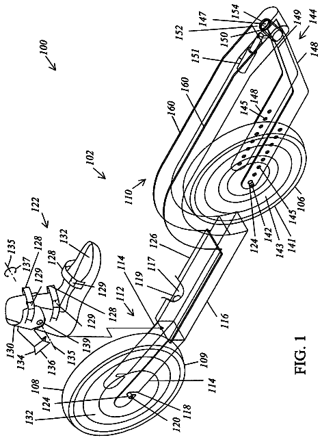
Sheet 1 of 4 from the published document. All sheets in the USPTO PDF
An exercise machine with a movable frame seat and pedal to change the level of the user's heart in relation to the pedal.
All 4 drawing sheets from the published document, cropped to the drawing.
What the patent claimed, word for word. All of it is now free to use.
Not Applicable.
Not Applicable.
A portion of the disclosure of this patent document contains material which is subject to intellectual property rights such as but not limited to copyright, trademark, and/or trade dress protection. The owner has no objection to the facsimile reproduction by anyone of the patent document or the patent disclosure as it appears in the Patent and Trademark Office patent files or records but otherwise reserves all rights whatsoever.
The present invention relates to improvements in exercise machines. More particularly, the invention relates to improvements particularly suited for pedal exercise machines to increase cardiovascular fitness. In particular, the present invention relates specifically to a height adjustable pedal machine that provides for positioning the pedals above the heart to increase fitness training performance. 2. Description of the Known Art
As will be appreciated by those skilled in the art, pedal exercise machines are known in various forms. Patents disclosing information relevant to pedal exercise machines include: U.S. Pat. No. 9,669,257 issued to Irving, et al. on Jun. 6, 2017 entitled Bicycling exercise apparatus; U.S. Pat. No. 9,630,049 issued to Hartman, et al. on Apr. 25, 2017 entitled Reciprocating rehabilitation device; U.S. Pat. No. 5,016,870 issued to Bulloch, et al. on May 21, 1991 entitled Exercise device; and U.S. Pat. No. 5,035,418 issued to Harabayashi on Jul. 30, 1991 entitled Cycle type athletic equipment. Each of these patents is hereby expressly incorporated by reference in their entirety.
From these prior references it may be seen that these prior art patents are very limited in their teaching and utilization, and an improved exercise machine is needed to overcome these limitations.
The present invention is directed to an improved adjustable heart height exercise machine using a base with an adjustable position for the user to change the relationship between the heart level and the foot pedal position or the knee position. In accordance with one exemplary embodiment of the present invention, an exercise machine is presented using a base and a pivoted top frame to adjust the user position. Another embodiment uses a simple base and ram to adjust the upper frame position. Finally, a simple base and vertical pole are used to adjust one end of the exercise machine to vary the heart level of the user in relation to the pedal position and the resultant knee position of the user. These and other objects and advantages of the present invention, along with features of novelty appurtenant thereto, will appear or become apparent by reviewing the following detailed description of the invention.
In the following drawings, which form a part of the specification and which are to be construed in conjunction therewith, and in which like reference numerals have been employed throughout wherever possible to indicate like parts in the various views:
FIG. 1 is a schematic view of an arc adjustment system.
FIG. 2 is a schematic view of an arc adjustment system showing a position adjustment of the seat and pedal to change the user orientation.
FIG. 3 is a schematic view of an arc adjustment system showing the user in a heart above foot pedal axis position.
FIG. 4 is a schematic view of an arc adjustment system showing the user in a heart level with knee pedal position.
FIG. 5 is a schematic view of an arc adjustment system showing the user in a heart below knee pedal position.
FIG. 6 is a schematic view of a ram lift system showing the user in a heart above foot pedal axis position.
FIG. 7 is a schematic view of a ram lift system showing the user in a heart level with knee pedal position.
FIG. 8 is a schematic view of a ram lift system showing the user in a heart below knee pedal position.
FIG. 9 is a schematic view of a vertical stand lift system showing the user in a heart above foot pedal axis position.
FIG. 10 is a schematic view of a vertical stand lift system showing the user in a heart level with knee pedal position.
FIG. 11 is a schematic view of a vertical stand lift system showing the user in a heart below knee pedal position.
FIG. 12 is a schematic view of a vertical stand lift system showing the user in a heart below knee pedal position.
As shown in FIG. 1 of the drawings, one exemplary embodiment of the present invention is generally shown as an adjustable heart height exercise machine 100 . FIGS. 1-12 show an adjustable heart height exercise machine 100 with FIGS. 3 through 12 showing a heart level 2 at various heights. FIGS. 3, 6, and 9 show a typical exercise position with the heart above knee pedal position 10 which coincides with a heart above foot pedal axis position 40 for these Figures. FIGS. 4, 7, and 10 show a heart level with knee pedal position 20 which coincides with a heart level with foot pedal axis position 50 . FIGS. 5, 8, 11, and 12 show a heart below knee pedal position 30 coinciding with a heart below foot pedal axis position 60 .
FIGS. 1 through 12 show various configurations of the adjustable heart height exercise machine 100 . FIGS. 1 through 5 show an arc adjustment system 200 . FIGS. 6 through 8 show a ram lift system 400 . FIGS. 9 through 12 show a vertical stand lift system 500 .
The arc adjustment system 200 includes a base frame 201 supported by a front foot 202 connected by a front leg 208 , mid foot 204 connected by a mid leg 210 , and back foot 206 directly connected to the base frame. The mid foot 204 is generally positioned wider than the front foot 202 and back foot 206 to give a stable platform for the arc adjustment system 200 . The base frame 201 includes capture rails 212 that hold roller wheels 214 to moveably support the moving arc frame 300 .
The moving arc frame 300 includes a frame body 302 with roller axles 304 to support the roller wheels 214 . The moving arc frame 300 also supports a foot pedal 306 attached by a pedal arm 308 to the rotational pedal base 310 mounted inside the pedal frame 312 . Note that foot pedal 306 can be a rotating pedal, an elliptical pedal, or even a pedal for a stair-stepper type mechanism Extending upwards from the moving arc frame 300 is the monitor frame 314 that supports a monitor 316 or other screen, paper, or other information or entertainment holder for use during exercise. The back of the moving arc frame 300 supports the seat frame 318 including a seat 320 , a back 322 , and a headrest 324 .
The ram lift system 400 differs in the use of a lift ram 402 that extend from a ram base point 404 to a ram arm point 410 using a ram body 406 and ram arm 408 .
The vertical stand lift system 500 differs in using a lift body 502 with a back wheel 504 and front arm 506 defining the user position. A height pin 508 is used with a stand pole 512 mounted on a stand plate 510 to change the angle. The stand pole 512 includes pin holes 514 for the height pin 508 .
Reference numerals used throughout the detailed description and the drawings correspond to the following elements: Heart level 2 Heart above knee pedal position 10 Heart level with knee pedal position 20 Heart below knee pedal position 30 Heart above foot pedal axis position 40 Heart level with foot pedal axis position 50 Heart below foot pedal axis position 60 Adjustable heart height exercise machine 100 Arc system 200 Base frame 201 Front foot 202 Mid foot 204 Back foot 206 Font leg 208 Mid leg 210 Capture rails 212 Roller wheels 214 Moving arc frame 300 Frame body 302 Roller axles 304 Foot pedal 306 Pedal arm 308 Pedal base 310 Pedal frame 312 Monitor frame 314 Monitor 316 Seat frame 318 Seat 320 Back 322 Headrest 324 Ram lift system 400 Lift ram 402 Ram base point 404 Ram body 406 Ram arm 408 Ram aim point 410 Vertical stand lift system 500 Lift body 502 Back wheel 504 Front arm 506 Height pin 508 Stand plate 510 Stand pole 512 Pin holes 514
From the foregoing, it will be seen that this invention well adapted to obtain all the ends and objects herein set forth, together with other advantages which are inherent to the structure. It will also be understood that certain features and subcombinations are of utility and may be employed without reference to other features and subcombinations. This is contemplated by and is within the scope of the claims. Many possible embodiments may be made of the invention without departing from the scope thereof. Therefore, it is to be understood that all matter herein set forth or shown in the accompanying drawings is to be interpreted as illustrative and not in a limiting sense.
When interpreting the claims of this application, method claims may be recognized by the explicit use of the word ‘method’ in the preamble of the claims and the use of the ‘ing’ tense of the active word. Method claims should not be interpreted to have particular steps in a particular order unless the claim element specifically refers to a previous element, a previous action, or the result of a previous action. Apparatus claims may be recognized by the use of the word ‘apparatus’ in the preamble of the claim and should not be interpreted to have ‘means plus function language’ unless the word ‘means’ is specifically used in the claim element. The words ‘defining,’ ‘having,’ or ‘including’ should be interpreted as open ended claim language that allows additional elements or structures. Finally, where the claims recite “a” or “a first” element of the equivalent thereof, such claims should be understood to include incorporation of one or more such elements, neither requiring nor excluding two or more such elements.
About 1,725 words. The USPTO PDF has it with every drawing.
Fees are due 3.5, 7.5 and 11.5 years after grant. This patent expired on December 14, 2025, so the fee marked "not paid" was the one that went unpaid.
Adjustable heart position pedal exercise machine
Filed Aug 2020 · granted Dec 2021Earlier publications, parents and continuations. None of them can still be enforced, or this patent would not be listed.
Prior art cited by the examiner or applicant. Useful when you check your own idea for novelty.
Everything on this page comes from the documents linked above.