Cross-reference to related application
This application claims priorities from Japanese Patent Application No. 2015-186560 filed on Sep. 24, 2015, the entire contents of which are incorporated herein by reference.
Field of invention
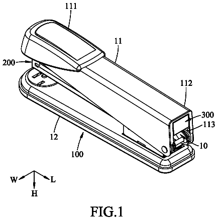
The present disclosure relates to a stapler capable of stapling a workpiece using non-metal staples.
Background art
In related art, there has been proposed a stapler capable of stapling a workpiece using staples made of a non-metal material which is a soft material, such as paper, instead of metal staples.
There has been proposed a stapler using staples made of such a non-metal soft material includes a pair of cutting blades for forming holes penetrating the workpiece and holding the staple, by which a pair of leg portions of the staple penetrate the workpiece when the one pair of cutting blades penetrate the workpiece.
In the stapler using the staple made of the non-metal soft material, an opening is formed on a workpiece placing base, and the cutting blade penetrating the workpiece and the leg portions of the staple held by cutting blade pass through the opening. Since the one pair of leg portions of the staple, which is inserted into the workpiece, are respectively bent to the inside and binds the workpiece, an opening is opened between parts through which the one pair of leg portions pass (for example, see Japanese Unexamined Patent Application Publication Nos. 2013-166206 and 2014-113679).
In the stapler according to the related art not being provided with a configuration in which the workpiece is supported on the opening of the paper placing base, the workpiece is deformed by a force to be applied to the workpiece along a moving direction of the cutting blade when the cutting blade penetrates the workpiece.
If the workpiece is deformed when the cutting blade penetrates the workpiece, a part of the workpiece coming in contact with the cutting blade is cut while being deformed according to the shape of the cutting blade. This causes the increase of a contact length between the workpiece and the cutting blade and the increase of a penetration load.
Summary of invention
One or more embodiments of the present disclosure provide a stapler capable of reducing a penetration load of the cutting blade for inserting leg portions of a staple into a workpiece.
According to an aspect of the present disclosure, a stapler is configured to bind a workpiece using a staple made of a non-metal soft material, the staple having a crown portion and a pair of leg portions formed by bending both longitudinal ends of the crown portion toward one direction. The stapler includes: a placing base on which the workpiece is placed; a penetrating part that includes a pair of cutting blades spaced apart from each other according to a length of the crown portion of the staple and causes the cutting blades to penetrate from one surface of the workpiece placed on the placing base to the other surface thereof an opening that is provided on the placing base so that the one pair of cutting blades and the one pair of leg portions of the staple inserted into the workpiece pass through the opening; and a pressing portion that is provided in the opening of the placing base and suppresses deformation of the workpiece caused by a force applied to the workpiece from the cutting blades when the cutting blades penetrate the workpiece.
In the stapler according to the present disclosure, when the cutting blades penetrate the workpiece, the pressing portion abuts against the other surface of the workpiece at the inside of parts through which the one pair of cutting blades penetrate and thus supports the workpiece which is pressed by a force applied from the cutting blades. Thus, when the cutting blades penetrate the workpiece, the deformation of the workpiece is suppressed by the pressing portion even when the force to be pressed along the moving direction of the cutting blades is applied to the workpiece.
For this reason, preferably, the pressing portion is configured such that a pressing surface thereof facing the other surface of the workpiece placed on the placing base is substantially on the same plane as a placing surface of the placing base.
Furthermore, preferably, the pressing portion protrudes to the opening of the placing base, provided in a cutting blade guide located inside the one pair of cutting blades penetrating the workpiece, and faces the workpiece placed on the placing base.
Furthermore, preferably, the stapler includes a bending part that is configured to bend the one pair of leg portions of the staple, which is inserted into the workpiece by the cutting blades, along the workpiece, and a guide driving part that is configured to retract the cutting blade guide and the pressing portion from the opening of the placing base when a bending operation of the one pair of leg portions of the staple is started in an operation of the bending part after a penetrating operation of the cutting blades with respect to the workpiece using a penetrating part.
According to the stapler of the present disclosure, the deformation of the workpiece is suppressed in the penetrating operation of the cutting blade with respect to the workpiece, and thus it is possible to suppress the increase in contact length of the cutting blade with the workpiece and the increase in penetration load when the cutting blade penetrates the workpiece while cutting it.
Brief description of drawings
FIG. 1 is a side sectional view illustrating one example of an internal configuration of a stapler according to one embodiment;
FIG. 2 is a side sectional view illustrating one example of the internal configuration of the stapler according to this embodiment;
FIG. 3 is a side sectional view illustrating one example of the stapler according to this embodiment;
FIG. 4 is a perspective view illustrating one example of the stapler according to one embodiment when seen from a front;
FIG. 5 is a perspective view illustrating one example of the stapler according to this embodiment when seen from a rear;
FIG. 6 is a forward sectional view illustrating one example of the internal configuration in a penetrating mechanism of the stapler according to this embodiment;
FIG. 7 is a forward sectional view illustrating one example of the internal configuration in a cutting/forming mechanism of the stapler according to this embodiment;
FIG. 8 is a plan view illustrating one example of a staple-materials-connecting-body;
FIG. 9 is a perspective view illustrating one example of a receiving state of the staple-materials-connecting-body;
FIG. 10 is a perspective view illustrating one example of a formed staple;
FIG. 11 is a cross-sectional view illustrating one example of a state in which paper sheets are stapled with the staple;
FIG. 12 is a perspective view illustrating one example of a staple cartridge;
FIG. 13 is a perspective view illustrating one example of the staple cartridge;
FIG. 14 is a perspective view illustrating one example of the internal configuration in a portion of the penetrating mechanism of the stapler according to this embodiment;
FIG. 15 is a front view illustrating one example of the penetrating mechanism;
FIG. 16 is a rear view illustrating one example of the penetrating mechanism;
FIG. 17 is a perspective view illustrating one example of the penetrating mechanism;
FIG. 18 is a perspective view illustrating one example of a cutting blade guide and a pressing portion;
FIG. 19 is a perspective view illustrating one example a cutting blade guide and a pressing portion;
FIG. 20 is a perspective view illustrating one example a cutting blade guide and a pressing portion;
FIG. 21 is a front view illustrating one example of the cutting blade guide and the pressing portion;
FIGS. 22A and 22B are plan views illustrating one example of the cutting blade guide and the pressing portion;
FIG. 23 is a side view illustrating one example of the cutting blade guide and the pressing portion;
FIG. 24 is an operation chart illustrating an exemplary operation of the penetrating mechanism;
FIG. 25 is an operation chart illustrating an exemplary operation of the penetrating mechanism;
FIG. 26 is an operation chart illustrating an exemplary operation of the penetrating mechanism;
FIG. 27 is an operation chart illustrating an exemplary operation of the penetrating mechanism;
FIG. 28 is an operation chart illustrating an exemplary operation of the penetrating mechanism;
FIG. 29 is an operation chart illustrating an exemplary operation of the penetrating mechanism;
FIG. 30 is an operation chart illustrating an exemplary operation of the penetrating mechanism;
FIG. 31 is an operation chart illustrating an exemplary operation of the penetrating mechanism;
FIG. 32 is an operation chart illustrating an exemplary operation of the penetrating mechanism;
FIGS. 33A and 33B are explanatory diagrams illustrating an example of operational effects according to this embodiment in a penetrating operation of the cutting blade with respect to paper sheets;
FIGS. 34A and 34B are explanatory diagrams illustrating existing problems in a penetrating operation of the cutting blade with respect to the paper sheets;
FIG. 35 is a graph illustrating a difference in penetration load due to the presence or absence of the pressing portion;
FIG. 36 is an operation chart illustrating an exemplary operation of the penetrating mechanism according to a difference in the number of paper sheets;
FIG. 37 is an operation chart illustrating an exemplary operation of the penetrating mechanism according to the difference in the number of paper sheets;
FIG. 38 is a front view illustrating one example of the cutting/forming mechanism;
FIG. 39 is a rear view illustrating one example of the cutting/forming mechanism;
FIG. 40 is a perspective view of the cutting/forming mechanism when seen from a front;
FIG. 41 is a perspective view of the cutting/forming mechanism when seen from a rear;
FIG. 42 is an operation chart illustrating an exemplary operation of the cutting/forming mechanism;
FIG. 43 is an operation chart illustrating an exemplary operation of the cutting/forming mechanism;
FIG. 44 is an operation chart illustrating an exemplary operation of the cutting/forming mechanism;
FIG. 45 is an operation chart illustrating an exemplary operation of the cutting/forming mechanism;
FIG. 46 is an operation chart illustrating an exemplary operation of the cutting/forming mechanism;
FIGS. 47A to 47C illustrate an operation of cutting the staple-materials-connecting-body;
FIGS. 48A to 48C illustrate an example of a bending mechanism;
FIGS. 49A and 49B are perspective views illustrating an example of the bending mechanism;
FIG. 50 is a side view illustrating one example of a driving force transmission mechanism of the bending mechanism;
FIGS. 51A to 51C illustrate an exemplary operation of the bending mechanism;
FIGS. 52A to 52C illustrate an exemplary operation of the bending mechanism;
FIGS. 53A to 53C illustrate an exemplary operation of the bending mechanism;
FIGS. 54A to 54C illustrate an exemplary operation of the bending mechanism;
FIGS. 55A to 55E illustrate an exemplary operation of the bending mechanism;
FIG. 56 is a side sectional view of the stapler illustrating one example of an attaching/detaching mechanism;
FIGS. 57A to 57C illustrate an exemplary operation of conveying the staple-materials-connecting-body by an operation of the attaching/detaching mechanism;
FIG. 58 is an operation chart illustrating an exemplary operation of an operating handle portion;
FIG. 59 is an operation chart illustrating an exemplary operation of the operating handle portion;
FIG. 60 is an operation chart illustrating an exemplary operation of the operating handle portion;
FIG. 61 is an operation chart illustrating an exemplary operation of the operating handle portion;
FIG. 62 is an operation chart illustrating an exemplary operation of the entire stapler;
FIG. 63 is an operation chart illustrating an exemplary operation of the entire stapler;
FIG. 64 is an operation chart illustrating an exemplary operation of the entire stapler;
FIG. 65 is an operation chart illustrating an exemplary operation of the entire stapler;
FIG. 66 is an operation chart illustrating an exemplary operation of the entire stapler;
FIG. 67 is an operation chart illustrating an exemplary operation of the entire stapler,
FIG. 68 is an operation chart illustrating an exemplary operation of the entire stapler;
FIG. 69 is an operation chart illustrating an exemplary operation of the entire stapler;
FIG. 70 is an operation chart illustrating an exemplary operation of the entire stapler;
FIG. 71 is an operation chart illustrating an exemplary operation of the entire stapler;
FIG. 72 is an operation chart illustrating an exemplary operation of the entire stapler;
FIG. 73 is an operation chart illustrating an exemplary operation of the entire stapler;
FIG. 74 is an operation chart illustrating an exemplary operation of the penetrating mechanism and a bending mechanism;
FIG. 75 is an operation chart illustrating an exemplary operation of the penetrating mechanism and the bending mechanism;
FIG. 76 is an operation chart illustrating an exemplary operation of the penetrating mechanism and the bending mechanism;
FIG. 77 is an operation chart illustrating an exemplary operation of the penetrating mechanism and the bending mechanism;
FIG. 78 is an operation chart illustrating an exemplary operation of the penetrating mechanism and the bending mechanism;
FIG. 79 is an operation chart illustrating an exemplary operation of the penetrating mechanism and the bending mechanism;
FIG. 80 is an operation chart illustrating an exemplary operation of the penetrating mechanism and the bending mechanism;
FIG. 81 is an operation chart illustrating an exemplary operation of the penetrating mechanism and the bending mechanism;
FIG. 82 is an operation chart illustrating an exemplary operation of the penetrating mechanism and the bending mechanism;
FIG. 83 is an operation chart illustrating an exemplary operation of the penetrating mechanism and the bending mechanism;
FIG. 84 is an operation chart illustrating an exemplary operation of the penetrating mechanism and the bending mechanism;
FIG. 85 is an operation chart illustrating an exemplary operation of the penetrating mechanism and the bending mechanism;
FIG. 86 is an operation chart illustrating an exemplary operation of the cutting/forming mechanism;
FIG. 87 is an operation chart illustrating an exemplary operation of the cutting/forming mechanism;
FIG. 88 is an operation chart illustrating an exemplary operation of the cutting/forming mechanism;
FIG. 89 is an operation chart illustrating an exemplary operation of the cutting/forming mechanism;
FIG. 90 is an operation chart illustrating an exemplary operation of the cutting/forming mechanism;
FIG. 91 is an operation chart illustrating an exemplary operation of the cutting/forming mechanism;
FIG. 92 is an operation chart illustrating an exemplary operation of the cutting/forming mechanism;
FIG. 93 is an operation chart illustrating an exemplary operation of the cutting/forming mechanism;
FIG. 94 is an operation chart illustrating an exemplary operation of the cutting/forming mechanism;
FIG. 95 is an operation chart illustrating an exemplary operation of the cutting/forming mechanism;
FIG. 96 is an operation chart illustrating an exemplary operation of the cutting/forming mechanism;
FIG. 97 is an operation chart illustrating an exemplary operation of the cutting/forming mechanism;
FIG. 98 is an operation chart illustrating an exemplary operation of the cutting blade guide;
FIG. 99 is an operation chart illustrating an exemplary operation of the cutting blade guide;
FIG. 100 is an operation chart illustrating an exemplary operation of the cutting blade guide;
FIG. 101 is an operation chart illustrating an exemplary operation of the cutting blade guide;
FIG. 102 is an operation chart illustrating an exemplary operation of the cutting blade guide;
FIG. 103 is an operation chart illustrating an exemplary operation of the cutting blade guide;
FIG. 104 is an operation chart illustrating an exemplary operation of the cutting blade guide;
FIG. 105 is an operation chart illustrating an exemplary operation of the cutting blade guide;
FIG. 106 is an operation chart illustrating an exemplary operation of the cutting blade guide;
FIG. 107 is an operation chart illustrating an exemplary operation of the cutting blade guide;
FIG. 108 is an operation chart illustrating an exemplary operation of the cutting blade guide;
FIG. 109 is an operation chart illustrating an exemplary operation of the cutting blade guide;
FIG. 110 is a front view illustrating main portions of a stapler according to a modified example of this embodiment;
FIG. 111 is a front view illustrating main portions of the stapler according to the modified example of this embodiment.
FIG. 112 is a perspective view illustrating an example of other configuration of the stapler according to the embodiment; and
FIG. 113 is a perspective view illustrating an example of other configuration of the stapler according to the embodiment.
Detailed description
An exemplary embodiment of a stapler according to the present disclosure will be described with reference to the accompanying drawings.
Exemplary Configuration of Stapler of the Embodiment
FIGS. 1 and 2 are side sectional views illustrating one example of an internal configuration of the stapler according to the embodiment, in which FIG. 1 shows a mounting state of a staple cartridge, and FIG. 2 shows a detached state of the staple cartridge. FIG. 3 is a side view illustrating one example of the stapler according to the embodiment.
FIG. 4 is a perspective view illustrating one example of the stapler according to one embodiment when seen from a front. FIG. 5 is a perspective view illustrating one example of the stapler according to this embodiment when seen from a rear. FIG. 6 is a forward sectional view illustrating one example of the internal configuration in a penetrating mechanism of the stapler according to this embodiment. FIG. 7 is a forward sectional view illustrating one example of the internal configuration in a cutting/forming mechanism of the stapler according to this embodiment.
First, explaining an outline of the stapler 1 according to this embodiment with reference to each drawing, the stapler 1 binds the paper sheets P which are a workpiece, using a staple 10 made of a non-metal material which is a soft material. The staple 10 is supplied as a band-like staple-materials-connecting-body 10 a integrally configured, as will be described later, and the staple-materials-connecting-body 10 a is received in a staple cartridge 11 , so that it is mounted in the stapler 1 .
The stapler 1 includes a penetrating mechanism 2 configured to make a hole in the paper sheets P and to penetrate the staple 10 into the paper sheets P by an action of ejecting the staple 10 , located at the leading end, which is cut from the staple-materials-connecting-body 10 a and formed.
Further, the stapler 1 includes a cutting/forming mechanism 3 configured to subsequently cut staples 10 from the staple-materials-connecting-body 10 a and form the subsequently cut staples 10 , in association with the operation of the penetrating mechanism 2 which ejects the staple 10 and penetrates the paper sheets P.
Further, the stapler 1 includes a paper holding mechanism 4 configured to hold the paper sheets P to be penetrated with the staple 10 by the penetrating mechanism 2 , in association with the operation of the penetrating mechanism 2 which ejects the staple 10 and penetrates the paper sheets P.
Further, the stapler 1 includes a bending mechanism 5 configured to bend the staple 10 penetrating the paper sheets P, in association with the operation of the penetrating mechanism 2 which ejects the staple 10 and penetrates the paper sheets P.
Further, the stapler 1 includes a transport mechanism 6 configured to convey the staples 10 cut subsequently from the staple-materials-connecting-body 10 a and formed to the penetrating mechanism 2 which ejects the staple 10 located at the leading end, and convey the staple-materials-connecting-body 10 a to the cutting/forming mechanism 3 from which the next staple 10 is conveyed to the penetrating mechanism 2 .
Further, the stapler 1 includes an attaching/detaching mechanism 7 A configured to convey the staple-materials-connecting-body 10 a received in the staple cartridge 11 to a desired position, in association with the transport mechanism 6 , when the staple cartridge 11 is mounted in the stapler 1 .
The stapler 1 includes a body 8 provided with the penetrating mechanism 2 , the cutting/forming mechanism 3 , the paper holding mechanism 4 , the bending mechanism 5 , the transport mechanism 6 , and the attaching/detaching mechanism 7 A which are described above. With the stapler 1 , the respective above-described constituent elements are operated by a desired driving force, and the respective constituent elements are operated in an interlocking manner by an operation of an operating handle 9 which is manipulated by a human power.
The body 8 includes a paper placing base 80 in which the paper sheets P are placed, and a cartridge receiving portion 81 mounted with the staple cartridge 11 . With the stapler 1 , the paper placing base 80 is installed at one side, that is, a front side, of the body 8 , and the cartridge receiving portion 81 is installed at a rear side.
In the body 8 , the penetrating mechanism 2 , the cutting/forming mechanism 3 , and the paper holding mechanism 4 are installed over the paper placing base 80 . The penetrating mechanism 2 , the cutting/forming mechanism 3 , and the paper holding mechanism 4 are disposed in order of the cutting/forming mechanism 3 , the penetrating mechanism 2 , and the paper holding mechanism 4 from the rear side in a conveyance direction of the staple-materials-connecting-body 10 a.
The body 8 is provided with guide grooves 82 a for guiding the movement of the penetrating mechanism 2 , guide grooves 82 b for guiding the movement of the cutting/forming mechanism 3 , and guide grooves 82 c for guiding movement of the paper holding mechanism 4 . The guide grooves 82 a to 82 c respectively extend in a vertical direction with respect to the paper sheets P placed on the paper placing base 80 , and are provided parallel to each other.
Further, in the body 8 , the transport mechanism 6 is installed at the rear of the penetrating mechanism 2 , the cutting/forming mechanism 3 , and the paper holding mechanism 4 . The body 8 is provided with a guide (not illustrated) for guiding movement of the transport mechanism 6 . In addition, in the body 8 , the bending mechanism 5 is installed under the paper placing base 80 .
The operating handle 9 is rotatably supported by a coupling shaft portion 20 b , which will be described later and serves as a fulcrum, of the penetrating mechanism 2 , when a cam groove 91 is guided along the shaft 90 installed in the body 8 . The operating handle 9 is installed in a vertically movable manner, with it being rotated around an virtual fulcrum defined by a track of the cam groove 91 guided by the shaft 90 and a track of the coupling shaft portion 20 b , and the rotation using the virtual fulcrum as a fulcrum axis is transmitted to the penetrating mechanism 2 . Further, the operating handle 9 includes a link 92 for transmitting the operation of the operating handle rotating around the virtual fulcrum to the transport mechanism 6 via the coupling shaft portion 20 b to be described later.
Since a distance between a power point, to which the power is applied, and the virtual fulcrum, and a distance between a point of the penetrating mechanism 2 , on which the power acts, and the virtual fulcrum are displaced depending on the shape of the cam groove 91 , the load applied to the operating handle 9 is varied.
The cam groove 91 is provided with a first guide groove portion 91 a which is guided by the shaft 90 at a timing at which the staple 10 starts to penetrate into the paper sheets P by the operation of the penetrating mechanism 2 , a second guide groove portion 91 b which is guided by the shaft 90 at a timing at which the staple 10 penetrates into the paper sheets P by the operation of the penetrating mechanism 2 , and a third guide groove portion 91 c which is guided by the shaft 90 at a timing at which the staple 10 is bent by the operation of the bending mechanism 5 .
In this embodiment, the shape of the cam groove 91 is set so that an operating load of the operating handle 9 , as an example of an operating member, becomes light at the timing at which the staple 10 starts to penetrate into the paper sheets P by the operation of the penetrating mechanism 2 , as an example of a penetrating part, and at the timing at which the staple 10 is bent by the operation of the bending mechanism 5 , as an example of a bending part.
In the stapler 1 , the operation of the operating handle 9 is transmitted to the penetrating mechanism 2 , the cutting/forming mechanism 3 , and the paper holding mechanism 4 , so that the penetrating mechanism 2 , the cutting/forming mechanism 3 , and the paper holding mechanism 4 are guided by the guide grooves 82 a to 82 c to move in the vertical direction with respect to the paper sheets P placed on the paper placing base 80 .
Accordingly, the stapler 1 performs the operation of the paper holding mechanism 4 to hold the paper sheets P placed on the paper placing base 80 , as the operating handle 9 is operated. Also, in association with the operation of the paper holding mechanism 4 to hold the paper sheets P, the stapler performs the operation of the penetrating mechanism 2 to allow the staple 10 , located at the leading end, which is cut from the staple-materials-connecting-body 10 a and formed to penetrate the paper sheets P. Furthermore, in association with the operation of the penetrating mechanism 2 to allow the staple 10 to penetrate the paper sheets P, the stapler performs the operation of the cutting/forming mechanism 3 to cut and form the next staple 10 from the staple-materials-connecting-body 10 a.
Further, the stapler 1 performs the operation of the bending mechanism 5 to bend the staple 10 penetrating the paper sheets P, in association with the operation of the operating handle 9 .
In the stapler 1 , the operation of the operating handle 9 is transmitted to the transport mechanism 6 via the link 92 , and thus the transport mechanism 6 is moved in a forward and backward direction along the conveyance direction of the staple-materials-connecting-body 10 a . Accordingly, as the operating handle 9 is operated, the stapler 1 conveys the staple-materials-connecting-body 10 a to the cutting/forming mechanism 3 by the transport mechanism 6 , and conveys the staple 10 located at the leading end, which is cut and formed from the staple-materials-connecting-body 10 a to the penetrating mechanism 2 .
Exemplary Configuration of Staple and Staple-Materials-Connecting-Body
FIG. 8 is a plan view illustrating one example of the staple-materials-connecting-body according to this embodiment. FIG. 9 is a perspective view illustrating one example of a receiving state of the staple-materials-connecting-body according to this embodiment. FIG. 10 is a perspective view illustrating one example of the formed staple according to the embodiment. FIG. 11 is a cross-sectional view illustrating one example of a state in which the paper sheets are stapled with the staple. Next, the configuration of the staple 10 and the staple-materials-connecting-body 10 a according to this embodiment will be described with reference to each drawing.
The staple 10 is made of a non-metal material, which is a soft material, having a predetermined thickness. The staple before being formed has an elongated straight shape, and both tip end portions 10 b in its longitudinal direction are tapered toward its tip end. In this embodiment, the staple 10 is made of the paper, but may be made of resin film or sheet, instead of the paper.
The staple-materials-connecting-body 10 a has a plurality of staples 10 arranged parallel to each other in the longitudinal direction, and each of the staples 10 is connected to each other by a pair of connecting portions 10 c provided in the inside of the tip end portions 10 b near both end portions thereof in the longitudinal direction. In the staple-materials-connecting-body 10 a , a portion outer than each connecting portion 10 c in the longitudinal direction of each staple 10 is not provided with a portion connecting the staples 10 arranged parallel to each other, due to the tapered shape of the tip end portion 10 b.
The staple-materials-connecting-body 10 a is provided with a hole 10 d adjacent to each connecting portion 10 c at the inside of the one pair of connecting portions 10 c connecting the staples 10 arranged parallel to each other. The hole 10 d has a predetermined length in the longitudinal direction and a short-side direction of the staples 10 , and, in this embodiment, the hole is formed by an aperture of a substantially rectangular shape with rounded corners. Also, the hole 10 d may be formed as a circular or oval aperture. The staple-materials-connecting-body 10 a is not provided with a cut portion of the staples 10 arranged parallel to each other between the connecting portion 10 c and the hole 10 d.
Further, the staple-materials-connecting-body 10 a is provided with a slit 10 e for separating the staples 10 arranged parallel to each other, between the respective holes 10 d . The slit 10 e is consecutively formed from one hole 10 d to the other hole 10 d , and thus the staple-materials-connecting-body 10 a is not provided with a connecting portion of the staple 10 arranged parallel to each other, between the hole 10 d and the slit 10 e.
The staple-materials-connecting-body 10 a is punched by pressing or stamping to have a predetermined shape of the tip end portions 10 b , the connecting portions 10 c , the holes 10 d , and the slits 10 e , which are described above.
The staple-materials-connecting-body 10 a is provided with an adhesive portion 10 f on one surface, that is, a reverse surface, of the one tip end portion 10 b which is the end portion of each of the staples 10 in the longitudinal direction. The adhesive portion 10 f uses a property to obtain a desired adhesive force when the respective leg portions 10 i of the staple 10 are bonded, in accordance with the material type of the staple 10 .
When the staple-materials-connecting-body 10 a is wound in a roll shape, as illustrated in FIG. 9 , the staples 10 are overlapped, and thus the adhesive portion 10 f located on the reverse surface of the one tip end portion 10 b of the outer-peripheral staple 10 comes into contact with the obverse surface of the one tip end portion 10 b of the inner-peripheral staple 10 .
When the staple-materials-connecting-body 10 a is wound in the roll shape, the other surface of the one tip end portion which at least comes into contact with the adhesive portion 10 f is provided with a coated portion 10 g made of silicon or the like, thereby preventing the staples 10 from sticking each other in the staple-materials-connecting-body 10 a which is wound.
Since the staple material 10 is cut and formed from the staple-materials-connecting-body 10 a by the cutting/forming mechanism 3 illustrated in FIGS. 1 and 7 , both end portions thereof in the longitudinal direction are bent by a predetermined length to be substantially parallel in a first direction that is an insertion/withdrawal direction of the cutting blade 21 into/from the paper sheets P, thereby the staple 10 in which a crown portion 10 h , as illustrated in FIG. 10 and leg portions 10 i at both end portions of the crown portion 10 h are formed.
According to the staple 10 cut and formed from the staple-materials-connecting-body 10 a , the one pair of leg portions 10 i penetrate the paper sheets P by the penetrating mechanism 2 , and the one pair of leg portions 10 i penetrating the paper sheets P are bent in a second direction along the paper sheets P by the bending mechanism 5 .
Since the reverse surface of the one tip end portion 10 b of the staple 10 is provided with an adhesive portion 10 f , the adhesive portion 10 f is provided on the reverse surface of one leg portion 10 i in the form of the crown portion 10 h and the leg portion 10 i which are formed. In this embodiment, the staple 10 has a bending position inside than the hole 10 d , and a length of the leg portion 10 i is equal to or more than a half of the length of the crown portion 10 h . If the one pair of leg portions 10 i are bent, the adhesive portion 10 f is overlapped with the leg portion 10 i.
Accordingly, as illustrated in FIG. 11 , after the other leg portion 10 i is bent in the second direction along the paper sheets P, the one leg portion 10 i is bent in the second direction along the paper sheets P, and thus the one leg portion 10 i is overlapped with the other leg portion 10 i , so that the leg portions 10 i are bonded at the adhesive portion 10 f.
Exemplary Configuration of Staple Cartridge
FIGS. 12 and 13 are perspective views illustrating one example of the staple cartridge. The configuration of the staple cartridge 11 will now be described with reference to each drawing. Herein, FIG. 12 shows the state in which the staple cartridge 11 is closed, while FIG. 13 shows the state in which the staple cartridge 11 is opened.
The staple cartridge 11 includes a cartridge body 12 and a cartridge cover 13 for covering the cartridge body 12 . In the staple cartridge 11 , the cartridge body 12 is closed by rotation of the cartridge cover 13 around a shaft 13 a provided at a rear end side thereof.
The cartridge body 12 has a staple receiving portion 12 a for receiving the staple-materials-connecting-body 10 a wound in the roll shape therein, and a staple conveying path 14 , protruding forward from the staple receiving portion 12 a , for conveying the staple-materials-connecting-body 10 a.
The staple conveying path 14 has a pair of guide convex portions 14 a adjacent to a tip end side thereof, the guide convex portions having a flat bottom portion along the surface of the staple-materials-connecting-body 10 a drawn from the staple receiving portion 12 a and extending in a straight line to suppress the staple-materials-connecting-body 10 a from lifting upward. Further, the staple conveying path 14 has a groove portion 14 b through which a feed claw (will be described later) of the transport mechanism 6 protrudes into the staple conveying path 14 .
The staple conveying path 14 is provided with a receiving table 16 for supporting a portion (corresponding to the crown portion 10 h ) of the staple 10 located at the leading end of the staple-materials-connecting-body 10 a conveyed through the staple conveying path 14 . The receiving table 16 is formed continuously from the staple conveying path 14 , and protrudes forward from the tip end of the staple conveying path 14 by conforming to a width corresponding to an inner width of the crown portion 10 h of the staple 10 and a length of one staple 10 in the short-side direction, thereby supporting the staple 10 to be cut and formed by the cutting/forming mechanism 3 .
The cartridge cover 13 is configured to cover the staple receiving portion 12 a and the staple conveying path 14 of the cartridge body 12 .
Accordingly, the front end position of the staple-materials-connecting-body 10 a can be determined by opening the cartridge cover 13 , accommodating the staple-materials-connecting-body 10 a wound in the roll shape into the staple receiving portion 12 a of the cartridge body 12 , and placing the front end portion of the staple-materials-connecting-body 10 a at a front end portion of the staple conveying path 14 .
As the cartridge cover 13 is closed, the front end position of the staple-materials-connecting-body 10 a is determined in such a way that the staple-materials-connecting-body 10 a can be conveyed, and then the staple-materials-connecting-body is received in the staple cartridge 11 .
The cartridge cover 13 is provided with a staple holding portion 17 at a position opposite to the receiving table 16 when the cartridge body 12 is closed. The staple holding portion 17 is made of a thin sheet-like metallic spring material in the example to push the staples 10 , located at the leading end which is conveyed to the receiving table 16 , in a direction of the receiving table 16 , thereby suppressing the displacement of the staple 10 when the staple 10 is cut and formed by the cutting/forming mechanism 3 . In the staple cartridge 11 , the cartridge cover 13 is provided with a lock portion 13 c for openably and closably locking the cartridge cover 13 , and the cartridge body 12 is provided with a pawl portion 12 b which is engaged with the lock portion 13 c.
If the staple cartridge 11 is mounted onto the cartridge receiving portion 81 of the stapler 1 , as illustrated in FIG. 1 , the staple conveying path 14 functions as a conveying path of the stapler 1 . Also, the receiving table 16 protrudes toward the cutting/forming mechanism 3 to function as a receiving table of the staple 10 cut and formed by the cutting/forming mechanism 3 .
Exemplary Configuration of Penetrating Mechanism
FIG. 14 is a perspective view illustrating one example of the internal configuration in a portion of the penetrating mechanism of the stapler according to this embodiment. FIG. 15 is a front view illustrating one example of the penetrating mechanism. FIG. 16 is a rear view illustrating one example of the penetrating mechanism. FIG. 17 is a perspective view illustrating one example of the penetrating mechanism. The configuration of the penetrating mechanism 2 will now be described with reference each drawing.
The penetrating mechanism 2 is one example of a penetrating part, and includes a penetrating mechanism body 20 transmitted with the operation of the operating handle 9 , two sheets of cutting blades 21 f or opening the holes in the paper sheets P by the operation of the penetrating mechanism body 20 and allowing the staple 10 to penetrate the paper sheets P, and a staple press-down portion 22 for pressing the staple 10 . The penetrating mechanism body 20 is operationally connected to the operating handle 9 to form an example of a connecting portion.
The penetrating mechanism body 20 has guide convex portions 20 a for guiding the movement of the penetrating mechanism 2 , a coupling shaft portion 20 b connected with the operating handle 9 , and a protruding pin 20 c for transmitting the operation of the operating handle 9 to the cutting/forming mechanism 3 . Also, the penetrating mechanism body 20 has a guide convex portion 20 d for guiding the movement of the penetrating mechanism 2 and the cutting/forming mechanism 3 , and a guide convex portion 20 e for guiding the movement of the penetrating mechanism 2 and the paper holding mechanism 4 .
The guide convex portions 20 a protrude outwardly from both ends of the penetrating mechanism body 20 in a widthwise direction, and are engaged with the guide grooves 82 a of the body 8 which are provided in both sides of the body 8 of the stapler 1 in the widthwise direction and are opened along the moving direction of the penetrating mechanism 2 . The guide convex portions 20 a are formed in an elliptical shape which is formed by connecting two semicircles with a straight line, to restrict a posture of the penetrating mechanism 2 in its rotating direction.
The coupling shaft portion 20 b is inserted into a hole 20 g provided in the penetrating mechanism body 20 , protrudes from both ends of the penetrating mechanism body 20 in the widthwise direction to the outside of the guide convex portions 20 a , and is engaged with the operating handle 9 .
The description continues in the full USPTO document.