 Lapsed, fee not paid5 drawings
Sports & Fitness · US 10,010,069 B2
Moving decoy carousel
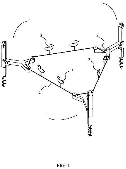
A motor-driven belt loops around posts staked in the ground or strapped to trees, carrying decoys in a circle to mimic flying birds.
US 10,010,738 B2 · Assignee: STAMINA PRODUCTS, INC. · Inventors: Gerschefske; Kevin et al.
Sheet 1 of 21 from the published document. All sheets in the USPTO PDF
An exerciser including a movable body carriage mounted on an exerciser frame for movement along tracks provided by the frame. A resilient foot engaging assembly extends from the exerciser frame. The resilient foot engaging assembly is adapted to be engaged by the user's feet to absorb the energy of movement in a first direction and to provide the user with a bouncing movement, which the user may translate into a movement of the movable body carriage in the opposite direction. The resilient foot engaging assembly may be provided as an attachment and retrofitted to existing exercisers. The resilient foot engaging assembly includes a unit mounting frame assembly and an independent usable exercising unit, such as an inflated dome or trampoline unit, removably secured thereon. The exerciser may include a resilient resistance system coupled to the movable body carriage and a set of pull lines with user grips trained over pulleys carried by the exerciser frame. Also disclosed are methods for enabling users to exercise in either one of two different modes.
Field of the Invention The present invention relates to methods of exercising and to exercise apparatuses with resilient foot supports for carrying out those methods. Description of Related Art One of the consistent challenges in the fitness industry is devising exercise methods and apparatuses that allow the user to achieve maximum, diverse fitness effects by performing exercises in comfortable positions. For example, a type or set of exercises may be particularly attractive and beneficial to the user if it provides strengthening, toning and cardiovascular benefits. Exercise equipment used to perform fitness exercises should ideally be relatively simple in construction, flexible in the types of exercises allowed, and adaptable to a wide range of resistances and levels of exertion. A popular type of exercise equipment provides a pair of generally parallel tracks, on which a carriage is m
8 of 21 drawing sheets so far from the published document, cropped to the drawing. Every sheet is in the USPTO PDF.
What the patent claimed, word for word. All of it is now free to use.
Field of the Invention
The present invention relates to methods of exercising and to exercise apparatuses with resilient foot supports for carrying out those methods.
Description of Related Art
One of the consistent challenges in the fitness industry is devising exercise methods and apparatuses that allow the user to achieve maximum, diverse fitness effects by performing exercises in comfortable positions. For example, a type or set of exercises may be particularly attractive and beneficial to the user if it provides strengthening, toning and cardiovascular benefits. Exercise equipment used to perform fitness exercises should ideally be relatively simple in construction, flexible in the types of exercises allowed, and adaptable to a wide range of resistances and levels of exertion.
A popular type of exercise equipment provides a pair of generally parallel tracks, on which a carriage is mounted for sliding or rolling movement along the tracks. Depending on the particular variation, the carriage may be connected to a resistance system including one or more resilient members, such as springs or bungee cords, which bias the carriage towards a particular position. The carriage may also be connected to pull lines that are trained over a pulley system, allowing the user to move the carriage by pulling the pull lines. The user exercises with such an apparatus by using the arms or legs to move the carriage along the tracks.
Sliding-carriage multi-function exercise equipment of this type also typically includes a foot rest or foot bar which extends in a direction generally perpendicular to the rails. The foot rest or foot bar is operationally fixed in position, and allows a user to control the movement of the carriage by exerting his or her leg muscles against it. A foot rest typically includes a set of frame members or frame portions that are adapted to connect to either the rails of the apparatus or other appropriate structures provided for that purpose. The frame members may also be attached to a rigid member, such as a board. The board is typically covered with a layer of foam or other cushioning material, which may be enclosed in a layer of outer material, such as vinyl. The foam and outer material cushion the user's feet to some degree and provide traction.
Rather than a board, the rigid member may comprise a generally U-shaped foot bar, which is typically a hollow bar that is adapted to be connected to the exercise apparatus at its ends. The top portion of the foot bar is covered with a traction/cushioning material. The user typically places his or her hands or feet on the cushioned portion of the foot bar to control the movement of the carriage.
One variation of the above-described type of exercise apparatus is disclosed in U.S. Pat. No. 5,967,955, which is incorporated herein by reference in its entirety. The disclosed apparatus includes a movable carriage mounted on generally parallel tracks and a foot rest of the type described above. The apparatus does not use resilient members to provide resistance; instead, resistive bias is provided by inclining the tracks at one of a number of angular orientations, thereby allowing the user to move the carriage by working against a corresponding fraction of his or her own weight bias under the influence of gravity using a pulley system that is coupled to the carriage. As the angular orientation of the carriage changes, the fraction of the user's weight bias changes correspondingly, such that at greater inclinations, the weight bias that the user works against is greater.
Another variation of the above-described type of exercise apparatus is that sold under the general name Pilates Performer™ (Stamina Products, Inc., Springfield, Mo., United States) for use with the Pilates exercise system. An apparatus of this type is shown in U.S. Pat. No. D382,319 to Gerschefske et al., the contents of which are incorporated by reference in their entirety. The apparatus includes a frame having a pair of generally parallel tracks that support a movable carriage which is mounted on the tracks with rollers for rolling horizontal movement along the tracks. A set of tensile resilient resistance elements is connected to the frame at one end and to the carriage at the other, thereby biasing the carriage towards a particular position. A pulley system and associated pull lines are coupled to the carriage, such that the carriage may be moved by application of force to the pull lines. A foot bar is provided at one end of the frame, and shoulder blocks are provided at one end of the carriage, allowing the user to position him or herself in a supine position to move the carriage against the resilient bias provided by the tensile resilient resistance elements using the muscles of either the legs or the arms.
One aspect of the invention relates to a method of enabling a person to exercise. The method comprises providing a movable body support for the exercising person which supports the exercising person in a position which allows the body of the exercising person to move with the movable body support while the feet of the exercising person are free to be moved with respect to the movable body support and providing a movable foot support separate from the body support in a position to be engaged by the feet of the exercising person supported on the movable body support. The method also comprises providing for the absorption of the energy of the movement of the movable body support in a first direction away from the movable foot support by the exercising person supported thereon and the conversion of the absorbed energy to a movement of the movable body support with the exercising person supported thereon in a second direction toward the movable foot support. Additionally, the method comprises providing for the controlled yielding of the movable foot support caused by the engagement thereof by the feet of the exercising person moving with the movable body support in the second direction and establishing as a result of the controlled yielding a bouncing movement by the movable foot support in the first direction, which the exercising person can translate into a movement of the movable body support in the first direction. The arrangement is such that the exercising person can control the repetition and magnitude of the movements of the movable body support by flexure of the legs at the knees.
Another aspect of the invention relates to an exerciser. The exerciser comprises a frame assembly, a movable body carriage supported by the frame assembly and constructed and arranged to support the body of an exercising person in a position which allows the body of the exercising person to move with the movable body carriage while enabling the feet of the exercising person to be moved with respect to the movable body carriage, and a resilient foot engaging assembly coupled with the frame assembly and constructed and arranged to be engaged by the feet of the exercising person supported on the movable body carriage, the movable body carriage being supported for movement in a first direction away from the resilient foot engaging assembly and a second direction toward the resilient foot engaging assembly, and the resilient foot engaging assembly being releasably fixed relative to the frame assembly and constructed and arranged to yield resiliently in response to the engagement of the feet of the exercising person moving with the movable body carriage in the second direction and to establish, as a result of the resilient yielding, a bouncing movement by the resilient foot engaging assembly in the first direction which can be translated by the exercising person into a movement of the movable body carriage in the first direction, the resilient foot engaging assembly being releasable from the fixed relation relative to said frame assembly and being constructed and arranged to independently function as a floor engaging exercising unit by itself.
A further aspect of the invention relates to an attachment for an exerciser of the type including a movable body support disposed on a frame assembly in a position to support the body of an exercising person in a position which allows the body of the exercising person to move with the movable body support while enabling the feet of the user to be free from the movable body support, a foot assembly adapted to be mounted on the frame assembly in a position to be engaged by the feet of the exercising person supported on said movable body support, and mounting structure disposed on the frame assembly, the mounting structure being constructed and arranged to detachably mount the foot assembly to the frame structure. The attachment comprises a movable foot support constructed and arranged to cooperate with the mounting structure to be mounted on the frame assembly in lieu of the foot assembly in a position to be engaged by the feet of a user supported on the movable body support. The movable foot support is constructed and arranged to yield resiliently in response to the engagement of the feet of the user supported on the movable body support therewith in a second direction toward the movable foot support and to establish, as a result of the resilient yielding, a bouncing movement by the movable foot support in a first direction which can be translated by the user into a movement in said first direction of said movable body support.
Another aspect of the invention relates to a dual mode exercising apparatus comprised of a resilient foot engaging unit including a unit frame having resilient foot engaging structure thereon, the unit frame being constructed and arranged to be supported on a horizontal floor surface in a first angled position so as to enable a user to perform exercise movements in which the user moves downwardly on the resilient foot engaging structure which bouncingly returns an upward movement to the user, and an exerciser constructed and arranged to have the resilient foot engaging unit removably attached thereto in an operative position wherein the unit frame is supported in a second angled position disposed at an angle to the horizontal, the exerciser including a body carriage movable in opposite directions under a resistance system for supporting a user thereon in such a way that the user can, during a movement of the body carriage in one direction, engage the resilient foot engaging structure with the user's feet and use the bouncingly return movement thereof to effect a movement of the body carriage in a direction opposite the first direction.
Another aspect of the invention relates to an exerciser comprised of a track, a movable body carriage mounted on the track to enable movement of the movable body support along the track in opposite directions, an elastically deformable foot engaging assembly arranged to be engaged by feet of an exercising person supported by the movable body carriage, the movable body carriage being movable in a first direction away from the elastically deformable foot engaging assembly and a second direction toward the elastically deformable foot engaging assembly, the elastically deformable foot engaging assembly being elastically deformable upon receipt of force applied by engagement of the feet of the exercising person, wherein the elastic deformation of the elastically deformable foot engagable applies a force against the feet of the exercising person to facilitate a movement of the movable body carriage in the first direction away from the elastically deformable foot engaging assembly, the elastically deformable foot engaging assembly including an inflated bladder.
Another aspect of the invention relates to an exercising apparatus comprised of a frame structure constructed and arranged to be supported on a horizontal surface, a foot engaging unit disposed on the frame structure, a movable body carriage mounted on the frame structure for movement toward and away from the foot engaging unit, and an electromechanical system between the frame structure and the movable body carriage for biasing the movable body carriage toward the foot engaging unit and for resisting movement of the movable body carriage away from the foot engaging unit, the electromechanical system including an electrical control circuit for electrically controlling the amount of bias and resistance provided by the electromechanical system.
Some improvements of the present invention are also based upon a dual concept. The first concept is that it can be beneficial to provide an attachment, which can be used both as the spring-biased attachment for the pilates-type exerciser and as an independently operable exerciser by itself. The second concept is that an inflatable dome-type exerciser can be used in practicing the first concept although the unit could be a small floor mounted trampoline or an inflatable exerciser ball as well. Examples of dome-type exercisers are disclosed in U.S. Pat. Nos. 6,702,726 and 6,422,983, the disclosures of which are hereby incorporated by reference into the present specification.
Accordingly, another aspect of the present invention is to provide a method of enabling a person to exercise in either one of two different modes comprising providing a resilient foot engaging unit and an exercising apparatus capable of selectively
coupling the resilient foot engaging unit with the exercising apparatus to provide the user with one mode of exercise and
releasing the resilient foot engaging unit from the exercising apparatus for use by itself to provide the exercising person with a different mode of exercise.
In one embodiment, the resilient foot engaging structure comprises an inflated dome-shaped bladder.
Still another aspect of the present invention is to provide an improvement wherein the pilates-type of exerciser has a resilient foot engaging assembly of an independent floor supported exercising function releasably secured thereto in place of the usual inverted U-shaped foot bar.
Another aspect of the present invention is the provision of an electromechanical, and, in one embodiment, an electromagnetic system for providing biased movement and resistance to movement for the movable body carriage of the exerciser.
Other aspects of the invention will become apparent from the following description.
The invention will be described with reference to the following drawings, in which like numerals represent like features throughout the figures, and in which:
FIG. 1 is a perspective view of an exerciser according to an embodiment of the present invention;
FIG. 2 is an exploded perspective view of the exerciser of FIG. 1 ;
FIG. 3 is a side elevational view of the exerciser of FIG. 1 ;
FIG. 4 is an elevational view of one end of the exerciser of FIG. 1 ;
FIG. 5 is an elevational view of the other end of the exerciser of FIG. 1 ;
FIGS. 6A-6C are side elevational views of the exerciser of FIG. 1 in various operative positions;
FIG. 7 is a perspective view illustrating an exerciser foot rest attachment according to the invention;
FIG. 8 is a perspective view of an exerciser according to another embodiment of the invention;
FIG. 9 is a side elevational view of the exerciser of FIG. 8 ;
FIG. 10 is a side elevational view of an exerciser according to yet another embodiment of the invention;
FIG. 11 is a top plan view of the foot support portion of the exerciser of FIG. 10 ; and
FIG. 12 is a top plan view of a foot support portion according to another embodiment of the invention, the exerciser itself being generally the same as that shown in FIG. 10 .
FIG. 13 is a perspective view of one embodiment of an exerciser constructed in accordance with the principles of the present invention;
FIG. 14 is a view similar to FIG. 13 showing the foot engaging assembly of the present invention in exploded perspective;
FIG. 15 is a fragmentary side elevational view of the foot end portion of the exerciser shown in FIG. 13 showing the foot engaging assembly in vertical section;
FIG. 16 is a side elevational view of the inflatable dome exercising unit forming a part of the foot engaging assembly;
FIG. 17 is a perspective view of the unit shown in FIG. 16 deployed for use as an independently functioning floor supported exerciser;
FIG. 18 is a perspective view of another embodiment of an exerciser constructed in accordance with the principles of the present invention;
FIG. 19 is a view similar to FIG. 18 showing the foot engaging assembly of the present invention in exploded perspective;
FIG. 20 is a fragmentary side elevational view of the foot end portion of the exerciser shown in FIG. 13 showing the foot engaging assembly in vertical section;
FIG. 21 is a side elevational view of the trampoline exercising unit forming a part of the foot engaging assembly; and
FIG. 22 is a perspective view of the unit shown in FIG. 16 deployed for use as an independently functioning floor supported exercising unit.
FIG. 23 is a view similar to FIG. 2 showing another carriage movement and return system, shown with a conventional inverted U-shaped foot engaging unit in lieu of the trampoline unit shown in FIG. 2 , with parts broken away for purposes of clearer illustration.
FIG. 1 is a perspective view of an exerciser, generally indicated at 10 , according to one embodiment of the invention. The exerciser 10 is generally of the type shown in U.S. Pat. No. Des. 382,319, which was incorporated by reference above. The exerciser 10 includes a frame assembly, generally indicated at 12 , a movable body carriage or support, generally indicated at 14 , disposed on the frame structure 12 in a position to support the body of the user in a position enabling the feet of the user to be free from the movable body support 14 , and a resiliently movable foot support, generally indicated at 16 , constructed and arranged to be mounted on the frame structure 12 in a position to be engaged by the feet of the user supported on the movable body support 14 .
The frame assembly 12 includes a frame 18 , which is adapted to support the movable body support 14 , the foot support 16 , and the user, as well as a stand 20 , which is adapted to connect to the frame 18 to hold the frame 18 in a generally horizontal plane above floor level. As is shown in FIG. 2 , an exploded perspective view of the exerciser 10 , the stand 20 comprises a plurality of legs 22 connected at respective upper ends thereof by cross bars 24 , such that the stand portion 20 is comprised of generally rectangular or trapezoidal segments having legs 22 disposed at the corners of the segments. End caps 26 of a rubber or other non-skid material may be provided at floor-contacting ends of the legs 22 . Upper receptacle sections 28 of the stand 20 are adapted to receive corresponding mating structures provided on the underside of the frame 18 (not shown in the Figures), so as to operatively secure the frame 18 to the stand 20 . The legs 22 of the stand 20 may be of any length that provides a convenient user height for the frame portion 18 .
Depending on the embodiment, the frame 18 and stand 20 may be separable, so that the exerciser 10 can be stored easily. Additionally, the stand 20 may be omitted or sold separately, particularly if the height provided by the stand 20 is not required for the exercises that are to be performed. Moreover, it may be desirable to construct the stand 20 such that one end is wider than the other. A stand 20 with one wider end and one narrower end may be desirable if one end of the exerciser 10 requires a broader base of support to prevent lateral tipping, or if the exerciser 10 is constructed such that the stand 20 will only mate with the frame 18 if the frame 18 is in a particular orientation.
In one embodiment, the frame 18 may be comprised of two generally parallel support tracks 30 , connected and braced by a number of cross members. Each of the support tracks 30 has a generally C-shaped cross-section, such that each support track 30 defines an interior track 32 , in the shape of a channel, which is adapted to receive engaging portions of the movable body support 14 . The engaging portions of the movable body support 14 in this embodiment are rollers 33 (shown in phantom in FIG. 3 ) that rollingly engage interior tracks 32 . The rollers 33 are mounted to the underside of the movable body support 14 on appropriately-sized bearings or projections, and allow the movable body support 14 to roll along the support tracks 30 between limiting portions of the support tracks 30 . The limiting portions of the support tracks 30 define the extent of travel for the movable body support 14 . In the exerciser 10 , one of the limiting portions is a crossbar 34 that extends between the two support tracks 30 ; the other limiting portion is defined by an endpiece 36 of the frame portion 18 . Alternatively, the limiting portions may simply be the ends of the grooves 32 in the support tracks 30 .
Although rollers 33 are used in the illustrated embodiment, a number of other types of bearings and other movement support structures are known in the art, and any one of these known types of bearings may be used in place of the rollers. For example, instead of rollers, blocks of low-friction material may be used, and the inside tracks 32 in the support tracks 30 may be lubricated in order to facilitate sliding movement with reduced friction.
The support tracks 30 , in one embodiment, may be continuous bars that run the length of the exerciser, or they may be comprised of sets of shorter bars which are secured together by welds or fasteners. As shown in FIG. 3 , each support track is comprised of two shorter support bars 38 , 40 . At one end, each shorter support bar 38 , 40 connects to an endpiece 36 , 37 to form an end of the frame 18 of the exerciser 10 . (The endpieces 36 , 37 of the illustrated embodiments are bars covered with decorative plastic moldings, but they may be made in other configurations.) At the other ends of the shorter support bars 38 , 40 , cooperating hinge structure 42 is provided, such that the shorter support bars 38 , 40 may be hingedly connected together in a manner which allows the exerciser 10 to be folded when not in use.
In alternative embodiments of the invention, the support tracks may have a substantially rectangular cross section, and a movable body support with rollers or other movement support structures may be configured so as to rest on top of the support tracks, rather than engaging inside tracks defined within them. The precise manner of engagement of the movable body support and the support tracks is not critical.
Several body-engaging components can be mounted on the movable body support 14 so as to facilitate the body positioning of the user. Two padded shoulder blocks 44 , one on each side of the body support 14 , extend vertically, and are positioned so as to engage the upper portion of the user's torso (i.e., at the collarbone or shoulder region) when the user is lying prone or supine on the movable body support 14 , so as to prevent the user from sliding relative to the movable body support 14 in a direction away from the foot support 16 . The shoulder blocks 44 may be removably attached to the movable body support 14 , for example, by a threaded connection.
A padded head rest 46 can also be mounted on the movable body support 14 . In the position illustrated in FIGS. 1 and 2 , the head rest 46 is positioned such that its user-contacting surface is generally horizontal and co-planar with those of the movable body support 14 . However, the head rest may be mounted on a multi-position bracket, such that its angular position may be adjusted relative to that of the movable body support so as to support the user's head in an inclined position. In addition to the head rest 46 , torso pad 48 is mounted on the movable body support 14 so as to cover a substantial portion of the movable body support 14 to provide traction and comfort.
When the user is lying on the movable body support 14 in either prone or supine position with his or her head on the head rest, the user's feet are free to move with respect to the movable body support 14 , and extend in a direction toward the resiliently movable foot support 16 . As can be seen in FIG. 1 and in the end elevational views of FIGS. 4-5 , in one embodiment, the foot support 16 comprises a generally rectangular peripheral frame member 50 that extends vertically, perpendicular to the orientation of the movable body support 14 . Resiliently attached to the peripheral frame member 50 is a flexible sheet member 52 . In the illustrated embodiment, the peripheral frame member 50 has a generally circular cross section, and a fabric flexible sheet member 52 is attached to the peripheral frame member 50 by a series of elastomeric, resilient, extensible cords 53 that are wrapped around the peripheral frame member 50 and pass through eyelets 54 provided along the edges of the fabric flexible sheet member 52 . The fabric flexible sheet member 52 may be nylon, canvas, or another suitable fabric capable of withstanding exercising use. The elastomeric, resilient, extensible cords 53 may comprise, for example, several strands of an elastomeric rubber encased in a fabric outer casing.
In addition to the arrangement shown in the figures and described above, the foot support 16 may be made in a variety of configurations and of a number of materials. For example, instead of being wrapped around the frame member, elastomeric cords or tension coil springs could be secured at first ends within the interior of a hollow peripheral frame member and could extend from it, being secured to the flexible sheet member at respective second ends. Alternatively, the flexible sheet member itself may be made of a resilient, elastomeric material, such as rubber, and may be secured to the frame member with adhesives or fasteners, without elastomeric cords. Moreover, the foot support could comprise an inflated resilient bladder supported by a peripheral frame or a rigid backing member, or it could comprise a board or other rigid member resiliently mounted on springs. In general, other embodiments of the invention would be designed to simulate the type of motion produced using the foot support 16 . Other embodiments of the foot support will be described in more detail below.
In one embodiment, the exerciser 10 may also carry a resilient resistance system coupled to the movable body support 14 . The crossbar 34 proximate to the footrest has several slots 60 formed in it. Each slot 60 in the crossbar is sized and adapted to accept one end of a tensile resilient resistance element 62 . A bracket on the underside of the movable body support 14 (not shown in the figures) includes a corresponding set of slots 60 , each slot 60 adapted to accept the other end of a tensile resilient resistance element 62 . In this embodiment, the crossbar 34 and bracket of the movable body support 14 each include four slots 60 ; however, the number of slots 60 may be selected arbitrarily, depending on the total desired resistance, the width of the crossbar 34 and bracket, and the total amount of space required for each resilient resistance element 62 . The exerciser 10 may be operated with any number of resilient resistance elements 62 installed in the slots.
The tensile resilient resistance elements 62 illustrated in FIGS. 1 and 2 are elastomeric cords with knobs 64 installed at the ends, so that the ends may be seated in the slots provided for them. The tensile resilient resistance elements 62 may also comprise tension coil springs, rubber bands, or similar structures. Depending on the type of resilient resistance elements 62 , hooks or other receiving structures may be used instead of slots. As those of skill in the art will appreciate, one of the functions of the tensile resilient resistance elements 62 is to bias the movable body support 14 to return to a position proximate to the movable foot support 16 when moved by the user away from the movable foot support 16 . However, particularly if the movable body support 14 is inclined and able to move under the influence of gravity, or if some other return mechanism is used, the resilient resistance system may be omitted.
The exerciser 10 of FIG. 1 also carries an arm exercise system. Two pull lines 56 are connected to the underside of the movable body support 14 . From the underside of the movable body support 14 , the pull lines 56 are trained over pulleys 58 that are carried by an upright bar 66 provided on the end of the exerciser opposite the foot support. The pulleys 58 are adapted to swivel, so as to allow the user to pull the pull lines 56 toward the foot support 16 in a variety of planes of motion. They pulleys 58 are also releasably mounted on the upright bar 66 by mounting structure 68 so that their angle and orientation can be changed by the user.
From the pulleys 58 , the pull lines 56 extend towards the foot support 16 , and are coupled to user grips 70 at their ends. Between the ends of the pull lines 56 and the user grips 70 , take-up fittings 72 are provided. Each take-up fitting has a number of holes 74 formed in it, such that if the pull lines are too long, they may be wrapped around and through the take-up fittings 72 to reduce their effective lengths. When the user grips the user grips 70 and causes the pull lines 58 to extend, he or she is working against the force bias provided by the tensile resilient resistance elements 62 . The arm exercise system, including the pull lines 56 , pulleys 58 and associated structures is an optional feature, and may not be included in some embodiments of the invention.
The foot support 16 is constructed and adapted to yield in a controlled manner in response to the engagement of the user's feet therewith in a direction toward the foot support 16 and to establish, as a result of the controlled yielding, a bouncing movement by the foot support 16 in the opposite direction, which can be translated by the user into a movement of the movable body support 14 in that opposite direction. In this context, the term “bouncing movement” may refer to movements during which the feet of the user lose contact with the foot support 16 , as well as resilient movements during which the feet of the user remain in contact with the foot support 16 . The term “feet” may refer to both of the user's feet together or to one individual foot; the exercises shown described here may be performed with one foot, each foot alternately, or both feet simultaneously. The terms “controlled yielding” and “resilient yielding” imply that the foot support 16 or individual foot portions thereof yield in such a manner that they are biased to return to their original position.
By the operation of the resilient resistance system, the movable body support 14 is constructed and arranged to absorb the energy of movement of the user on the movable body support in a direction away from the foot support 16 and to convert that absorbed energy into a movement toward the foot support 16 .
In one embodiment, the user may control the degree of resistive bias by changing the number of tensile resistive elements 62 that are connected between the crossbar 34 and the movable body support 14 . The pull lines 56 are constructed and arranged such that forces applied in a direction toward the foot support 16 by the user's arms are converted into movements of the movable body support 14 away from the foot support 16 . Alternatively, the user may control the position of the movable body support 14 solely by flexure of the legs against the foot support 16 .
One exemplary type of exercise that may be performed with the exerciser 10 is shown in FIGS. 6A-6C , although many types of exercises may be performed. As shown in FIG. 6A , the user P lies on the movable body support 14 in an essentially supine position, flexed at the knees, with the bottoms of his or her feet in contact with the flexible sheet member 52 of the foot support 16 . In FIG. 6A , the user P is also gripping the user grips 70 , and the pull lines 56 are extended forwardly. In the view of FIG. 6B , the user P has moved the movable body support 14 towards the foot support 16 , causing the flexible sheet member 52 to deflect. In the view of FIG. 6C , the resiliency of the elastomeric cords 62 attached to the flexible sheet member 52 has caused the flexible sheet member 52 to rebound, creating a bouncing movement by the foot support 16 that the user P can translate into a movement of the movable body support 14 . As shown in the FIG. 6C , the movable body support 14 has moved in a direction away from the foot support 16 . The degree of bouncing shown in FIG. 6C is for illustrative purposes. The actual amount of bouncing or resiliency will vary with the type of flexible sheet member 52 and elastomeric cords 62 that are used, as well as the way in which the user P controls the movement. The movements illustrated in FIGS. 6A-6C may be repeated any desired number of times at any desired frequency.
During the movements illustrated in FIGS. 6A-6C , the feet of the user P may or may not lose contact with the foot support 16 , depending on how the user P controls the movement. If the feet of the user P do lose contact with the foot support 16 during the bouncing movement, the separation distance may be at least partially controlled by the user P by exerting the muscles of the legs and/or abdomen appropriately when initially contacting the foot support 16 or thereafter.
The exerciser 10 may be used for a number of different types of exercise; the positions shown in FIGS. 6A-6C are merely exemplary. In particular, the user P may exercise using any combination of arm, leg, or arm and leg movements. If the user P uses both arm and leg movements during the exercise motions, as is shown in FIGS. 6A-6C , the effects of the arms and legs on the movement of the movable body support 14 are additive. The use of the foot support 16 may be particularly helpful in exercising the abdominal muscles, because the flexed-knee position of the user P will cause some of the exercising forces to be absorbed by and/or exerted by the abdominal muscles.
In addition to being installed on and included with an exercise machine like that shown in FIGS. 1-6 , in one embodiment, a foot support may also be sold and used as a separate attachment constructed and arranged to be installed or retrofitted on an exercise apparatus in lieu of a conventional foot bar or foot support. FIG. 7 illustrates a foot support 100 as it might be sold or used as an attachment. The foot support 100 includes connecting structures or portions 102 for connecting the foot support 100 with appropriate receptacles provided in the exercise apparatus. Depending on the configuration of the exerciser, the connecting structures 102 may simply be the terminal portions of the frame member 50 of the foot support. Alternatively, they could be keyed or shaped shafts, or could include some other structure adapted to cooperate with the receptacles of the exerciser to lock the foot support 100 into position within the exerciser. Additionally, a foot support attachment 100 may have any of the features described above with respect to the foot support 16 .
An exerciser 200 according to another embodiment is shown in the perspective view of FIG. 8 . The exerciser 200 may incorporate some or all of the structure and features described in U.S. Pat. No. 5,967,955, which was incorporated by reference above.
In general, the exerciser 200 includes a frame assembly, generally indicated at 202 , a movable body support, generally indicated at 204 , mounted on the frame assembly 202 for movement between limiting positions on the frame assembly 202 , and a resiliently movable foot support, generally indicated at 206 . The resiliently movable foot support 206 is essentially identical to the foot supports 16 , 100 described above, with the exception that it is particularly adapted to be inserted into an end crossmember 208 provided at the foot end of the frame structure 202 . Because the foot support 206 is essentially identical to the foot supports 16 , 100 described above, the description above will suffice to describe it.
In one embodiment, the exerciser 200 does not include a resilient resistance system; instead, as shown in the side elevational view of FIG. 9 , the frame assembly 202 includes two generally parallel support tracks 210 , which are supported on an inclined plane by a stand 212 . With this arrangement, the movable body support 204 is mounted for movement along the inclined plane defined by the tracks 210 . The tracks 210 of the exerciser 200 of this embodiment do not include interior tracks; instead, the movable body support 204 rests on top of the tracks 210 , and is supported by rollers 214 .
As supported by the stand 212 on the inclined plane, the movable body support 204 absorbs the energy of movement of a user supported thereon moving along the tracks 210 up the inclined plane because the user is working against the influence of gravity, and is thus storing potential energy. The movable body support 204 converts the absorbed energy into a movement along the tracks 210 down the inclined plane because the absorbed/stored potential energy is converted to kinetic energy.
In other words, the user is working against a portion of his or her own body weight, which provides the user with exercising resistance. The amount of exercising resistance may be varied by varying the incline of the tracks 210 . As shown, the stand 212 includes a connecting bracket 215 which may be supported at any one of a number of support points 216 . In the illustrated embodiment, the support points 216 are holes positioned at regular intervals along the height of the stand 212 . Each hole 216 is constructed and arranged to receive a pin inserted through a corresponding hole 217 in the connecting bracket. However, the support points 216 may be outwardly projecting members or any other type of structure capable of supporting the weight of the tracks 210 with the user positioned on them. In FIG. 9 , a second angular position of the tracks 210 is drawn in phantom. Despite the difference in resistive systems, the foot support 206 functions in essentially the same way as shown in FIGS. 6A-6C .
The movable body support 204 is also connected to pull lines 56 which are trained over pulleys 58 carried by the frame assembly 202 , such that the pull lines 56 may be pulled forwardly, towards the foot support 206 , which movement moves the movable body support 204 in a direction away from the foot support 206 . The ends of the pull lines 56 are provided with grips 70 . As with the exerciser 10 of the previous embodiment, the user may use any combination of arm, leg, or arm and leg movements to move the movable body support, and the effects of both arm and leg movements are additive.
It will be noted that in both the horizontal exerciser of FIGS. 1-6C and the inclined exerciser of FIGS. 8-9 , the main weight of the user is borne by the body support 14 , 204 . In its broadest aspect, the invention contemplates a vertical orientation of the body support 14 , 204 , in which case the body of the user P is supported on the body support 14 , 204 to move with the body support 14 , 204 without significant body weight support.
In the exercisers described above, the foot support 16 is a unitary structure that provides a single surface for contacting both of the user's feet. However, in other embodiments of the invention, individual foot supports, or individual contact areas, may be provided for each foot.
The description continues in the full USPTO document.
About 6,869 words. The USPTO PDF has it with every drawing.
Fees are due 3.5, 7.5 and 11.5 years after grant. This patent expired on July 3, 2026, so the fee marked "not paid" was the one that went unpaid.
Exercise apparatus with resilient foot support
Filed Feb 2007 · published Sep 2007Exercise apparatus with resilient foot support
Filed Feb 2007 · granted Oct 2010EXERCISE APPARATUS WITH RESILIENT FOOT SUPPORT
Filed Jul 2010 · published Nov 2010Exercise apparatus with resilient foot support
Filed Jul 2010 · granted Oct 2013EXERCISE APPARATUS WITH RESILIENT FOOT SUPPORT
Filed Sep 2013 · published Jan 2014Exercise apparatus with resilient foot support
Filed Sep 2013 · granted Jul 2018Earlier publications, parents and continuations. None of them can still be enforced, or this patent would not be listed.
Prior art cited by the examiner or applicant. Useful when you check your own idea for novelty.
Everything on this page comes from the documents linked above.


