 Expired, full term2 drawings
Biotech & Lab · US 6,779,674 B1
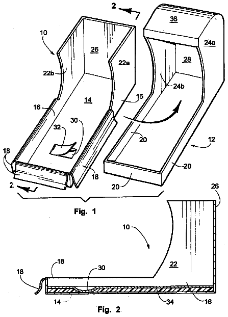
Disposable splash pan liner
A snug disposable liner for a laboratory splash pan, with a reservoir for polishing agents, so the pan needn't be disinfected after each use.
US 2019/0160466 A1 · Title as filed: ANALYSIS CELL, ANALYSIS DEVICE, ANALYSIS APPARATUS, AND ANALYSIS SYSTEM · Inventors: YAMAGATA; Yutaka et al.
Sheet 1 of 9 from the published document. All sheets in the USPTO PDF
A small analysis cell that tests a sample for a target with simple steps, sized for portable devices.
The present invention provides a tool that can analyze a target in a sample with simple operations and can be downsized, and an analysis method using the same. The analysis cell of the present invention includes: a main substrate: a sample inlet cover member; and a gas outlet cover member. The main substrate includes a flow path, an inlet for a sample, and a gas outlet, and the inlet and the gas outlet communicate with an outside. The inlet communicates with an upstream end portion of the flow path and the gas outlet communicates with a downstream end portion of the flow path. The flow path has a shape that expands from an upstream side toward a downstream side of the flow path. The sample inlet cover member is a liquid-tight member and can be fixed to the inlet when the sample inlet cover member is in use. The gas outlet cover member is a liquid-tight and gas-permeable member and can be fixed to the gas outlet when the gas outlet cover member is in use.
In recent years, for an infectious disease caused by viruses, bacteria, or the like, a common test method is to detect a target gene as an infection source in a biological sample. The target gene generally is detected by pretreating a collected sample, performing nucleic acid amplification of the target gene in the pretreated sample using primers, and detecting the presence or absence or amount of the nucleic acid amplification. Since the detection of the target gene requires a plurality of steps as described above and also requires a dedicated device and the like, the detection of the target gene is performed in a medical institution such as a hospital or a specialized testing institution. On the other hand, there are actual circumstances where detection at the individual level is required instead of the detection at the testing institution or the like, as described in the following. Fo
The first 3 of 9 drawing sheets from the published document, cropped to the drawing. Every sheet is in the USPTO PDF.
Independent claims and the claims that build on them, read from each claim's text.
What the application claimed, word for word. All of it is now free to use.
The present invention relates to an analysis cell, an analysis device, an analysis apparatus, and an analysis system.
In recent years, for an infectious disease caused by viruses, bacteria, or the like, a common test method is to detect a target gene as an infection source in a biological sample. The target gene generally is detected by pretreating a collected sample, performing nucleic acid amplification of the target gene in the pretreated sample using primers, and detecting the presence or absence or amount of the nucleic acid amplification. Since the detection of the target gene requires a plurality of steps as described above and also requires a dedicated device and the like, the detection of the target gene is performed in a medical institution such as a hospital or a specialized testing institution.
On the other hand, there are actual circumstances where detection at the individual level is required instead of the detection at the testing institution or the like, as described in the following. For example, if someone has symptoms of a cold, it is desirable from the viewpoint of preventing secondary infection to others if he/she can check whether he/she is infected with influenza viruses at home in advance. Among various infectious diseases, especially sexually transmitted diseases caused by HIV viruses and Candida are often discovered late because patients hesitate to be examined at hospitals. Accordingly, if these diseases can be tested at home, early detection of these diseases becomes possible.
In order to realize such a test at home, it is required that the test can be carried out with simple operations and that a small device is used for the test, and there have been attempts to develop devices for such point-of-care-testing (POCT). For example, a microtube-type device is disclosed as an analysis device that utilizes nucleic acid amplification (Patent Literature 1). This analysis device uses the so-called Eppendorf tube. A reaction is caused in the tube, the tube is irradiated with excitation light from above, and fluorescence in the tube is measured also from above. However, when the Eppendorf tube is used, it is necessary to use a heat block, and therefore, the analysis device is large in size. CITATION LIST Patent Literature
However, since a pretreatment of a sample, mixing of the sample with a nucleic acid amplification reagent, a nucleic acid amplification reaction, and detection of the reaction all need to be performed, a compact device that can be used at an individual level with simple operations has not yet been provided. SUMMARY OF INVENTION Technical Problem
With the foregoing in mind, it is an object of the present invention to provide, for example, a tool that can analyze a target in a sample with simple operations and can be downsized, and an analysis method using the same. Solution to Problem
In order to achieve the above object, the present invention provides an analysis cell including: a main substrate; a sample inlet cover member; and a gas outlet cover member, wherein the main substrate includes a flow path, an inlet for a sample, and a gas outlet, and the inlet and the gas outlet communicate with an outside, the inlet communicates with an upstream end portion of the flow path and the gas outlet communicates with a downstream end portion of the flow path, the flow path has a shape that expands from an upstream side toward a downstream side of the flow path, the sample inlet cover member is a liquid-tight member and can be fixed to the inlet when the sample inlet cover member is in use, and the gas outlet cover member is a liquid-tight and gas-permeable member and can be fixed to the gas outlet when the gas outlet cover member is in use.
The present invention also provides an analysis device for the analysis cell according to the present invention, including: an insertion section to which the analysis cell is to be inserted; a heating section configured to heat the analysis cell; a light source configured to irradiate the analysis cell with light; a photodetection section configured to detect light from the analysis cell; and a signal conversion section for converting the detected light to a signal.
The present invention also provides an analysis apparatus including: the analysis cell according to the present invention; and the analysis device according to the present invention.
The present invention also provides an analysis kit including the analysis device according to the present invention and the analysis cell according to the present invention.
The present invention also provides an analysis method including: an analysis unit; a storage unit; and a display unit, wherein the analysis unit is the analysis apparatus according to the present invention for analyzing a sample, the storage unit is a unit configured to store an analysis result obtained by the analysis unit, and the display unit is a unit configured to display the analytical result. Advantageous Effects of Invention
The present invention allows downsizing of an analysis cell, an analysis device, and the like, and also allows a target in a sample to be analyzed with simple manipulations, for example.
FIGS. 1A to 1C schematically show an example of the analysis cell of the present invention. FIG. 1A is a top view, FIG. 1B is a sectional view viewed in the arrow direction of line I-I in FIG. 1A , and FIG. 1C is a sectional view viewed in the arrow direction of line II-II in FIG. 1A .
FIGS. 2A and 2B are top views showing variations of the gas outlet in the analysis cell of the present invention.
FIG. 3 is a schematic view showing an expanding angle of the flow path in the analysis cell of the present invention.
FIGS. 4A to 4D are schematic views illustrating a method of using the analysis cell of the present invention.
FIGS. 5A and 5B are sectional views showing an example of the reagent section in the analysis cell of the present invention.
FIGS. 6A and 6B are sectional views showing another example of the reagent section in the analysis cell of the present invention.
FIG. 7 is a sectional view showing an example of the analysis cell of the present invention.
FIG. 8 is a sectional view showing another example of the analysis cell of the present invention.
FIGS. 9A to 9C are sectional views showing still another example of the analysis cell of the present invention.
FIGS. 10A and 10B are top views showing variations of the gas outlet in the analysis cell of the present invention.
FIG. 11 is a sectional view schematically showing an example of a method of using the analysis device of the present invention and the analysis cell of the present invention.
FIG. 12 is a schematic view showing an example of a display screen in the analysis system of the present invention.
FIG. 13 shows photographs of a flow path of a cell in Example 1 of the present invention.
FIG. 14 shows photographs of a flow path of a cell in Example 2 of the present invention.
In the analysis cell of the present invention, for example, the main substrate has at least two gas outlets, and the two gas outlets are disposed in a direction perpendicular to a flow path direction.
In the analysis cell of the present invention, for example, the sample inlet cover member is a sealing member and is fixed to the inlet after the sample is injected into the analysis cell
In the analysis cell of the present invention, for example, the sample inlet cover member is a cap member and is attachable and detachable with respect to the inlet.
In the analysis cell of the present invention, for example, the main substrate has a tubular portion that protrudes upward on an upper surface of the main substrate, and an opening of the tubular portion is the inlet.
In the analysis cell of the present invention, for example, the sample inlet cover member is a cap member and can be fitted to the protruding portion.
In the analysis cell of the present invention, for example, the flow path has a reagent section and a reagent is disposed in the reagent section.
In the analysis cell of the present invention, for example, a heat-fusible film containing the reagent is disposed on the reagent section.
In the analysis cell of the present invention, for example, the heat-fusible film is at least one selected from the group consisting of agarose films, agar films, carrageenan films, and gelatin films.
In the analysis cell of the present invention, for example, a dry composition containing the reagent and a poorly water-soluble substance is disposed in the reagent section.
The analysis cell of the present invention is configured such that, for example, it further includes an attachable and detachable antifouling member, and the antifouling member is disposed behind the gas outlet cover member in a flow direction.
In the analysis cell of the present invention, for example, the main substrate further includes a gas release bypass, and one end of the gas release bypass communicates with the inlet and the other end of the gas release bypass communicates with the gas outlet via the gas outlet cover member.
In the analysis cell of the present invention, for example, a cross-sectional shape of the flow path in a direction perpendicular to the flow direction of the flow path is at least one selected from the group consisting of polygonal shapes, circular shapes, elliptical shapes, and semicircular shapes.
In the analysis cell of the present invention, for example, the main substrate is in a rectangular parallelepiped shape, among outer surfaces of the main substrate, any one outer surface that is parallel to the flow direction of the flow path is a heated surface to be heated, among the outer surfaces of the main substrate, at least one of the outer surfaces other than the heated surface is an irradiated surface to be irradiated with light, and among the outer surfaces of the main substrate, at least one of the outer surfaces other than the heated surface is an extraction surface from which light generated in the flow path is extracted.
In the analysis cell of the present invention, for example, on at least one surface of the main substrate, a region corresponding to the flow path is formed of a member that transmits excitation light.
In the analysis cell, for example, in the main substrate, a portion on a downstream side from a downstream end portion of the flow path is formed of a member that transmits fluorescence.
In the analysis cell of the present invention, for example, the main substrate is formed of a member that transmits light.
In the analysis cell of the present invention, for example, the member that transmits light is a transparent member.
In the analysis cell of the present invention, for example, the reagent is a nucleic acid amplification reagent.
In the analysis device of the present invention, for example, the insertion section is configured such that an insertion direction of the analysis cell is parallel to a direction in which the flow path of the analysis cell extends, among side surfaces of the insertion section, the heating section is disposed on an inside or an outside of any one side surface that is parallel to the insertion direction of the analysis cell, among the side surfaces of the insertion section, the light source is disposed on an inside of at least one of the side surfaces other than the side surface on which the heating section is disposed, and among the side surfaces of the insertion section, the photodetection section is disposed on an inside of at least one of the side surfaces other than the side surface on which the heating section is disposed and the side surface on which the light source is disposed.
In the analysis device of the present invention, for example, the photodetection section has a fluorescence filter, a lens, and a photodetector, and the fluorescence filter, the lens, and the photodetector are disposed in this order from a side closer to the side surface of the insertion section.
In the analysis device of the present invention, for example, a thermally conductive plate is disposed between the insertion section and the heating section.
The analysis device of the present invention further includes a terminal, for example.
The analysis device of the present invention is configured such that, for example, it further includes a storage unit, and the storage unit is configured to store signal data converted by the signal conversion section.
In the analysis device of the present invention, for example, the light source is a surface irradiation type light source.
In the analysis device of the present invention, for example, the light source is a light emitting diode (LED).
The analysis device of the present invention is configured such that, for example, the analysis system includes a terminal apparatus and a server, the terminal apparatus includes the analysis unit, the server includes the storage unit and the display unit, and the terminal apparatus and the server can be connected to each other via a communication line network.
The analysis device of the present invention is configured such that, for example, the analysis system includes a terminal apparatus and a server, the terminal apparatus includes the analysis unit, the analysis unit further includes a terminal, the server includes the storage unit and the display unit, and the terminal apparatus can be connected to the server via the terminal of the terminal apparatus.
In the analysis system of the present invention, for example, the terminal is an external connection terminal.
Hereinafter, the present invention will be described more specifically with reference to illustrative examples. It is to be noted, however, that the present invention is not limited by the following descriptions.
The present invention relates to an analysis cell, an analysis device, an analysis apparatus, and an analysis system. According to the present invention, analysis of a sample can be carried out by, for example, mixing the sample with a reagent to prepare a reaction system using the analysis cell of the present invention and then setting the reaction system in the analysis device of the present invention, thereby constituting the analysis apparatus and the analysis system of the present invention.
[Analysis Cell]
The analysis cell of the present invention is, as described above, an analysis cell including: a main substrate; a sample inlet cover member; and a gas outlet cover member, wherein the main substrate includes a flow path, an inlet for a sample, and a gas outlet, and the inlet and the gas outlet communicate with an outside, the inlet communicates with an upstream end portion of the flow path and the gas outlet communicates with a downstream end portion of the flow path, the flow path has a shape that expands from an upstream side toward a downstream side of the flow path, the sample inlet cover member is a liquid-tight member and can be fixed to the inlet when the sample inlet cover member is in use, and the gas outlet cover member is a liquid-tight and gas-permeable member and can be fixed to the gas outlet when the gas outlet cover member is in use.
The analysis cell of the present invention can analyze a sample by, for example, inserting the analysis cell into the analysis device of the present invention to be described below.
The term “flow direction” as used in the present invention is a direction in which a sample supplied to the flow path flows, and for example, the inlet side is an upstream side and the gas outlet side is a downstream side. The term “vertical direction” as used in the present invention is a direction that extends vertically when the analysis cell of the present invention is used, and for example, in the state where the analysis cell is placed on a table, the side facing the table is a downward direction, and the opposite side is an upward direction. The term “width direction” as used in the present invention is, for example, a direction perpendicular to both the flow direction and the vertical direction.
Main Substrate
As described above, the main substrate includes the flow path, the inlet, and the gas outlet, the inlet communicates with the upstream end portion of the flow path, and the gas outlet communicates with the downstream end portion of the flow path.
The main substrate may be composed of one substrate or two or more substrates, for example. In the latter case, the main substrate includes, for example, an upper substrate and a lower substrate, and the main substrate is a laminate of the upper substrate and the lower substrate.
The overall shape of the main substrate is not particularly limited. The main shape of the entire main substrate is, for example, a rectangular parallelepiped shape or a flat plate shape, and for example, among the length, the width, and the thickness thereof, the thickness in the vertical direction has the shortest length. The size of the main substrate is not particularly limited.
The material of the main substrate is not particularly limited, and may be a resin, glass, or the like. The resin preferably is a light-transmitting resin to be described below, for example.
Flow Path
In the main substrate, the flow path is formed inside the main substrate, for example, and specifically, the flow path preferably is a hollow region formed inside the main substrate. When the main substrate includes the upper substrate and the lower substrate, the flow path is formed by, for example, overlaying the upper substrate with the lower substrate in such a manner that they face each other. As a specific example, in the case where the upper substrate has a recess on a surface thereof facing the lower substrate, when the upper substrate is overlaid on the lower substrate, a space is formed by the recess formed on the upper substrate and the lower substrate covering the recess, and this space serves as the flow path. In the case where the lower substrate has a recess on the surface thereof facing the upper substrate, when the upper substrate is overlaid on the lower substrate, a space is formed by the recess formed on the lower substrate and the upper substrate covering the recess, and this space serves as the flow path. Furthermore, in the case where the upper substrate and the lower substrate both have recesses on surfaces thereof facing each other, when the upper substrate is overlaid on the lower substrate, a space is formed by the recesses formed on both the substrates, and this space serves as the flow path.
As described above, the flow path has a shape that expands from the upstream side toward the downstream side (also referred to as “expanding shape” hereinafter). It is preferable that the expanding shape is such that, for example, the flow path expands in the width direction from the upstream side toward the downstream side. For example, the flow path may have the above-described expanding shape over the entire length from the upstream side to the downstream side or may have the above-described expanding shape in a part thereof. Specific examples of the flow path having the expanding shape include a flow path having a tapered shape and a flow path having a tear drop shape.
It is preferable that the expanding shape of the flow path satisfies, for example, the expression 1<(b/a), where “a” is the cross-sectional area of the upstream end portion of the flow path and “b” is the cross-sectional area of the downstream end portion of the flow path.
In the flow path, the expanding angle of the expanding shape is not particularly limited. The expanding angle can be expressed as, for example, an angle at which the downstream end portion expands in the width direction relative to the upstream end portion in the expanding shape of the flow path. FIG. 3 schematically shows the flow path and the expanding angle. In FIG. 3 , the interior of the expanding shape is the flow path, R is the upstream end portion of the flow path, and α is the expanding angle. The expanding angle (α) is 0.01° to 60°, for example.
The cross-sectional shape of the flow path is not particularly limited. The cross section of the flow path is a cross section taken in a direction perpendicular to the flow direction of the flow path, and specifically is a cross section of a void space inside the flow path. The cross-sectional shape of the flow path may be, for example, a polygonal shape, a circular shape, or the like. The polygonal shape is, for example, a quadrangular shape, a triangular shape, an inverted triangular shape, or the like, the quadrangular shape is, for example, a square shape, a rectangular shape, a diamond shape, or the like, and the circular shape is, for example, a perfectly circular shape, an elliptical shape, a semicircular shape, or the like (the same applies hereinafter).
The inner wall of the flow path may have, for example, a flat surface, a smooth surface, or a rough surface. When the inner wall has a rough surface, the rough surface may have grooves or may have a pleated shape, for example.
In the analysis cell of the present invention, for example, it is possible to control a capillary phenomenon at a time when a sample is flowing through the flow path by the cross-sectional shape of the flow path. With this configuration, for example, it is possible to set the analysis cell of the present invention such that the same capillary phenomenon occurs throughout the entire flow path or a different capillary phenomenon occurs only at any desired region in the flow path. Accordingly, for example, when the sample is introduced to the analysis cell, it is also possible to control diffusion of a reagent in the reagent section in the flow path and the order of dissolving reagents. The capillary phenomenon may be controlled by, for example, forming both lower edges of the flow path into angular shapes or curved shapes (bent shapes), or when the flow path has a polygonal cross-section, the capillary phenomenon may be controlled by adjusting the angle of the lower edges of the flow path. When the flow path has a circular cross-section, the capillary phenomenon may be controlled by adjusting the curvature of the curved surface, for example.
In the main substrate, the number of the flow paths is not particularly limited, and the main substrate may have one flow path or two or more flow paths, for example. From the viewpoint of downsizing of the analysis cell, it is preferable that the main substrate has one flow path.
It is preferable that the width of the upstream end portion of the flow path is substantially the same as the width of the inlet, for example.
The size of the flow path is not particularly limited. It is preferable that the cross-sectional area of the hollow space of the flow path is substantially the same as the cross-sectional area of the inlet, for example. The cross-sectional area of the flow path is such that, for example, the lower limit thereof is 0.001 mm.sup.2 or more, the upper limit thereof is 500 mm.sup.2 or less, and the range thereof is from 0.001 mm.sup.2 to 500 mm.sup.2. When the flow path is in a rectangular parallelepiped shape, the width of the flow path is such that, for example, the lower limit thereof is 0.05 mm or more, the upper limit thereof is 50 mm or less, and the range thereof is from 0.05 mm to 50 mm, and the depth of the flow path is such that, for example, the lower limit thereof is 0.02 mm or more, the upper limit thereof is 10 mm or less, and the range thereof is from 0.02 mm to 10 mm.
The length of the flow path in the flow direction is such that, for example, the lower limit thereof is 1 mm or more, the upper limit thereof is 100 mm or less, and the range thereof 1 mm to 100 mm. The length of the upstream end portion in the width direction (the narrowest width) is such that, for example, the lower limit thereof is 0.05 mm or more, the upper limit thereof is 10 mm or less, and the range thereof is from 0.05 to 10 mm. The length of the downstream end portion in the width direction (the widest width) is such that, for example, the lower limit thereof is 0.05 mm or more, the upper limit thereof is 50 mm or less, and the range thereof is from 0.05 to 50 mm. The length in the vertical direction (depth) is such that, for example, the lower limit thereof is 0.02 mm or more, the upper limit thereof is 10 mm or less, and the range thereof is from 0.02 to 10 mm.
The material of the main substrate is not particularly limited. For example, in the case where the main substrate is set in an analysis device to be described below to perform optical detection, it is preferable that an irradiation region to be irradiated with light and an extraction region from which light generated by a reaction in the flow path is to be extracted are formed of light-transmitting members. Also, it is preferable that the entire main substrate is formed of a light-transmitting member, because, for example, the irradiating region and the extracting region can be set as appropriate according to the configuration of the analysis device.
The light-transmitting member is, for example, a member that does not absorb light such as excitation light and fluorescence to be detected. The member is, for example, a transparent member, and examples of the transparent member include those formed of ultraviolet-transmitting polymers such as acrylic resins, polycarbonate, polymethylpentene, and cycloolefin polymers.
Reagent Section
In the analysis cell of the present invention, for example, a reagent section having a reagent disposed therein in advance may be provided in the flow path or a sample mixed with the reagent may be injected into the flow path when the analysis cell is used. In the former case, the flow path has the reagent section in a region between the upstream end portion and the downstream end portion of the flow path, for example.
When the flow path has the reagent section, the number of reagent sections is not particularly limited. For example, the flow path may have one reagent section or two or more reagent sections. In the latter case, for example, a plurality of reagents used for analysis may be disposed in the flow path as separate reagent sections. Regarding the plurality of reagents, for example, when the order of adding the reagents to the sample is set or when the reagents should not be in contact with each other until they are mixed with the sample, it is preferable that the respective reagents are disposed as separate reagent sections in the flow path. When the order of adding the plurality of reagents to the sample is set, it is preferable that the reagent sections of the respective reagents are disposed from the upstream end portion to the downstream end portion of the flow path in accordance with the order of adding the reagents, for example.
The reagent section is preferably immobilized on the flow path. The reagent section may be disposed on any of a bottom surface, an upper surface, side surfaces, and the like of the flow path, for example.
The configuration of the reagent section is not particularly limited as long as a reagent used for analysis is disposed in any desired region in the flow path directly or indirectly. It is preferable that the reagent is immobilized on the flow path, for example. Specifically, it is preferable that the reagent is immobilized on the flow path until it comes into contact with the sample and that the reagent is separated from the flow path upon contact with the sample introduced to the flow path.
Examples of the form of the reagent section include a first form in which a dry composition containing the reagent is disposed. According to this reagent section, for example, when a liquid sample comes into contact with the reagent, the reagent is dissolved in the sample. The dry composition may contain, for example, a poorly water-soluble substance in addition to the reagent. The poorly water-soluble substance is, for example, a sustained-release substance that diffuses into a liquid sample. Specific examples of the poorly water-soluble substance include hydrophilic polymers such as starch, gelatin, bovine serum albumin, cellulose, cellulose derivatives, polyacrylic acid, polyethylene oxide, polyethylene glycol, polyvinyl alcohol, and polyvinyl pyrrolidone. The liquid composition may further contain, for example, as enzyme stabilizing agents, a protecting agent such as an amino acid, a salt, or a surfactant and a sugar such as sucrose, lactose, or trehalose.
Such a reagent section can be formed by, for example, supplying the liquid composition containing the reagent to any desired region of the flow path by, for example, applying the liquid composition and then drying the liquid composition. The liquid composition contains, for example, the reagent and a solvent, and may further contain the above-described poorly water-soluble material. The solvent is not particularly limited, and may be water, a buffer solution, or the like, for example. Preferably, the poorly water-soluble substance is, for example, a substance that does not inhibit enzyme reactions, retains enzymes stably, and diffuses gradually into the sample together with the reagent upon contact with the sample.
Examples of the form of the reagent section include a second form in which a heat-fusible film containing the reagent is disposed. The term “fusible” means, for example, that a solid is mixed with another solid or liquid, and in the present invention, the term “heat-fusible film” means, for example, that the film is diffused into a sample when heated. In nucleic acid amplification, a reaction solution is heated to a reaction temperature. Primers are annealed to a template nucleic acid before the reaction solution reaches the reaction temperature, and nucleic acid amplification is caused by an enzyme at the reaction temperature. However, before the reaction solution reaches the reaction temperature, the primers may anneal non-specifically to the template nucleic acid to start a reaction. This causes non-specific amplification, resulting in measurement errors. In contrast, according to this form of the reagent section, even after a sample is introduced to the flow path, the reagent is contained in the heat-fusible film until the heat-fusible film is fused, for example. Accordingly, the reaction between the sample and the reagent is inhibited, whereby non-specific annealing and amplification are prevented. Then, when the heat-fusible film is fused by heating, the reagent is diffused into the sample, whereby a reaction between the sample and the reagent can be started.
Preferably, the heat-fusible film is a film that is fused at a temperature equal to or higher than a predetermined temperature, for example, and also can be referred to as a film that melts at a temperature equal to or higher than a predetermined temperature. The predetermined temperature is, for example, the temperature of a desired reaction by the reagent, and in the case of nucleic acid amplification, the reaction temperature is, for example, 90° C., 65° C., or 50° C. The heat-fusible film is, for example, a film formed of a heat-fusible polymer, and specific examples thereof include films formed of heat-fusible polymers such as agarose, agarose derivatives, agar, carrageenan, and gelatin. According to these heat-fusible polymers, the stability of a reagent in the film, in particular, the stability of an enzyme in a dry state, can be kept more reliably, for example. A heat-fusible film containing the reagent is obtained by, for example, mixing the reagent in a solution of the heat-fusible polymer and drying the mixture to obtain a film. The heat-fusible polymer can be selected as appropriate according to the reaction temperature in the analysis and the melting temperature of the polymer, for example.
In the present invention, the type of the reagent is not particularly limited, and can be set as appropriate according to the analysis method using the analysis cell of the present invention. As a specific example, when the analysis method is an analysis method utilizing nucleic acid amplification, the reagent is a nucleic acid amplification reagent, for example. In this case, the analysis cell of the present invention also is referred to as “nucleic acid amplification cell”, for example. Examples of the nucleic acid amplification reagent include an enzyme such as a polymerase, a substrate such as dNTP, a primer, a probe, and a fluorescent substance. The respective reagents (e.g., the enzymes, primers, and the like) can be selected as appropriate according to a nucleic acid amplification method, for example. The nucleic acid amplification method is not particularly limited, and may be, for example, an isothermal amplification method or a non-isothermal amplification method (e.g., PCR or the like).
The fluorescent substance may be, for example, an intercalator such as SYBR® Green, a ruthenium complex, or the like. The fluorescent substances may also be labeling substances for probes or primers, for example.
The labeled primer may be, for example, a primer that exhibits an exciton effect, which is disclosed in Japanese Patent No. 4370385 etc. The labeled probe may be, for example, a probe that exhibits an exciton effect, which is disclosed in Japanese Patent No. 4761086 etc.
The reagent may contain, for example, a pretreatment reagent for a sample. The pretreatment reagent may be determined as appropriate depending on the type of the sample, for example.
Inlet
In the main substrate, the inlet need only be configured so as to communicate with the upstream end portion of the flow path, as described above.
The number of the inlets is not particularly limited, and for example, one flow path has one inlet. Preferably, the inlet is a through hole provided above the upstream end portion of the flow path in the main substrate, for example. The shape of the inlet is not particularly limited, and may be a polygonal shape, a circular shape, or the like.
The size of the inlet is not particularly limited. The cross-sectional area of the inlet is such that, for example, the lower limit thereof is 0.008 mm.sup.2 or more, the upper limit thereof is 314 mm.sup.2 or less, and the range thereof is from 0.008 to 314 mm.sup.2. When the inlet has a circular shape, the radius of the cross section is such that, for example, the lower limit thereof is 0.05 mm or more, the upper limit thereof is 10 mm or less, and the range thereof is from 0.05 mm to 10 mm.
A sample is injected into the flow path from the inlet in the main substrate by introducing the tip of a sample supply tool such as a pipette tip or a dropper to the inlet, for example. Accordingly, it is preferable that, for example, a region extending from the inlet to the upstream end portion of the flow path also serves as a guide for guiding the sample supplying tool. The region extending from the opening to the upstream end portion of the flow path preferably is a hollow tubular portion, for example. The cross-sectional shape of the interior of the tubular portion is not particularly limited, and may be a polygonal shape, a circular shape, or the like. Hereinafter, the tubular portion also is referred to as “guide section”.
The main substrate may have, for example, a tubular protruding portion that protrudes upward on an upper surface of the main substrate. In this case, for example, the opening of the protruding portion is the inlet, and a region extending from the inlet to the upstream end portion of the flow path is the tubular portion (guide section). The interior of the tubular portion may have a uniform size in the vertical direction, or may have a tapered shape that becomes narrower from the top toward the bottom, for example.
The length of the tubular portion in the axial direction (the height in the vertical direction) is such that, for example, the lower limit thereof is 0.1 mm or more, the upper limit thereof is 20 mm or less, and the range thereof is from 0.1 to 20 mm. When the tubular portion protrudes upward on the upper surface of the main substrate, the length of the protruding region in the axial direction is such that, for example, the lower limit thereof is 0.1 mm or more, the upper limit thereof is 20 mm or less, and the range thereof is from 0.1 mm to 20 mm.
Cover Member for Inlet
In the analysis cell of the present invention, the sample inlet cover member also is referred to as “inlet cover member” hereinafter. The inlet cover member is a liquid-tight member and can be fixed to the inlet when the inlet cover member is in use. In the present invention, liquid-tightness means, for example, the quality of preventing liquid from passing through. The inlet cover member need only be liquid-tight for liquid, and may be either gas-permeable or gas-tight for gas, for example. In the present invention, gas-permeability means, for example, the quality of allowing gas to pass through, and gas-tightness means, for example, the quality of preventing gas from passing through. By attaching the cover member to the inlet, it is possible to prevent the entry of external substances into the analysis cell from the inlet and to prevent a sample injected into the analysis cell from leaking outside from the inlet, for example. The cover member is fixed to the inlet after injecting a sample into the flow path of the analysis cell from the inlet, for example.
The inlet cover member may be a sealing member, for example. The sealing member is fixed to the inlet after injecting a sample into the flow path of the analysis cell, for example. The sealing member may be fixed to the inlet of the cell in such a manner that the sealing member can be detached manually after being fixed, or may be fixed firmly to the extent that manual detachment of the sealing member is difficult, for example. In the latter case, it is possible to prevent the entry of impurities from the outside and the leakage of the sample from the inside more reliably, for example.
The inlet cover member may be a cap member, for example. The cover member may be joined to the main substrate directly or indirectly, or may be a member provided independently from the main substrate and may be attached to the inlet when the inlet cover member is in use, for example.
The shape of the inlet cover member is not particularly limited, and can be set as appropriate according to the shape of the inlet. Preferably, the inlet cover member has a shape that can fit with the shape with the inlet. When the main substrate has a tubular protruding portion as described above, it is preferable that the cover member can be fitted to the protruding portion, for example. When the main substrate has the protruding portion, the cover member may be attached to the protruding portion and this portion may be used as a holding portion of the analysis cell of the present invention, for example.
From the viewpoint of handleability, the inlet cover member preferably is formed of a resin, for example. When the inlet cover member is the cap member, examples of the resin include elastomers such as TPE. When the inlet cover member is the sealing member, a heat-sealable film, an adhesive sealing member, or the like can be used, for example.
Outlet (Gas Outlet)
In the main substrate, the inlet and the gas outlet need only be configured such that, as described above, the inlet communicates with the upstream end portion of the flow path and the gas outlet communicates with the downstream end portion of the flow path.
The description continues in the full USPTO document.
ANALYSIS CELL, ANALYSIS DEVICE, ANALYSIS APPARATUS, AND ANALYSIS SYSTEM
Filed Jul 2017 · published May 2019Earlier publications, parents and continuations. None of them can still be enforced, or this patent would not be listed.
No US citations on record.
Names, summaries, modern angles and build ratings are Patent Yard's editorial notes. Everything else on this page comes from the documents linked above.