 Lapsed, fee not paid6 drawings
Sports & Fitness · US 11,229,200 B1
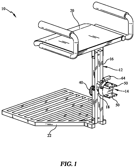
Rotating tree stand
A hunting tree stand with a wheel housing strapped to the trunk, so the seat frame swivels around the tree.
US 11,257,243 B2 · Title as filed: Target shooting system · Inventors: Wiley; Stephen et al.
Sheet 1 of 7 from the published document. All sheets in the USPTO PDF
Paper targets printed with markers and barcodes so a camera can find the target and score every shot automatically.
A shot detection system can include a shooting target that is made of paper and printed to include fiducials, borders and a bar code together with a scoring region and markings. A method of camera adjustment control can find and lock onto a target. A target acquisition procedure can include extracting a region of interest (image of the shooting target), calibrating the region of interest and then target locking. The real-time target locking procedure can include correcting an image of the region of interest to account for tilt, rotation and skew. A methodology of shot detection can include acquiring probable and confirming shot candidates and then verifying the probably shot candidate with the confirming shot candidates to substantially eliminate falsely identified shots candidates, thereby significantly improving performance and experience.
Many target shooting systems exist to provide additional information to a target shooter. These systems attempt to provide the shooter with visual and statistical information about their shooting habits and performance. Specifically, shot detection systems have been created to help a target shooter identify where their shots are hitting the target. The way these target shooting systems work is widely variable. A problem with camera based shot detection systems has been that they are limited by their inability to work in all of the typical shooting environments and across variable shooting distances. Other problems with camera based shot detection systems have been that they require additional light sources or projectors, require user input for shot detection, or are limited to a narrow range of operating conditions. U.S. Pat. No. 4,204,683 to Filippini, et al. discloses a closed video ci
The first 3 of 7 drawing sheets from the published document, cropped to the drawing. Every sheet is in the USPTO PDF.
Independent claims and the claims that build on them, read from each claim's text.
What the patent claimed, word for word. All of it is now free to use.
The present invention relates to target shooting and, in particular, to a target shooting shot detection system. The system provides a solution for automatic detection of shots using standard paper shooting targets in all typical shooting environments and at all typical shooting distances without the need for supplementary devices to assist with target identification or shot detection processes.
Many target shooting systems exist to provide additional information to a target shooter. These systems attempt to provide the shooter with visual and statistical information about their shooting habits and performance. Specifically, shot detection systems have been created to help a target shooter identify where their shots are hitting the target. The way these target shooting systems work is widely variable. A problem with camera based shot detection systems has been that they are limited by their inability to work in all of the typical shooting environments and across variable shooting distances. Other problems with camera based shot detection systems have been that they require additional light sources or projectors, require user input for shot detection, or are limited to a narrow range of operating conditions.
U.S. Pat. No. 4,204,683 to Filippini, et al. discloses a closed video circuit for detecting shots on a target where the point of impact is determined by light influenced by a projectile prior to hitting the target.
U.S. Pat. No. 4,949,972 to Goodwin, et al. discloses a system for determining projectile location relative to a target. This system utilizes a target support structure with light emitting and receiving devices which generate output signals indicative of the location of the projectile during passage through the target area.
U.S. Pat. No. 5,577,733 to Downing discloses a targeting system which projects a light panel from a projector onto a target. A bullet from a gun passes through the light panel which sends signals indicative of the bullet's location and velocity to a computer which analyzes and displays the data.
U.S. Publication No. 2006/0150468 to Zhao discloses a video-monitor system to display the target image on screen.
Heretofore, the requirements of shot detection working in all of the typical shooting environments and across all of the typical variable shooting distances referred to above have not been fully met. Also, the shortcomings of requiring additional light sources or projectors, requiring user input for shot detection, or being limited to a narrow range of operating conditions referred to above have not been fully solved. In view of the foregoing, there is a need in the art for a solution that simultaneously addresses all of these requirements and problems.
Embodiments of this disclosure provide a solution for automatic detection of shots using standard paper shooting targets without the need for supplementary devices to assist with target identification or shot detection processes. Embodiments can include a digital camera with a motorized optical zoom lens, vision processing software (vison algorithm) on-board a computer processing unit connected to the camera, and shooting targets that are printed to optimize working with both the camera and its lens and the vision processing software. Embodiments can include printed paper shooting targets that are printed with fiducials, a border and other markings to optimize system performance and provide the system with information required to perform automatic system calibration, shot detection and shooting performance analysis. The vision processing software can compensate for target movement, change of distance and non-uniform lighting conditions.
Embodiments of this disclosure can include a target shooting system that includes a shooting target. The shooting target can be made of paper and printed to include a plurality of fiducials having centers that enable a machine vision system having a vison algorithm to correct for target movement, tilt, rotation and skew. The centers of the fiducials also enable the vision algorithm to define a virtual coordinate mesh to uniquely label detected shot candidates. The shooting target can include a border defining a shooting area. The target can include a machine readable identifier such as a barcode or other indicia to identify the target type and its associated shooting area markings for scoring purposes.
Other embodiments of this disclosure includes a methodology of camera adjustment control to find and lock onto a target. These embodiments can include target acquisition procedures based on extracting a region of interest (image of the shooting target), calibrating the region of interest. These embodiment can also include real-time target locking procedure that can include correcting an image of the region of interest to account for tilt, rotation, and skew.
Another embodiment of this disclosure includes a methodology of shot detection. The shot detection procedure can include acquiring probable shot candidates and confirming shot candidates and then verifying the probable shot candidate with the confirming shot candidates to substantially eliminate false positives, thereby significantly improving performance, accuracy and experience.
In the detailed description of the preferred embodiments presented below, reference is made to the accompanying drawings.
FIG. 1 is a perspective view of a shot detection system.
FIG. 2 is a portrait view of a paper target including a plurality of fiducials, a border and a barcode location.
FIG. 3A is a flow diagram of a target acquisition process for use with a camera with preset zoom value steps that can be implemented by a computer program.
FIG. 3B is a flow diagram of a target acquisition process for use with a camera without preset zoom value steps that can be implemented by a computer program.
FIG. 3C is a flow diagram of a target acquisition process in a static camera and target situation that can be implemented by a computer program.
FIG. 4 is a flow diagram of a real-time target locking process that can be implemented by a computer program.
FIG. 5 is a flow diagram of a shot detection process that can be implemented by a computer program.
In the description that follows, like parts are marked throughout the specification and figures with the same numerals, respectively. The figures are not necessarily drawn to scale and may be shown in exaggerated or generalized form in the interest of clarity and conciseness.
Referring to FIG. 1 , a target shooting system can include target 110 with directional fiducials 120 and border 130 for tracking a position of the target. More generically, the target can be termed a shot detecting object. The target can be made of any suitable material such as plastic, foam core, wood, linen, etc., and the invention is not limited to paper targets. The target is viewed by camera 140 which can be encapsulated within protective enclosure 145 that can be mounted to adjustable swivel head 150 which can be fixed to a bar or stand positioned behind the line of fire. In alternative embodiments, the camera can be located at the line of fire, or even down range of the line of fire. The target is spaced a flexible shooting distance (d) from the line of fire behind which a shooter is located. The camera is coupled to, and interfaced with, computer 160 (computation unit) that can be positioned in close proximity to the camera. In alternative embodiments, the computer can be located elsewhere. A program (vison algorithm) executed by computer processes real time streaming frame data 170 (artist's conceptualization of a series of images) provided by the camera to find and lock the target and then determine the presence and virtual coordinate mesh locations of shots 190 that are on-target. In addition, the vison algorithm program can process other shooting performance metrics such as score (based on target design), timing of shots, which shots in a series (string) are on-target, trends in drift and/or rise during a series and group size. The information output by the program can be displayed on display unit 180 that can be positioned in close proximity to the computer. In alternative embodiments, the display can be located elsewhere. A program (user interface) executed by the computer processes data for the display, and other user interface devices which can be present such as a touch screen, a microphone, a speaker, headphones, a buzzer and/or lights. A program (middleware) executed by the computer processes data from and to the camera and its lens and other data acquisition devices which can be present such as lights, lasers, additional camera(s) and/or a microphone.
In a preferred embodiment, the display unit includes a touchscreen monitor and the shooter interfaces with the touchscreen monitor to control the target shooting system. The touchscreen monitor can be mounted to an adjustable arm (not shown) so that the monitor position can be adjusted by the shooter for optimal viewing of the monitor. In an alternative embodiment, the information output by the program can be displayed on a separate wireless device such as a cell phone or even a heads-up display located within glasses, goggles, a visor or a face shield. Shots 190 that are on-target leave holes (perforations, apertures) in the paper target can be detected by the camera and shown on the display unit in less than approximately 2.0 seconds, preferably less than approximately 1.0 second and, more preferably less than approximately 0.2 seconds.
The targets are designed with graphic features to enable the system to automatically find the target at a distance down range from the line of fire of from approximately 3 yards to more than approximately 500 yards. When the camera is provided with a suitable high magnification lens, the system can function at a range of more than 1,000 yards. After finding the target, the system can zoom into the target for optimal resolution, adjust other camera settings, lock onto the target and correct for target positioning to straighten the target relative to the camera, and remain locked throughout the shooting session for optimal performance even if the target moves (within camera view) due to environmental factors. Optionally, the camera can be connected to a motorized mounting to pivot (pan) the camera to increase the useable zoom range while keeping the target centered in the field of view of the camera or even to expand the effective field of view of the camera during target acquisition. The computer algorithm can directly control the camera's settings (such as, but not limited to, exposure gain, white balance, zoom, and focus) based on real time image analysis to achieve an optimum image for shot detection processing.
Referring to FIG. 2 , target 200 includes three primary features which enable the target shooting system functionalities described above. The three primary features of the target are target border 210 and directional fiducial markings 220 , scoring region outlines and markings 230 , and target barcode 240 . The target border and fiducial markings are optimized in terms of color, size, shape, line thickness, and polarity. The target border facilitates real-time online target locking (tracking) and defines an on-target shooting area. The directional fiducials facilitate real-time online target acquisition and locking. The fiducial centers can define dimensions (x,y) that enable the computation unit to define/calibrate the algorithmic virtual coordinate mesh system in real time. The fiducials can be expanded to occupy larger fiducial area 225 to facilitate target acquisition at longer range and/or suboptimal lighting conditions. The color blue can be advantageously used to print the fiducials and border because the color blue has unexpectedly been found to facilitate operation of a digital camera in accord with embodiment of this disclosure for the purposes of target acquiring, extracting and tracking under shooting range environmental conditions such as lighting, target movement, vibration, smoke and humidity. The scoring region outlines and markings are optimized in terms of color, size, shape, and line thickness. These characteristics of the scoring region can be associated with a look-up table stored in the computation unit. The look-up table can be based on a target identifier such as, for example, a barcode. The barcode is optimized in terms of camera detection with regard to color, size, shape, line thickness, and barcode style. The barcode can be a 1D (1 dimensional) linear barcode or a 2D (2 dimensional) matrix barcode or other marking for identification of the target and look-up of characteristics such as the dimensions x, y and the shooting area markings for scoring purposes.
Referring to FIGS. 1-2 , camera 140 can include a motorized zoom lens, an imaging sensor coupled to the lens, a camera control board coupled to the sensor, and a data transmission interface coupled to the board. The camera can be coupled to a protective enclosure that is coupled to an adjustable head that is coupled to a mounting bar or stand. These components enable the system to detect target 110 , 200 at a position on the shooting range, optimize the camera settings for ideal system performance using software, and transmit the captured image data to the computer in a way that the computer can easily pass the data along to the program. The motorized zoom lens is selected to allow automated control over the zoom, focus, and aperture of the lens. The zoom lens enables maximum variation in target distance across both close and far distances under a wide variety of lighting conditions. The data transmission interface processes and transmits the image data using a protocol that the computer is able to interpret and pass along to the program with sufficient speed and minimal data size. The protective enclosure protects the image sensor, lens, control board, and data transmission interface from the range environment. The adjustable head allows for quick camera position adjustment and prevents unwanted camera movement. The bar or stand provides a base for the camera to mount to a wall, floor, or ceiling. Other embodiments of camera mounting can include a portable case or container that allows the camera to sit on the ground.
The computer can include a power supply to provide power to all system components, a cooling system to keep operating temperatures low, an enclosure to protect the computer components from the range environment, interface ports to connect to the camera and touchscreen monitor, a graphics card to output the information to be displayed on the monitor, storage space to save data, wi-fi connectivity to enable remote access to the system and cloud access for additional data storage, and a central processing unit which enables the maximum performance of the system with a minimal footprint.
The program which is executed by computer 160 is able to control the camera to optimize the camera settings to be able to find the target, zoom in to the target, optimize the image of the target, detect the markings of the target, create a virtual coordinate mesh of the target, detect the location of new shots on the target, and determine shooting performance metrics such as score, timing and group size based on the detected shots.
Display unit 180 can be a touch screen monitor and interfaces with the computer 160 . The monitor displays data output from the program. The monitor can allow touchscreen control of the system. The monitor can be mounted to an adjustable arm to allow the shooter to physically position the monitor for ideal viewing of the display.
A plurality of target fiducials allow software to acquire a target and continuously lock-onto a target (and subsequently define an origin for a virtual coordinate mesh) in real-time even while the target is moving. The target fiducials allow for software correction of target tilt, rotation, and skew. The target fiducials also allow for software correction of folds and/or creases in the shooting target. A border defines a shooting area. A barcode identifies the type of target to associate target properties such as dimensions and shooting area markings. This enables embodiments of this disclosure to create a substantially perfect target image to analyze from an imperfect environment.
Referring to FIGS. 1 and 2 , physical targets with fiducial marks can be recorded by the camera. Then the data from the camera can be processed by the computation unit. By utilizing these fiducial marks, the computer algorithm can capture and analyze optimum, correctable images from an imperfect environment.
In a shooting range environment, a target is subject to real-world conditions such as moving air (wind, ventilation draft, etc.) and changing lighting conditions (other shooting lanes becoming active or going dormant). As projectiles strike target 110 , the target may move back and forth or side to side. As this occurs, the fiducial marks on the target assist the algorithm in understanding exactly where the target lies within the image captured by the camera. This means that as one image is compared to another for shot detection, the target does not have to be in the exact same physical location in order to achieve accurate detection of shots. This is an important and commercially significant advantage of embodiments of this disclosure.
One of the most significant advantages to using a system with known targets is that it allows for a clear definition of scoring regions. Since the fiducial marks and borders will provide a clearly defined origin and since the space within the shooting area is known (x and y), the system will always know definitively where a bullseye or other scoring region lies.
The fiducial marks and borders assist in rendering a corrected virtual coordinate mesh overlay on the target including its shooting area for scoring purposes. By using four defined corners, the algorithm can correct for imperfections in the target such as tilt, rotation, and skew (as well as folds and creases in the shooting target).
The system is designed to work at a close range (such as 3 yards) up to as far of a range as the camera lens is capable of magnifying to. The fiducial marks allow the distance between the target and the fixed camera to be variable. A target that is farther from the camera will appear smaller in the camera's field of view at a given zoom setting. The fiducial marks assist the computer algorithm in knowing the size of the target in the image frame and can therefore adjust shot detection tolerances based on the target size. This adjustment increases overall system reliability and significantly reduces false positive detection. The reduction of false positives is a major commercial advantage of embodiment of this disclosure.
While a user shoots at a target, the speed at which the shot detection feedback is presented to them is important for effective training. In order to detect every shot on-target quickly, the algorithm should process only the minimum amount of data that is needed. The fiducial marks allow the algorithm to know exactly where the shooting region is within the image and analyze only that data. Specific markings and coloring of the fiducials and borders allow the shooting region information to be extracted quickly and efficiently.
Other identifiers on the target may also be used to assist the algorithm in determining other required pieces of information such as target type, style, and revision. These identifiers may be in the form of a printed marking on the target or through another way of applying a marking to a target (such as a sticker).
One possible version of the aforementioned target with fiducial marks is a printed version on a physical piece of paper. Similar fiducials and border can also be printed on a physical piece of cardboard or other type of substrate. The fiducials and border can be ink, coatings, lamination or other materials to apply fiducial marks and identifiers. Embodiments of the invention can include a projection on a (semi-)reflective surface such as a replaceable screen based on a roll of paper and a take-up roll. Embodiments of the invention can include 3-D targets composed of foam where a surface of the foam is a first color (e.g. dark brown) and an interior of the foam is a second color (e.g. white) that contrasts with the first color. The fiducials and border can be affixed with adhesive or laminated to the surface of the foam. In the case of a 3-D target, a virtual coordinate mesh could be a virtual overlay virtually spaced apart from the compound curve surface of the target.
A fiducial marker or fiducial is an object placed in the field of view of an imaging system which appears in the image produced, for use as a point of reference or a measure. In accord with embodiments of this disclosure, a fiducial can be either something placed into or on the imaging subject, namely the shot detecting device (e.g. paper target). In preferred embodiments of the invention, the design of the fiducial is optimized to allow for both target acquisition and locking (tracking) as well as efficient use of the available target for a shooting area. Typically, this will result in the fiducials being located in the corners of a target. The shape of the target can be square, rectangular, round, polyhedral or other shape. While FIG. 2 shows a rectangular embodiment with checkerboard fiducials and solid borders connecting the four fiducials, the invention is not limited to checkerboard or another particular format of fiducial.
The checker board pattern fiducial is easy to detect with a pattern match algorithm. In a preferred embodiment, the vision algorithm uses corner detection to detect possible chessboard corners, together with phase detection to verify if a possible corner is a chessboard corner. The center of the fiducial can be precisely located using edge detection within the checkerboard pattern.
Preferably, each square in the checkerboard is either the color of the paper (e.g. cream white) or the color of the border (e.g. blue). This choice of colors is preferred because it facilitates rapid, accurate and precise operation of the machine vision algorithms. In a preferred embodiment, by varying the fill within the squares, each individual corner can be identified with a fiducial.
The colors of the fiducials are preferably white and blue. Since the paper of the target is typically a shade of white, the white squares of the fiducials can simply be left as unprinted areas of the paper. Since the blue squares of the fiducials are typically printed on the paper, the color of the blue can be usefully represented by printing industry standard CMYK color model values. Preferably, the blue squares can be printed areas characterized by CMYK color model values of C=approximately 100, M=from approximately 25 to approximately 100, Y=approximately 0, and K=0 to approximately 80. The borders of the target are preferably also blue printed areas with the same range of CMYK characteristics as the fiducials.
The choice of paper and ink can be important to optimizing performance of embodiments of the invention because the difference (delta) between a) the light reflected by the paper or ink and b) no light reflected by the paper or ink due to an aperture caused by a shot is the raw data for shot detection. Thus, embodiments of this disclosure do not require a light source located on the opposite side of the target from the camera lens.
The paper on which the fiducials and borders are printed will now be described. The paper size can advantageously be sized from approximately 30″×approximately 60″ to approximately 8″×approximately 10″; preferable a standard size of approximately 24″×approximately 45″ for target range familiarity. The paper weight bond can advantageously be from approximately 19 # to approximately 31 #, preferably approximately 20 # for economy.
Internationally, whiteness is the most commonly used measure as defined by the CIE (Commission Internationale de l'Eclairage—International Commission on Illumination) whereas in the US the most commonly seen measure is brightness as defined by the TAPPI (Technical Association of the Pulp and Paper Industry). Shade represents the color of the paper measured on the CIE LAB model (more formally known as CIE L*, a*, b*).
The CIE measure of whiteness is a measurement of the light reflected by the paper across the visible (daylight) spectrum. The CIE have set a standard of D65 illumination which is a standard representation of outdoor daylight under which the amount of light reflected is measured. For a perfect reflecting non-fluorescent white material, the CIE whiteness would be 100, however most commercially available ‘white’ paper has CIE whiteness measures of between 130 and 170 due to the addition of optical brightening agents (OBAs) which are designed to reflect light from the non-visible range (mainly ultra-violet) back in the visible spectrum. The lighting conditions under which the paper is viewed may well affect how a person sees the paper, paper that has a high whiteness achieved by adding large amounts of OBA to a fairly dull original sheet it may appear to be bright outside but less bright under indoor lighting conditions. On the other hand, a sheet with a good white base but low amounts of OBA will compare well under indoor lighting but may appear duller outdoors. This phenomenon is known as Metamerism. For indoor target use, it can be an advantage to use a paper with a good white base and lower amounts of OBA. Conversely, for outdoor target use it can be an advantage to use paper with higher amounts of OBA. For targets according to embodiments of the invention it can be an advantage to use paper with a CIE whiteness of from approximately 92 to approximately 99 because this gives less glare at lower cost and produces less strain on the eyes. This choice of whiteness can be preferred because less glare facilitates rapid, accurate and precise operation of the machine vision algorithms.
Brightness, as specified by the TAPPI is the measurement of the amount of reflectance of blue light (Wavelength 457 nanometers, 44 nm wide). There is also an ISO standard for measuring brightness (ISO 2469—Paper, board and pulps—Measurement of diffuse radiance factor) but this is rarely used as the CIE whiteness scale is the more common measurement. As with whiteness it is common to see brightness measurements of over 100, which means that more light is reflected than was originally shone on the paper due to Optical Brightening Agents reflecting part of the ultra-violet spectrum back in the visible spectrum. Measurement for TAPPI brightness are often in the 110-120 range, lower than commonly found CIE whiteness measures as the OBA's only have a small spectrum to reflect from the standard dictated blue light source. For targets according to embodiments of the invention it can be an advantage to use paper with a TAPPI brightness of from approximately 90 to approximately 98 because this gives less glare and produces less strain on the eyes. This range of brightness can be preferred because less glare facilitates rapid, accurate and precise operation of the machine vision algorithms.
A true white paper will reflect all the colors of the spectrum equally, whereas a blue white shade absorbs some of the longer wavelength red light and reflects more of the shorter wavelength blue light; conversely a cream white shade absorbs more blue light and reflects more of the red light. For targets according to embodiments of the invention it can be an advantage to use a more neutral, natural or cream white shade because this gives less glare and produces less strain on the eyes. This choice of shade can be preferred because less glare facilitates rapid, accurate and precise operation of the machine vision algorithms.
The paper used for the target can be a reactive splatter paper to improve shot detection in difficult low light conditions. Reactive splatter paper generates a contrasting corona when a shot is on-target.
The algorithms used for detection of the fiducials are robust to account for missing parts of the fiducials because they may be shot out. The robustness can be provided by computing a virtual fiducial that includes the missing parts based on the remaining parts of the fiducial that are sensed by the camera and recognized by the software. This can also include computing a complete virtual fiducial based on other fiducials that are sensed and recognized. The algorithms are also robust to account for missing parts of the border(s), barcode and/or shooting area markings because they may be shot out as well.
The border is specified to be an optimal width based on the size of the target in the image at the maximum distance. The width of the border is specified to be at least 10 pixels at this furthest distance. This contrast in color and the width of the border is used with an algorithm like a Hough transform to detect the presence of the border. The precise location is then determined by using an edge find algorithm.
The algorithms used are resilient to missing parts of the border that can be shot out. It is likely that a given target will eventually sustain physical damage during use, especially if the groups are small. When part of the border is missing, the algorithms can proceed based on extrapolating the missing portion of the border based on those portions of the border that are still intact and the fiducials.
The design of the target shooting area is optimized to include only colors and patterns which do not interfere with shot detection. For instance, white and green are optimal target colors for shot detection. Conversely, most shades of black, blue and/or gray can be advantageously avoided because they interfere with shot detection. The shooting area can include suitable markings such as a silhouette or bullseye (or other type of markings).
Camera adjustment/control to find and lock-onto a target can include software that uses camera controls such as: zoom, white balance, exposure gain, focus, shutter speed, aperture control, contrast and brightness. This software utilization of the camera controls can automatically find the target in the field of view and adjust settings to optimize shot detection. The target fiducials and borders are used along with the camera controls.
To successfully find the target in the cameras field of view and lock onto a target at a flexible shooting distance, the algorithm should automatically adjust camera settings to find the target and then further adjust camera settings to optimize the image in order to lock onto the target fiducials.
When the target acquisition procedure is initiated, the algorithm will load initial camera settings. Once the settings are loaded, an image is captured and the algorithm will attempt to extract the target from the image using the targets directional fiducials and target borders. If the target extraction process is not successful at finding the target, camera settings are adjusted and target extraction is re-attempted. If the target extraction process is successful, the algorithm will assign a confidence level to the camera settings which will be added to a cache of camera settings which result in the target being found.
The algorithm will continue to adjust camera settings and attempt to extract and find the target until camera settings adjustment results in the target not found. Once the algorithm encounters the target not found condition, it will evaluate the camera settings stored in the cache and load the set of camera settings with the highest confidence level at the closest zoom distance acquired.
After the coarse camera settings are loaded to the camera, the algorithm enters a “fine tuning mode” to optimize the camera settings for the real-time target locking procedure. The first step of the fine tuning process is to carry out a color balance check. If the color balance of the image is not optimal, the algorithm will recalibrate the color balance to produce an optimal image.
Once the optimal color balance is achieved, the algorithm will move onto the fine tune brightness step. If the color balance check returns that the color balance is already optimal, the algorithm will skip the recalibrate color step and move directly to the fine tune brightness step. The fine tune brightness step checks the brightness of the target image and using settings such as exposure gain, shutter speed and aperture adjustment to recalibrate the cameras brightness settings based on whether the target image is over or under exposed.
Once the optimal target brightness is achieved, the target location and optimized settings are saved so that the real-time target locking procedure can be carried out. The information in the target image will be extracted to find the Blue target fiducials and border. Once the target fiducials and borders are extracted, the algorithm will compute the locations of the fiducials. This process will be carried out over a series of captured images.
Referring to FIG. 3A , an example of a target acquisition procedure is illustrated. This target acquisition procedure embodiment is for when the distance between the target and camera may vary (e.g. 10 yards, 25 yards, etc.) and pre-calibrated camera settings are going to be used. In this embodiment, when moving toward each distance a vison algorithm does not perform “calibrate image”, and it relies on settings loaded from a preconfigured file that have already been calibrated at each distance (offline calibration).
Still referring to FIG. 3A , this target acquisition procedure embodiment begins with captured image input 300 . Extract target (ROI) process 305 is performed on the captured image. The extract target process can include recognizing a plurality of fiducials. The extract target process can include defining and extracting a region of interest for further analysis by cropping the region of interest or target from the image. Decision 310 , if a target is found, then the procedure advances to a cache distance and camera settings process 315 . The cache distance and camera settings can include saving a region of interest (ROI) that includes the shooting area of the target as well as camera settings such as lens zoom step, focus, aperture and the camera color balance and brightness. These camera settings are saved as settings that allow the vison algorithm to successfully extract the target from the image. The procedure then advances to a move to next distance and load camera settings process 320 . The move to next distance and load camera setting process loads preset camera settings including the next zoom value step preset and adjust the camera settings according to the loaded presets. The move to next distance and load camera settings process can include adjusting the camera zoom, focus, color balance, brightness and even direction if the camera is mounted on an actuatable motor driven swivel head.
Alternatively, at decision 310 , if no target is found, then the procedure advances to decision 325 . At decision 325 , if a target has not previously been found resulting in a cache of camera settings, then the procedure goes to the move to next distance and load camera settings process 320 and then back to captured image input 300 . Alternatively, at decision 325 if a target has been previously found, then the procedure advances to load best candidate from previously cached settings output 330 . From the previous presets cached at cache distance and camera settings process 315 , the load best candidate from previously cached settings process 330 can use the preset with a shortest distance to target (highest zoom value) and load those camera settings. This comparison and choice of the best candidate is an important feature and commercial advantage of embodiments of this disclosure because this output/input selects the cached settings that are most likely to result in an optimized result after finetuning. The target acquisition procedure then proceeds to a calibrate image based on region of interest subroutine 350 . This calibration of the image coming after load best candidate from previously cached settings process 330 is based on the region of interest. The calibration can include the vision algorithm iteratively tuning camera settings for color balance and brightness. Feedback for each iterative step can be calculated within the region of interest.
Still referring to FIG. 3A , at the calibrate image based on region of interest subroutine 350 , an adjust color balance based on region of interest process 335 is implemented. This is a finetune of the color balance. This can include a step of recompute camera color balance setting based on a region of interest (target area) and adjust setting such that RGB color channel to achieve correct white balance inside the region of interest. A preferred “correct” white balance in this scenario is when R=G=B (red intensity=green intensity=blue intensity). It should be noted that this balance is specifically achieved on the white portion of the target and not on the entire target. At decision 337 , a determination is made of whether the color is balanced based on one or more criterion. If no, then the procedure loops back to the adjust color balance based on adjust color balance based on region of interest process 335 . Alternatively, at decision 337 if the color balance is acceptable based on the one or more criterion, then the procedure advances to adjust brightness based on region of interest process 340 .
Still referring to FIG. 3A , at adjust brightness based on region of interest process 340 , a brightness adjustment of the region of interest is begun. This is a fine tune of the brightness. This can include a step of recompute camera brightness setting based on the region of interest and adjust the setting to achieve optimized brightness in the region of interest. At decision 342 , a determination is made of whether the brightness is optimized based on one or more criterion. If no, then the procedure loops back to adjust brightness based on region of interest process 340 and then again to decision 342 . Alternatively, at decision 342 if the brightness is acceptable based on the one or more criterion, then the procedure advances to extract and lock target process 345 . At the extract and lock target process, the target can be cropped from the image (extract target). The process can also include computing the fiducial centers on the target and making sure the polarity and contrast of the extracted fiducial centers meet a set of criteria. Finally, the extracted and locked target is presented at acquired target output 347 .
Referring to FIG. 3B , another example of a target acquisition procedure is illustrated. This target acquisition procedure embodiment is for when the distance between the target and camera may vary and pre-calibrated camera settings are not going to be used. In this embodiment, at each distance the vison algorithm calibrates an image at each distance if needed (e.g. when the target is not found) without relying of pre-calibrated settings; all camera settings are computed on-the-fly (online calibration). The embodiment shown in FIG. 3B does not utilize preset zoom value steps making the choice of distance between target and camera infinitely variable within a range (e.g. from approximately 3 yards to approximately 50 yards or more) with the tradeoff being more time may be required for acquisition without presets.
The description continues in the full USPTO document.
Fees are due 3.5, 7.5 and 11.5 years after grant. This patent expired on February 22, 2026, so the fee marked "not paid" was the one that went unpaid.
TARGET SHOOTING SYSTEM
Filed Aug 2019 · published Mar 2021Target shooting system
Filed Aug 2019 · granted Feb 2022Earlier publications, parents and continuations. None of them can still be enforced, or this patent would not be listed.
Prior art cited by the examiner or applicant. Useful when you check your own idea for novelty.
Names, summaries, modern angles and build ratings are Patent Yard's editorial notes. Everything else on this page comes from the documents linked above.