 Lapsed, fee not paid7 drawings
Sports & Fitness · US 11,257,243 B2
Camera-scored paper targets
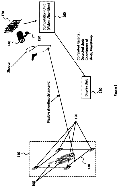
Paper targets printed with markers and barcodes so a camera can find the target and score every shot automatically.
US 11,207,561 B1 · Title as filed: Portable pushup grips · Inventors: Stevenson, III; James Oliver et al.
Sheet 1 of 7 from the published document. All sheets in the USPTO PDF
Pushup handles whose bases spring-lock on, so they pack flat and set up in seconds.
The present invention is described as one set containing a pair of pushup grips. Each grip includes a longitudinal hand support connected to two separate base supports. Each base support has a spring-loaded connection mechanism for rotation between a compact storage position and an active engaged position. The base supports are identical configurations, with a channel through the top of the length for the storage position, a channel through the top of the width for the active position, with a dampening tread covering the bottom of each base support. The longitudinal hand support optionally includes padding for added hand comfort and ring connectors on each end cap to attach to a resistance band.
Exercise is at an all-time high, with a growing trend toward exercise as a social activity. Fitness centers, gyms, and exercise classes are commonplace in almost any location. A main staple of exercise routines—one of the most common exercises—is the pushup. Popularity of the pushup is evidenced by the plethora of pushup grips currently on the market. Prior art focuses on enabling an improved hand position off the ground to prevent strain on the wrists. Often the grips are also designed to enable an enhanced exercise using rotation or resistance. The problem with the prior art is the bulkiness and size of the grips. For those wishing to travel or wanting to use their own equipment for classes, the prior art grips are not appropriately sized or configured for convenient mobility and transport.
The first 3 of 7 drawing sheets from the published document, cropped to the drawing. Every sheet is in the USPTO PDF.
Independent claims and the claims that build on them, read from each claim's text.
What the patent claimed, word for word. All of it is now free to use.
This invention relates generally to exercise equipment. Specifically, this invention relates to portable pushup hand grips.
Exercise is at an all-time high, with a growing trend toward exercise as a social activity. Fitness centers, gyms, and exercise classes are commonplace in almost any location. A main staple of exercise routines—one of the most common exercises—is the pushup. Popularity of the pushup is evidenced by the plethora of pushup grips currently on the market. Prior art focuses on enabling an improved hand position off the ground to prevent strain on the wrists. Often the grips are also designed to enable an enhanced exercise using rotation or resistance. The problem with the prior art is the bulkiness and size of the grips. For those wishing to travel or wanting to use their own equipment for classes, the prior art grips are not appropriately sized or configured for convenient mobility and transport.
Portable pushup grips are described herein. The present invention is described as one set containing a pair, or two, of the pushup grips—one for each hand. Each grip includes a longitudinal hand support connected to two separate base supports. Each base support has a spring-loaded connection mechanism for rotation between a compact storage position and an active engaged position. The base supports are identical configurations, with a channel through the top of the length for the storage position, a channel through the top of the width for the active position, and a dampening tread covering the bottom of each base support. The longitudinal hand support optionally includes padding for added hand comfort and ring connectors on each end cap to attach to a resistance band.
FIG. 1 illustrates a pair of portable pushup grips in use.
FIG. 2 illustrates a singular pushup grip in the active position.
FIG. 3 illustrates a singular pushup grip in the compact position.
FIG. 4 illustrates the assembly.
FIG. 5 illustrates the spring-loaded connection.
FIG. 6 illustrates the base support tread.
FIG. 7 illustrates an optional ring at the ends to attach to a tensioning apparatus.
The present invention includes a set of pushup grips that are designed to be compact and portable. The disclosed invention comprises a first and a second pushup grip to form a pair of grips used for traditional pushup exercises as illustrated in FIG. 1 , but the grips may be used singularly for one-armed pushup exercises. The first and second grips are identical and, as such, will hereinafter be described as a singular pushup grip.
As shown in FIG. 2 , each pushup grip has a longitudinal hand support 10 that has two identical base supports 12 . Each base support 12 moves from an engaged active position 15 as illustrated in FIG. 2 to a compact storage position 20 as illustrated in FIG. 3 . Each base support 12 has a first channel 13 through the top side of its length, enabling the hand support 10 to rest horizontally in the first channel 13 of the base support 12 to form the compact storage position 20 . The base support 12 has a second channel 14 through the top side of its width, enabling the hand support 10 to rest horizontally in the second channel 14 of the base support 12 to form the engaged active position 15 . The base support 12 rotates between the compact storage position 20 and the engaged active position 15 by pulling on the base support 12 and rotating the base until it rests in the respective channel of the desired position, either the engaged active position 15 or the compact storage position 20 .
Each base support 12 is connected at an end of the hand support 10 by a spring-loaded connection mechanism 16 , as shown in FIGS. 4-6 . The connection mechanism 16 extends into an aperture at the bottom center of the base support 12 through its entirety and protrudes out an aperture 11 at the top center of the base support. The connection mechanism 16 extends into an end slit 17 at the bottom the hand support 10 to the top interior of the hand support, with a spring 22 and a stabilizing component 18 sitting at the interior of the hand support 10 , and threading 26 and a nut 28 located within the base support 12 . The stabilizing component 18 may be a washer or a custom molded piece that helps secure the hand support 10 onto the base support 12 . The end slit 17 is located at the bottom of each end of the hand support to allow for sliding the connection mechanisms into place during assembly, as shown in FIG. 5 . There is a cap 24 with a securing protrusion 34 at each end of the hand support 10 that fits snugly within the interior of the hand support to a depth that would press against the stabilizing component 18 to secure the position.
The preferred embodiment of the hand support is cylindrical and hollow for lightweight comfort, but may also take other geometric forms and be of a solid configuration. As shown in FIG. 7 , the pushup grips may be used in combination with a tensioning band 30 for resistance exercises, wherein each hand support 10 includes a connector ring 32 at the outside end of the cap 24 . An elastic band 30 may be attached to the connector ring 32 at the outside of each hand support 10 for resistance training. Each connector ring 32 must be strong enough to support tension from a resistance band. The preferred embodiment of such a connector is a metal ring, but may also include a rope component. The end caps 24 are glued to the inside of the hand support 10 and may additionally or alternatively have outside threading to secure to inside threading of the hand support 10 .
The preferred embodiment of the base supports 12 has a longer length than a shorter width, as shown in FIGS. 2-3 , having a bottom portion of the base support that is wider than the top portion. The preferred embodiment also includes a rubber or foam tread piece 36 at the bottom of the base support to prevent slippage and also provide cushioning, with a soft or hard grip made of a type of foam, rubber, or plastic covering the hand support for added comfort.
Fees are due 3.5, 7.5 and 11.5 years after grant. This patent expired on December 28, 2025, so the fee marked "not paid" was the one that went unpaid.
Portable Pushup Grips
Filed Jun 2020 · published Dec 2021Portable pushup grips
Filed Jun 2020 · granted Dec 2021Earlier publications, parents and continuations. None of them can still be enforced, or this patent would not be listed.
Prior art cited by the examiner or applicant. Useful when you check your own idea for novelty.
Names, summaries, modern angles and build ratings are Patent Yard's editorial notes. Everything else on this page comes from the documents linked above.