 Lapsed, fee not paid3 drawings
Agriculture & Food Tech · US 8,677,845 B2
Grain bin sensor pendulum
A protected pendulum of sensors hung in stored grain that measures temperature and moisture from inside the pile.
US 11,206,772 B2 · Title as filed: Grow media systems, apparatuses, and methods · Inventors: McKenna; Shane
Sheet 1 of 15 from the published document. All sheets in the USPTO PDF
A grow medium with a stiff support layer bonded to a wicking layer, stood on edge to feed roots.
A grow media includes a layered grow media including a mechanical support structure layer and a wicking structure layer. The mechanical support structure layer and the wicking structure layer are coupled together in a vertical configuration.
Hydroponics is one method of growing plants without soil using mineral nutrient solutions in water. Various grow media have been utilized in conjunction with hydroponics but each have shortcomings, problems, and disadvantages. The subject matter of the present application has been developed in response to the present state of the art, and in particular, in response to the problems and disadvantages associated with conventional protective grow media that have not yet been fully solved by currently available techniques. Accordingly, the subject matter of the present application has been developed to provide embodiments of a system, an apparatus, and a method that overcome at least some of the shortcomings of prior art techniques. Additionally, the subject matter may be used in conjunction with soil or other organic materials.
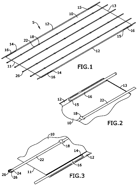
The first 3 of 15 drawing sheets from the published document, cropped to the drawing. Every sheet is in the USPTO PDF.
Independent claims and the claims that build on them, read from each claim's text.
What the patent claimed, word for word. All of it is now free to use.
This invention relates to grow media and more particularly relates to a grow media in hydroponic environments, geoponic environments, etc.
Hydroponics is one method of growing plants without soil using mineral nutrient solutions in water. Various grow media have been utilized in conjunction with hydroponics but each have shortcomings, problems, and disadvantages. The subject matter of the present application has been developed in response to the present state of the art, and in particular, in response to the problems and disadvantages associated with conventional protective grow media that have not yet been fully solved by currently available techniques. Accordingly, the subject matter of the present application has been developed to provide embodiments of a system, an apparatus, and a method that overcome at least some of the shortcomings of prior art techniques. Additionally, the subject matter may be used in conjunction with soil or other organic materials.
The subject matter of the present application has been developed in response to the present state of the art, and in particular, in response to the problems and disadvantages associated with conventional fixtures that have not yet been fully solved by currently available techniques. Accordingly, the subject matter of the present application has been developed to provide embodiments of a system, an apparatus, and a method that overcome at least some of the above-discussed shortcomings of prior art techniques.
Disclosed herein is a grow media. The grow media includes a layered grow media including a mechanical support structure layer and a wicking structure layer. The mechanical support structure layer and the wicking structure layer are coupled together in a vertical configuration. The preceding subject matter of this paragraph characterizes example 1 of the present disclosure.
The mechanical support structure layer and the wicking structure layer are coupled together in a spiral configuration and wherein the layered grow media is a spirally-layered grow media. The preceding subject matter of this paragraph characterizes example 2 of the present disclosure, wherein example 2 also includes the subject matter according to example 1, above.
The mechanical support structure layer is configured to mechanically support a root system for an organic plant. The preceding subject matter of this paragraph characterizes example 3 of the present disclosure, wherein example 3 also includes the subject matter according to any one of examples 1-2, above.
The wicking structure layer is configured to wick water and nutrients within the water or mixed in the water from a water basin to a root system for an organic plant. The preceding subject matter of this paragraph characterizes example 4 of the present disclosure, wherein example 4 also includes the subject matter according to any one of examples 1-3, above.
The mechanical support structure layer includes a lattice structure and a plurality of openings, wherein the plurality of openings are in an ordered array. The preceding subject matter of this paragraph characterizes example 5 of the present disclosure, wherein example 5 also includes the subject matter according to any one of examples 1-4, above.
The mechanical support structure layer includes a lattice structure and a plurality of openings, wherein the lattice structure is flexible but inelastic. The preceding subject matter of this paragraph characterizes example 6 of the present disclosure, wherein example 6 also includes the subject matter according to any one of examples 1-5, above.
The layered grow media includes a plurality of wicking layers and a plurality of variable layers. The preceding subject matter of this paragraph characterizes example 7 of the present disclosure, wherein example 7 also includes the subject matter according to any one of examples 1-6, above.
The wicking structure layer includes a mesh netting forming a plurality of apertures. The preceding subject matter of this paragraph characterizes example 8 of the present disclosure, wherein example 8 also includes the subject matter according to any one of examples 1-7, above.
The plurality of apertures vary in size and shape. The preceding subject matter of this paragraph characterizes example 9 of the present disclosure, wherein example 9 also includes the subject matter according to any one of examples 1-8, above.
The mesh netting is elastically stretchable to allow for the apertures to increase in size. The preceding subject matter of this paragraph characterizes example 10 of the present disclosure, wherein example 10 also includes the subject matter according to any one of examples 1-9, above.
The layered grow media further includes a variable layer including randomly oriented fibers. The preceding subject matter of this paragraph characterizes example 11 of the present disclosure, wherein example 11 also includes the subject matter according to any one of examples 1-10, above.
The layered grow media further includes a variable layer including a hydrophobic material. The preceding subject matter of this paragraph characterizes example 12 of the present disclosure, wherein example 12 also includes the subject matter according to any one of examples 1-11, above.
The layered grow media further includes a variable layer including a hydrophilic material. The preceding subject matter of this paragraph characterizes example 13 of the present disclosure, wherein example 13 also includes the subject matter according to any one of examples 1-12, above.
The layered grow media further includes a variable layer including one of random oriented strand batting, an open mesh pad, a chopped recycled fabric, a woven fabric, a knit fabric, or a loose pack variable layer. The preceding subject matter of this paragraph characterizes example 14 of the present disclosure, wherein example 14 also includes the subject matter according to any one of examples 1-13, above.
The layered grow media further includes a variable layer. The mechanical support structure layer, the wicking structure layer, and the variable layer are coupled together in a spiral configuration and wherein the layered grow media is a spirally-layered grow media. The mechanical support structure layer is configured to mechanically support a root system for an organic plant and the mechanical support structure layer includes a repeating lattice structure and a plurality of repeating openings. The wicking layer is configured to wick water and nutrients within the water or mixed in the water from a water basin to the root system for the organic plant and the wicking layer includes a mesh netting forming a plurality of apertures. The plurality of apertures vary in size and shape. The mesh netting is elastically stretchable to allow for the apertures to increase in size. The variable layer includes randomly oriented fibers. The spirally-layered grow media includes a plurality of wicking layers and a plurality of variable layers. The preceding subject matter of this paragraph characterizes example 15 of the present disclosure, wherein example 15 also includes the subject matter according to any one of examples 1-14, above.
Disclosed herein is a system. The system includes a layered grow media. The layered grow media includes a mechanical support structure layer and a wicking structure layer. The mechanical support structure layer and the wicking structure layer are coupled together in a vertical configuration. The wicking structure layer is configured to wick water and nutrients within the water or mixed in the water from a water basin to a root system for an organic plant. The wicking structure layer includes a mesh netting forming a plurality of apertures. The mesh netting is elastically stretchable to allow for the apertures to increase in size. The preceding subject matter of this paragraph characterizes example 16 of the present disclosure.
The system further includes soil or an aggregate medium and a water basin. The preceding subject matter of this paragraph characterizes example 17 of the present disclosure, wherein example 17 also includes the subject matter according to example 16, above.
A grow media is disclosed. The grow media includes a wicking structure. The wicking structure is configured to wick water and nutrients within the water or mixed in the water from a water basin to a root system for an organic plant. The wicking structure includes a mesh netting forming a plurality of apertures. The mesh netting is elastically stretchable to allow for the apertures to increase in size. The preceding subject matter of this paragraph characterizes example 18 of the present disclosure
The grow media further includes a mechanical support structure layer, wherein the mechanical support structure layer and the wicking structure are coupled together in a vertical configuration. The preceding subject matter of this paragraph characterizes example 19 of the present disclosure, wherein example 19 also includes the subject matter according to example 18, above.
The grow media further includes a variable layer, and wherein the mechanical support structure layer, the wicking layer, and the variable layer are not mechanically coupled to each other. The preceding subject matter of this paragraph characterizes example 20 of the present disclosure, wherein example 20 also includes the subject matter according to any one of examples 18-19, above.
The described features, structures, advantages, and/or characteristics of the subject matter of the present disclosure may be combined in any suitable manner in one or more embodiments and/or implementations. In the following description, numerous specific details are provided to impart a thorough understanding of embodiments of the subject matter of the present disclosure. One skilled in the relevant art will recognize that the subject matter of the present disclosure may be practiced without one or more of the specific features, details, components, materials, and/or methods of a particular embodiment or implementation. In other instances, additional features and advantages may be recognized in certain embodiments and/or implementations that may not be present in all embodiments or implementations. Further, in some instances, well-known structures, materials, or operations are not shown or described in detail to avoid obscuring aspects of the subject matter of the present disclosure. The features and advantages of the subject matter of the present disclosure will become more fully apparent from the following description and appended claims, or may be learned by the practice of the subject matter as set forth hereinafter.
In order that the advantages of the subject matter may be more readily understood, a more particular description of the subject matter briefly described above will be rendered by reference to specific embodiments that are illustrated in the appended drawings. Understanding that these drawings depict only typical embodiments of the subject matter and are not therefore to be considered to be limiting of its scope, the subject matter will be described and explained with additional specificity and detail through the use of the drawings, in which:
FIG. 1 is a perspective cutaway view of a grow media, according to one or more embodiments of the present disclosure;
FIG. 2 is a perspective cutaway view of a grow media, according to one or more embodiments of the present disclosure;
FIG. 3 is a perspective cutaway view of a grow media, according to one or more embodiments of the present disclosure;
FIG. 4 is a perspective cutaway view of a grow media, according to one or more embodiments of the present disclosure;
FIG. 5 is a perspective cutaway view of a grow media, according to one or more embodiments of the present disclosure;
FIG. 6 is a perspective cutaway view of a grow media, according to one or more embodiments of the present disclosure;
FIG. 7A is a perspective view of a grow media, according to one or more embodiments of the present disclosure;
FIG. 7B is a perspective cutaway view of the grow media of depicted in FIG. 7A , according to one or more embodiments of the present disclosure;
FIG. 8A is a perspective view of a grow media, according to one or more embodiments of the present disclosure;
FIG. 8B is a perspective cutaway view of the grow media of depicted in FIG. 7A , according to one or more embodiments of the present disclosure;
FIG. 9A is a perspective view of a grow media, according to one or more embodiments of the present disclosure;
FIG. 9B is a perspective cutaway view of the grow media of depicted in FIG. 7A , according to one or more embodiments of the present disclosure;
FIG. 10A is a perspective view of a grow media, according to one or more embodiments of the present disclosure;
FIG. 10B is a perspective cutaway view of the grow media of depicted in FIG. 7A , according to one or more embodiments of the present disclosure;
FIG. 11A is a perspective view of a grow media, according to one or more embodiments of the present disclosure;
FIG. 11B is a perspective cutaway view of the grow media of depicted in FIG. 7A , according to one or more embodiments of the present disclosure;
FIG. 12A is a perspective view of a grow media, according to one or more embodiments of the present disclosure;
FIG. 12B is a perspective cutaway view of the grow media of depicted in FIG. 7A , according to one or more embodiments of the present disclosure;
FIG. 13A is a perspective view of a grow media, according to one or more embodiments of the present disclosure;
FIG. 13B is a perspective cutaway view of the grow media of depicted in FIG. 7A , according to one or more embodiments of the present disclosure;
FIG. 14A is a perspective view of a grow media, according to one or more embodiments of the present disclosure;
FIG. 14B is a perspective cutaway view of the grow media of depicted in FIG. 7A , according to one or more embodiments of the present disclosure;
FIG. 15 is a top view of a system including a grow bin and grow media, according to one or more embodiments of the present disclosure;
FIG. 16 is a side cutaway view of a system including a grow bin and grow media, according to one or more embodiments of the present disclosure;
FIG. 17 is a perspective view of a variable layer, according to one or more embodiments of the present disclosure;
FIG. 18 is a perspective view of a wicking sleeve, according to one or more embodiments of the present disclosure;
FIG. 19 is a perspective view of a wicking sleeve, according to one or more embodiments of the present disclosure;
FIG. 20 is a perspective view of a grow media, according to one or more embodiments of the present disclosure;
FIG. 21 is a top view of a layered grow media, according to one or more embodiments of the present disclosure;
FIG. 22 is a top view of the layered grow media of FIG. 21 being rolled up, according to one or more embodiments of the present disclosure;
FIG. 23 is a top view of a spirally-layered grow media, according to one or more embodiments of the present disclosure;
FIG. 24 is a side view of a mechanical support structure, according to one or more embodiments of the present disclosure;
FIG. 25 is a side view of a wicking structure, according to one or more embodiments of the present disclosure;
FIG. 26 is a perspective view of a variable layer, according to one or more embodiments of the present disclosure;
FIG. 27 is a close-up view of the variable layer, according to one or more embodiments of the present disclosure;
FIG. 28 is a perspective view depicting a stacking of a layered grow media, according to one or more embodiments of the present disclosure;
FIG. 29 is a top view of a spirally-layered grow media, according to one or more embodiments of the present disclosure;
FIG. 30 is a top view of a system including a grow bin and spirally-layered grow media, according to one or more embodiments of the present disclosure; and
FIG. 31 is a schematic block diagram of a method, according to one or more embodiments of the present disclosure.
The described features, structures, advantages, and/or characteristics of the subject matter of the present disclosure may be combined in any suitable manner in one or more embodiments and/or implementations. In the following description, numerous specific details are provided to impart a thorough understanding of embodiments of the subject matter of the present disclosure. One skilled in the relevant art will recognize that the subject matter of the present disclosure may be practiced without one or more of the specific features, details, components, materials, and/or methods of a particular embodiment or implementation. In other instances, additional features and advantages may be recognized in certain embodiments and/or implementations that may not be present in all embodiments or implementations. Further, in some instances, well-known structures, materials, or operations are not shown or described in detail to avoid obscuring aspects of the subject matter of the present disclosure. The features and advantages of the subject matter of the present disclosure will become more fully apparent from the following description and appended claims, or may be learned by the practice of the subject matter as set forth hereinafter.
Reference throughout this specification to “one embodiment,” “an embodiment,” or similar language means that a particular feature, structure, or characteristic described in connection with the embodiment is included in at least one embodiment of the present disclosure. Appearances of the phrases “in one embodiment,” “in an embodiment,” and similar language throughout this specification may, but do not necessarily, all refer to the same embodiment. Similarly, the use of the term “implementation” means an implementation having a particular feature, structure, or characteristic described in connection with one or more embodiments of the present disclosure, however, absent an express correlation to indicate otherwise, an implementation may be associated with one or more embodiments.
Referring to FIG. 1 , a perspective cutaway view of a grow medium 100 for use in hydroponic growing, geoponic growing, or mixtures thereof is shown. In the illustrated embodiment, the grow medium 100 includes a wicking sleeve 110 surrounding an elongated mechanical support structure 102 . The grow medium 100 can be configured in various ways and with various layers which are illustrated in the embodiment depicted in FIG. 1 . Although the grow medium 100 is shown and described with certain components and functionality, other embodiments of the grow medium 100 may include fewer or more components to implement less or more functionality. A variety of embodiments are depicted and described herein to illustrate potential variations and are not intended to be limiting.
In the illustrated embodiment, the grow medium 100 includes various layers that provide varying functionality which may or may not be present in other embodiments. The grow medium 100 includes an outer wicking sleeve 110 that surrounds the mechanical support structure 102 . In between the wicking sleeve 110 and the mechanical support structure 102 are various layers which may be optional and can be selected based on the particular needs of the growing environment in which the grow medium 100 will be used. The grow medium 100 utilizes the wicking sleeve 110 (and potentially other layers) to wick water (and the nutrients within the water or mixed in the water) from a water basin to the plants.
A plurality of grow media 100 are placed in a grow bin or other growing apparatus. For example, the bottom of a grow bin can be lined with grow media 100 (similar to those depicted in FIGS. 1-14A ). Seeds or seedlings can then be placed in the crevices or seams 115 between the grow media 100 . The water and nutrients are delivered or present in the bottom of the grow bin and the grow media 100 wicks the water and nutrients (via the wicking sleeve 110 or other layers) up to the plant. Wicking materials have been used extensively in plant growing applications, however, some embodiments described herein allow for a shaped core and structure that can be tailored to provide proper compaction and shape for the wicking sleeve 110 . Other embodiments may allow for variable side apertures in a mesh netting that supports and efficiently wicks water and nutrients to root systems. Some embodiments may include a filter at the bottom of the grow media 100 that filters and catches minerals or nutrients or soil if traditional water methods are used.
The illustrated embodiment includes an internal mechanical support structure 102 . As will be illustrated by the many embodiments described herein the mechanical support structure can have many different shapes and configurations to provide a shape and space without significant cost or weight. The weight of the grow media 100 may be important in vertical farming systems or in conveyor farming systems as more weight requires more energy to be expended and increased infrastructure costs to support the weight.
The mechanical support structure 102 , in the illustrated embodiment of FIG. 1 , is a hollow molded cylinder. The hollow cylinder takes up space without adding significant weight. In addition, the hollow cylinder can be manufactured with less material and with less cost. The hollow cylinder may be blow molded, injection molded, thin-wall injection molded, extrusion molded, compression molded or other inexpensive repeatable process. In another embodiment, the hollow cylinder may be an extruded tube. The elongated structure of the mechanical support structure 102 may be accomplished in a variety of ways. In some embodiments, the mechanical support structure is a laminar layer or a spiral layer (see depiction and description of FIGS. 21-30 .)
In some embodiments, the ends of the elongated structure may be closed as illustrated in FIG. 1 or the elongated structure of the mechanical support structure 102 may have open ends as illustrated, for example, in FIGS. 10A and 10B (which depict a triangular extruded mechanical support structure 102 ). FIG. 14B illustrates a substantially rectangular extruded shape with beveled corners as the mechanical support structure 102 . FIG. 5 illustrates an extruded tube with open ends as the mechanical support structure 102 .
In some embodiments, the mechanical support structure 102 is coiled plastic (see, for example, FIGS. 2, 7B, and 11B ). The coiled plastic provides a shaped structure inexpensively and with minimal material costs, minimal weight (as the space between the coil is free), and easy repeatability for manufacturing. In FIG. 2 , the plastic is formed in a circular helix configuration to provide the same shape as the hollow molded cylinder of FIG. 1 but with a different manufacturing process and varying level of material used. A mechanical support structure 102 of coiled plastic can further be used to provide various shapes, the circular helix as depicted in FIG. 2 , the triangular helix as depicted in FIG. 7B , the rectangular helix as depicted in FIG. 11B . As may be understood by those skilled in the art, many different shapes may be utilized including, but not limited to, an oval helix, a hexagonal helix, an octagonal helix, etc.
In some embodiments, the mechanical support structure 102 is not a unitary structure but a plurality of repeating unitary structures or pods. This is illustrated plainly by FIGS. 3, 9B, and 13B . Referring to FIG. 3 , instead of one elongated hollow cylinder, a plurality of hollow cylinders or pods are lined up end to end and function as the mechanical support structure 102 . While the embodiment of FIG. 3 provides substantially the same shape as that depicted by one elongated hollow cylinder (see, for example, FIG. 1 ), by utilizing a plurality of hollow cylinders allows for the easy manufacture of smaller hollow cylinders which can be grouped in differing numbers and sized differently depending on the number of smaller hollow cylinders that are used.
Utilizing smaller structures as the mechanical support structure 102 may allow for repeatable manufacturing and lower material costs. In addition, the crevices between the repeatable structures may further provide a varying compaction which may stimulate growth of the plants as the roots may seek the lower compaction provided at the crevices. Referring to FIG. 9B , repeatable triangular prisms are used as the mechanical support structure 102 . The triangular prisms provide substantially the same shape as the hollow triangular prism mechanical support structure 102 depicted in FIG. 8B and the triangular extrusion mechanical support structure 102 depicted in FIG. 10B . The repeatable structures of FIG. 9B further have holes to decrease the material needed and to further provide decreased compaction at those points.
Referring to FIG. 13B , the smaller repeatable structures are rectangular cuboids. Lined end to end the rectangular cuboids provide substantially the same shape as the rectangular extrusion depicted in FIG. 14B and the coiled plastic mechanical support structure 102 depicted in FIG. 11B . The rectangular cuboids further have holes through the center of the rectangular cuboids to decrease the material needed and to further provide decreased compaction at those points.
The pods may be sealed or not sealed. The pods may include further structural components. In some embodiments, the mechanical support structure 102 includes various holes, perforations, ribs, pockets, trenches, ruts, conduits and other similar structures to provide space for air to reach the water and aerate and oxygenate the water (see, for example, FIG. 12B ). The mechanical support structure 102 of 12 B includes holes along the rectangular prism. The holed provide space for air to reach the water in a grow bin and provide needed aeration or oxygenation without a separate system. The aeration occurs at the grow bin and by doing so, can greatly decrease overall system costs as the need of separate aeration systems can be eliminated. While depicted as holes along the rectangular prism of FIG. 12B , different structural components may provide access for aeration. For example, ribs may run the length of the prism or in another direction such as transverse to the length. The ribs would provide a pocket of air space between them to serve as a conduit for the air. Other such structural components may be envisioned by those skilled in the art. The structural components, while described in conjunction with the pods, may be applied to the other configurations of the mechanical support structure described herein.
The functionality of the structural components may further be inherent within the other configurations of mechanical support structures 102 . For example, the coiled plastic configuration provides a substantial amount of air space (to provide aeration) in a similar fashion as described in conjunction with the structural components described above.
The mechanical support structures 102 described herein provide spacing which can be controlled by the shape of mechanical support structure 102 selected. As shown and depicted herein, four principal shapes are shown, a circular shape (see FIGS. 1-3, 5-6 , an oval shape (see FIG. 4 ), a triangular shape (see FIGS. 7A-10B ), and a rectangular shape (see FIGS. 11A-14B ). However, embodiments of the invention are not limited to these shapes as any prismatic shape may be utilized without departing from the understanding of description herein. In addition, other variations are contemplated including as depicted in FIG. 20 , which shows a cutaway view of a vertical orientation with a vertical rib as the mechanical support structure 102 , with U-shaped variable layer 106 and a wicking sleeve 110 .
In addition, the orientation of the grow media 100 may allow for the control of height of the wicking sleeve 110 to the plants. For illustrative purposes only, an example involving FIGS. 11A-14B is provided. The grow media 100 of FIGS. 11A-14B may be oriented in various ways which may increase or decrease the height of the wicking sleeve 110 . In a first orientation, the grow media 100 may line the bottom of a grow bin with shorter edges horizontal and the longer edges vertical. Such a configuration would provide a decreased distance or spacing of the crevices between the grow media 100 but would provide a larger distance between the water at the bottom of the grow bin and the roots of the plants. That is, the water and nutrients wicked up the wicking sleeve 110 would have to travel a longer distance to reach the roots. Plants that require less spacing and less water would flourish in such a configuration.
If the orientation of the grow media 100 were changed such that the shorter edges were vertical and the longer edges were horizontal, the effects would change. In such a configuration, the distance or spacing of the crevices between the grow media 100 would be larger but the distance between the water at the bottom of the grow bin and the roots of the plants would be smaller. The smaller distance would result in more wicking to occur. Plants that require more spacing and more water would flourish in such a configuration.
Depending on the particular needs of the plants being grown in the grow bin, the same shaped grow media 100 may be used in two distinct orientations (described in the previous two paragraphs) to provide different results.
Some embodiments of the grow media 100 include an inflatable mechanical support structure 102 (see, for example FIG. 6 ) or an air bladder which can be blown up to specification to provide the proper amount of compaction between the grow media 100 . That is, inflating an air bladder will increase the compaction between the grow media 100 and deflating the air bladder will decrease the compaction between the grow media 100 . Different plants grow better or worse depending on the compaction to which their roots are subjected. An air bladder within the grow media 100 allows for the grow media 100 to be tailored to the needs of the particular plant being grown. The air bladder may be, for example, the hollow cylinder of the mechanical support structure 102 such as is depicted in FIG. 1 . The hollow cylinder may be pressurized or blown up to provide a level of compaction or likewise depressurized to provide a lower level of compaction. The inflatable mechanical support structure 102 can be utilized in conjunction with the other configurations of mechanical support structures 102 described herein.
Some embodiments include a variable layer 106 between the wicking sleeve 110 and the mechanical support structure 102 . The variable layer 106 may be provide varying functionality depending the need of the grow media 100 . In some embodiments, the variable layer 106 is a random oriented strand batting. In some embodiments, the variable layer 106 is an open mesh pad. In some embodiments, the variable layer 106 is chopped recycled fabric. In some embodiments, the variable layer 106 is a woven fabric. In some embodiments, the variable layer 106 is a knit fabric. The variable layer 106 is, in some embodiments, a loose pack variable layer that separates the wicking sleeve 110 from the mechanical support structure 102 .
As the mechanical support structure 102 provides structure and consistent spacing, the variable layer 106 is a transition to the wicking sleeve 110 which wicks the water. In other examples of grow media, a wicking layer merely surrounds batting of one kind or another. The batting does not provide shape to the wicking layer and compaction can only be adjusted by increasing or decreasing the batting within the wicking layer. By contrast, the mechanical support structure 102 of embodiments described herein may reduce the amount of batting needed as, the batting may only be needed in the variable layer 106 . More air space is created and further the shape of the grow medium 100 can be consistent. The batting may, in some examples, be polyester, a food grade polyester, or a polyethylene, etc.
Referring back to FIG. 1 , various layers are depicted which allows for various embodiments to be employed together as the layers between the mechanical support structure 102 and the wicking sleeve 110 can provide very distinct functions. In one example, the combination of various hydrophilic and/or hydrophobic layers can be combined to provide a particular function to a particular type of plant. FIG. 1 includes a mechanical support structure 102 . The internal core, may take varying shapes, sizes, and configurations which have been described herein in detail and is not repeated for the sake of brevity. Surrounding the mechanical support structure 102 is a first variable layer 104 . The first variable layer may be hydrophilic felt, hydrophilic batting, hydrophobic felt, hydrophobic batting, an open mesh pad, chopped recycled fabric, hydrophilic woven fabric, hydrophilic knit fabric, hydrophobic woven fabric, or hydrophilic knit fabric, etc. The second variable layer 106 in FIG. 1 may employ one of the above examples but different from the first variable layer 104 . By combining two different variable layers, the grow media 100 can be tailored to various specifications. The grow media 100 further includes a first wicking sleeve 108 and a second wicking sleeve 110 . The first wicking sleeve 108 may be a hydrophilic felt, hydrophilic batting, random oriented strands, or chopped recycled fabric, etc. The second wicking sleeve 110 may be a hydrophilic woven fabric or a hydrophilic knit fabric. As can be understood by the various configurations described in conjunction with FIG. 1 , a grow medium 100 may take varying configurations and provide varying functionality depending on the needs of the plant being grown. These configurations are not meant to be limiting and are not expanded upon solely for the sake of brevity.
Methods of manufacturing and/or assembling the grow media as described herein are also claimed which methods may include inserting mechanical support structures 102 and variable layers within a wicking sleeve 110 . In addition, growing systems which employ the grow media 100 described herein are further contemplated and claimed herein. As an example, referring to FIGS. 15 and 16 , a system 150 including a grow bin 125 with a plurality of grow media 100 lining the bottom of the grow bin is contemplated and claimed herein. In one example, a rectangular grow bin may include a plurality of grow media 100 lining the grow bin 125 side by side. That is, each grow media 100 will extend from a first side of the grow bin 125 to a second side opposite the first side. The plurality of grow media 100 will be positioned next to each other and extend from a third side, perpendicular to the first and second sides, to a fourth side, also perpendicular to the first and second sides. Between any two grow media 100 is a seam 115 into which the seeds or seedlings can be positioned.
While depicted as a rectangular basin, the grow bin 125 may include various other shapes including, but not limited to, circular, oval, irregular, asymmetrical, etc. In such examples, the grow media 100 may each be of a different length and/or a different shape. In some embodiments, the grow media 100 may be, instead of substantially prism shapes, shaped along irregular lengths. The grow media 100 may be flexible to conform to circular or irregularly shaped grow bins. In order for the grow media 100 to be flexible along the length of the grow media 100 , the internal cores are more likely to be pods (as illustrated in FIGS. 3, 9B, and 13B ), or an inflatable core (as illustrated in FIG. 6 ), or made of a flexible material. Such embodiments allow the grow media 100 to be bent, twisted, contorted, or deformed, etc., to fit into an irregular grow bin.
Referring now to the wicking sleeve 110 . The wicking sleeve 110 surrounds the mechanical support structure 102 and any potential variable layers 106 . The wicking sleeve 110 may be, for example, a flexible woven or knit hydrophilic material. Materials that provide superior wicking are typically not rigid. Wicking materials are typically flexible and will not necessarily hold a shape. By providing an internal core 102 solid structure over which the wicking sleeve 110 may surround allows for a repeatable grow media 100 (in size, shape, and configuration) that can provide consistent specifications for growing plants. The wicking sleeve 110 may be slid like a sock over the mechanical support structure 102 and any further variable layers.
In some embodiments, the wicking sleeve 110 completely surrounds the mechanical support structure 102 . In some embodiments, the wicking sleeve 110 merely surrounds the length of the mechanical support structure 102 and is open at the ends. In some embodiments, the wicking sleeve 110 is a flexible tubular fabric with a conduit from a first opening to a second opening. The wicking sleeve 110 merely fits over the mechanical support structure 102 and surrounds the mechanical support structure 102 along the length of the elongate structure of the mechanical support structure 102 .
Referring now to FIGS. 7A and 7B , the grow medium 100 is depicted first in totality ( FIG. 7A ) and second in a cutaway view ( FIG. 7B ) to better illustrate the mechanical support structure 102 and variable layer 106 . In FIG. 7A , it is shown that the wicking sleeve 110 surrounds the length of the mechanical support structure 102 . Not visible (in FIG. 7A ) is the variable layer 106 which is disposed between the mechanical support structure 102 and the wicking sleeve 110 . In the illustrated embodiment, the mechanical support structure 102 is a plastic coiled helix which runs the length of the grow medium 102 . The plastic coiled helix follows a substantially triangular shape. The triangular shape of the plastic coiled helix provides a shape for the variable layer 106 and the wicking sleeve 110 . The wicking sleeve 110 is a flexible tubular shape with a first opening and a second opening which expose the mechanical support structure 102 and the variable layer 106 at each end of the elongated structure. As is depicted, the wicking sleeve 110 follows the shape of the mechanical support structure 102 .
Referring now to FIGS. 8A and 8B , the grow medium 100 is depicted first in totality ( FIG. 8A ) and second in a cutaway view ( FIG. 8B ) to better illustrate the mechanical support structure 102 and variable layer 106 . In FIG. 8A , it is shown that the wicking sleeve 110 surrounds the length of the mechanical support structure 102 . Not visible (in FIG. 8A ) is the variable layer 106 which is disposed between the mechanical support structure 102 and the wicking sleeve 110 . In the illustrated embodiment, the mechanical support structure 102 is a hollow prismatic structure which runs the length of the grow medium 102 . The prismatic structure follows a substantially triangular shape. The triangular shape of the prismatic structure provides a shape for the variable layer 106 and the wicking sleeve 110 . The wicking sleeve 110 is a flexible tubular shape with a first opening and a second opening which expose the mechanical support structure 102 and the variable layer 106 at each end of the elongated structure. As is depicted, the wicking sleeve 110 follows the shape of the mechanical support structure 102 .
The description continues in the full USPTO document.
Fees are due 3.5, 7.5 and 11.5 years after grant. This patent expired on December 28, 2025, so the fee marked "not paid" was the one that went unpaid.
GROW MEDIA SYSTEMS, APPARATUSES, AND METHODS
Filed Jul 2018 · published Jan 2019Grow media systems, apparatuses, and methods
Filed Jul 2018 · granted Dec 2021Earlier publications, parents and continuations. None of them can still be enforced, or this patent would not be listed.
Prior art cited by the examiner or applicant. Useful when you check your own idea for novelty.
Names, summaries, modern angles and build ratings are Patent Yard's editorial notes. Everything else on this page comes from the documents linked above.