Lapsed, fee not paidUS 11,179,623 B2
Sports & Fitness · US 11,179,623 B2
US 11,179,629 B1 · Inventors: Bernasch; Timothy Frank et al.
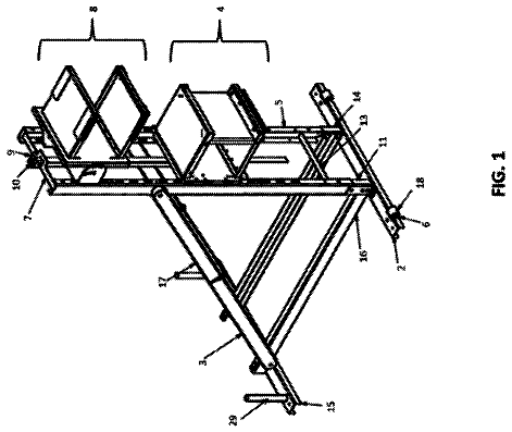
Sheet 1 of 6 from the published document. All sheets in the USPTO PDF
Embodiments of the present invention provide a device and a method of supporting a game controller such as a steering wheel without mounting it to a structure such as a desk or table. The game controller is instead supported on a number of extendable legs which are integral to the controller. In specific embodiments, a game controller with integral legs comprises a base which includes three telescoping legs which move outwardly to the extended position for providing support on the floor in front on the user's seat.
Many garners wish to use a steering wheel to control vehicles in their video games. This increases the level of immersion in the game by simulating the way vehicles are controlled in the real world. It also offers an increased level of control vs. an analog joystick since it has a much greater range of motion. Since the gaming boom of the 1980's many steering wheel controller designs have been introduced. Manufacturing a controller in the shape of a standard steering wheel is simple, however physically mounting the wheel in a way that is easy for the average home user has been a problem for as long as steering wheel controller designs have existed. In fact, the need to solidly mount the steering wheel to something, has been the major driver of different designs of steering wheel controllers. Most designs of the past have been designed to sit on a table top surface, for example <U.S. Pat.
1 of 6 drawing sheets so far from the published document, cropped to the drawing. Every sheet is in the USPTO PDF.
What the patent claimed, word for word. All of it is now free to use.
None.
None.
None.
This invention relates to video game controllers and specifically to ones shaped like steering wheels used for vehicle simulation video games.
Many garners wish to use a steering wheel to control vehicles in their video games. This increases the level of immersion in the game by simulating the way vehicles are controlled in the real world. It also offers an increased level of control vs. an analog joystick since it has a much greater range of motion. Since the gaming boom of the 1980's many steering wheel controller designs have been introduced. Manufacturing a controller in the shape of a standard steering wheel is simple, however physically mounting the wheel in a way that is easy for the average home user has been a problem for as long as steering wheel controller designs have existed. In fact, the need to solidly mount the steering wheel to something, has been the major driver of different designs of steering wheel controllers.
Most designs of the past have been designed to sit on a table top surface, for example <U.S. Pat. No. 8,920,240B2>. This design works if there is a table of the correct height available, but could involve moving furniture or in the worst case purchasing new furniture, which is not ideal Various table top mounting strategies like suction cups, rubber feet, and clamps have been commonly used.
Some designs like <US Pat. No. US20030067111A1> have also been designed to sit on a user's own lap. This is not particularly stable or ergonomic. It also limits how force-feedback motors can be used since the torque generated on the wheel can lift the base into the air while also transmitting all of that force into the user's legs.
With the recent popularity of accelerometer-based controllers, some console games now support holding up the controller in the air and rotating it with no physical connection to any base. In some cases, plastic shells are available to make the controller Into the shape of a wheel <U.S. Pat. No. 8,550,915 B2>. This is more of a compromise than a perfect solution, since it lacks any rotational feedback (relying on vibrational feedback only) and also the button layout of a controller shell system is not the same as it is on “professional” purpose-built wheels which are made to simulate vehicles accurately.
To illustrate what an issue mounting has been, there are even examples of purpose-built pieces of furniture that can have steering wheel kits mounted onto them. These are meant for people who have no suitable furniture for mounting their professional steering wheel. Sometimes this special mounting furniture is more expensive than the controller that mounts to it, making the complete video game controller assembly many times more expensive that it needs to be.
Embodiments of the present invention provide a device and a method of supporting a game controller such as a steering wheel without mounting it to furniture such as a desk or a table. An improved game controller has integrated telescoping legs and a means to be disassembled into subunits for storage and transport. The base portion is designed to stand on the floor with no additional support requirements.
Accordingly several advantages are to provide a stable platform for a steering wheel video game controller which is inexpensive, lightweight, and able to be stored in a small space.
FIG. 1 —Is a steering wheel controller with Integral legs in the operating position
FIG. 2 —Is a detail drawing of the steering wheel front, showing one possible embodiment of buttons on the front face
FIG. 3 —Is a side-view of how the steering wheel controller would be positioned relative to a human sitting in a seat
FIG. 4A , FIG. 4B , and FIG. 4C show how the base can be stowed in a compact form
FIG. 4A —Shows how the wheel portion can be removed from the base portion, and shows the telescoping legs in a stowed position
FIG. 4B —Shows the base components in the operational position, as well as the stowed position (dotted lines) but without the legs being folded
FIG. 4C —Shows the fully stowed configuration, including the legs being folded DESCRIPTION
FIG. 1 shows one possible embodiment of a complete steering wheel controller assembly with integral legs. The steering wheel ( 10 ) is attached mechanically to a drive assembly ( 11 ) which In some embodiments may be a brushless DC motor (BLOC) with a gear ratio reduction. The steering wheel and drive assembly may be attached together with a quick-release clamping mechanism to allow it to be disassembled. In an embodiment the drive assembly also may be detached from the base portion by means of a hand screw.
Legs ( 12 ) are symmetrically fixed to a center node ( 14 ) and able to pivot radially about this attachment point on hinges ( 15 ). In some embodiments, the legs ( 12 ) can telescope in order to change the height of the steering wheel ( 10 ), or to stow the controller for storage. The desired adjustment is fixed via clamps ( 13 ). The steering column ( 16 ) portion which is attached to the drive assembly ( 11 ) on one end is fixed to the center node ( 14 ) on the other hand. The steering column is adjustable in length by means of a clamp ( 17 ) and also the vertical angle can be adjusted by means of another clamp ( 18 ).
FIG. 2 shows a front view of one embodiment of a steering wheel ( 10 ). A number of buttons ( 20 ) are located on the front and/or back of the steering wheel in order to control functions of the video game other than steering. Some of the buttons may control functions of the game controller itself such as force feedback intensity. A display ( 21 ) may be used to provide information about the configuration of the steering wheel controller, such as force feedback intensity.
FIG. 3 shows a side view of the steering wheel ( 10 ) being held by a user ( 30 ) with their hands ( 32 ) while sitting in a seat ( 31 ). The steering wheel drive unit ( 11 ) is controlled by an electronic control circuit ( 34 ) which has a means to convert the physical angle of the steering wheel into commands which are sent on to a gaming device ( 36 ) over a connection such a physical wire or wireless radio ( 35 ). In some embodiments there is also means to send force-feedback information from the gaming console to the drive unit. The electronic control circuit ( 34 ) may be positioned anywhere relative to the drive unit ( 11 ). In one embodiment it is bolted to the side of the drive unit. Pedals ( 33 ) to may also be attached to the control circuitry to simulate the pedals within a vehicle.
FIG. 4A shows how the drive assembly is a separate unit which can be locked onto the base portion or removed for storage. It also shows the legs in the stowed position.
FIG. 4B shows the base components in the operational position, as well as the stowed position (dotted lines) but without the legs being folded
FIG. 4C shows the fully stowed configuration, including the legs being folded.
In order to provide even greater stability, if required, a weight may be added to the base subunit ( 40 ). In some embodiments this could be a bottle of water or lag of sand that attaches to the center node ( 14 ), however it could be any material that is heavy and it may attach anywhere.
In accordance an aspect of the invention, a method of supporting a game controller comprises attaching a stable base which is comprised of a center attachment node ( 14 ) with legs ( 12 )
In some embodiments, said method further comprises providing integrated legs attached to a central node which can be telescoped and/or folded in order to save space when not in use.
The method further comprises the ability to add an additional weight to the base portion to provide even greater stability if desired. The weight may comprise but is in no way limited to: a bag or bottle of heavy material such as sand, water, iron or lead.
When not in use, the steering wheel controller with integral legs may be stored away in a compact disassembled configuration. FIG. 4B shows the base portion ( 40 ) being collapsed, and FIG. 4C shows the packed configuration of the base portion. To operate the steering wheel controller, it is first assembled into the operating configuration. The steering wheel ( 10 ) and drive unit ( 11 ) are attached via clamps or hand screws to each other and to the base portion. The height and angle is adjusted using the clamps ( 13 , 17 , 18 ), so that the wheel ( 10 ) is at a comfortable position for the user. The operating configuration is depicted in FIG. 3 .
The electronic control circuit ( 34 ) is attached to a gaming device ( 36 ) electronically via a wire or wirelessly ( 35 ). and communicates electronically with the console, appearing as a controller which can be used to control games, in particular vehicle simulation and racing games. The drive assembly ( 11 ) has position feedback which is read by the control circuit ( 34 ) and send to the gaming device ( 36 ). Force feedback in the form of a rotational force on the steering wheel may be received from the game or it may be generated automatically by the control unit.
About 1,653 words. The USPTO PDF has it with every drawing.
Fees are due 3.5, 7.5 and 11.5 years after grant. This patent expired on November 23, 2025, so the fee marked "not paid" was the one that went unpaid.
Steering wheel control device with integral legs
Filed Jul 2020 · granted Nov 2021Earlier publications, parents and continuations. None of them can still be enforced, or this patent would not be listed.
Prior art cited by the examiner or applicant. Useful when you check your own idea for novelty.
Everything on this page comes from the documents linked above.