 Lapsed, fee not paid7 drawings
Sports & Fitness · US 11,257,243 B2
Camera-scored paper targets
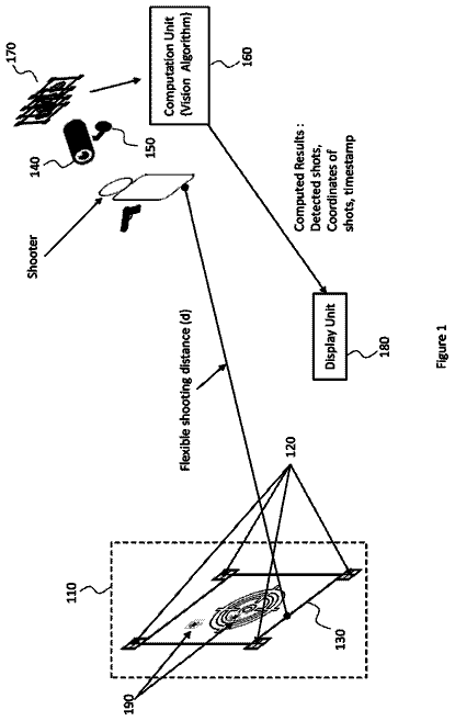
Paper targets printed with markers and barcodes so a camera can find the target and score every shot automatically.
US 11,135,463 B2 · Title as filed: Motor-driven variable weight exercise device with modular chassis body · Inventors: Rindfleisch; Randy Royce
Sheet 1 of 19 from the published document. All sheets in the USPTO PDF
A motor drives a carriage along a track to create variable resistance, replacing a stack of plates.
The invention herein relates to a variable weight exercise machine comprising a motor driven carriage assembly that moves along a linear path creating a variable resistant force against which the user exerts an opposite force. The chassis body and frame of said device may be positioned horizontally or vertically, and having a design that can be modularly configured in coordination with accessory elements to achieve a variety of concentric or eccentric exercise movements.
The first 3 of 19 drawing sheets from the published document, cropped to the drawing. Every sheet is in the USPTO PDF.
Independent claims and the claims that build on them, read from each claim's text.
What the patent claimed, word for word. All of it is now free to use.
Not applicable.
Not applicable.
This application is a continuation-in-part utility patent application claiming benefit of priority to and incorporating by reference in full the nonprovisional patent application Ser. No. 16/394,617, filed Apr. 25, 2019, in accordance with 35 U.S.C. § 119.
A portion of the disclosure of this patent document contains material that is subject to copyright protection. The copyright owner has no objection to the facsimile reproduction by anyone of the patent document or patent disclosure as it appears in the Patent and Trademark office, patent file or records, but otherwise reserves all copyright rights whatsoever. BACKGROUND OF THE INVENTION Field of the Invention
The present inventive subject matter relates to a device, method, and system for a variable exercise machine having a variable linear carriage held within a unitary chassis body and frame. Background
Portable exercise machines of the existing art have traditionally been designed with individual methods of exercise in mind. In the realm of concentric and eccentric exercises by way of weight machines, such devices have been designed for purchase or use among a commercial market or individual retail market. In the commercial realm, for example private health clubs where machinery is shared by a community of users, it had been preferable for each machine to have limited but defined purpose and design. It is not uncommon in these shared environments to find a variety of machines, each for a specialized method of exercise. The diversity and plurality of exercise options allow users to share equipment interchangeably without monopolizing space for too long. Machines or devices in the commercial context tend to be larger and heavier as well in order to sustain long term and extensive usage by many different people. The interest to sustain extensive long-term heavy usage in the commercial setting directs design towards machinery with heavier gauge and limited configurations.
Few weight machines have been designed with an equivalent durability for the individual retail market. In part, this is due to the fact that product distribution at the individual retail level is affected by product weight and size. Lighter weight designs are preferred simply to enable sales and distribution within the market. Slimness in design is also another preferred feature to accommodate spatial limitations of standard residential homes. The size and weight limitations of personal gym equipment often make them less durable for the desired level of exercise sought by the user. Dimensional and weight restrictions further make it difficult to achieve adjustable configurations among at home exercise machines.
U.S. Pat. Nos. 8,388,499 and 8,105,206 disclose two variable weight exercise machines containing a carriage moved along a linear path by screw mechanism that is motor driven. These devices are designed primarily for commercial use. They cannot be reconfigured and are limited in modes of exercise. U.S. Pat. No. 7,892,159 discloses a device having a central screw element attached to a motor drive system with parallel support rails for transport of a device along a linear path. Similarly, this device is non-adjustable in its configuration and provides a very slim design that may not safely or effectively endure extensive usage even in a home environment.
There remains a need in the art for a weight machine that can be accessible to a residential market by offer of a lighter weight frame (compared to commercial machines) yet having the stability and durability of a commercial machine, but offering a variety of exercise modes and variable weight challenges all within a single frame system.
The inventor herein has developed a new form of a variable weight exercise machine comprising a motor driven carriage assembly that moves along a linear path creating a variable resistant force against which the user exerts an opposite force. From the broadest context, the device comprising a unitary chassis body and frame containing a motor driven linear actuator capable of moving between variable locations along its linear path. Said motor driven linear actuator system having a carriage element thereon that is connectable to a plurality of elements that extend beyond the chassis body, interacting with the user. The chassis body and frame having a design that can be modularly configured in coordination with said carriage element, enabling a plurality of horizontal, vertical, or angular concentric or eccentric exercise movements. The material composition of said frame and extension elements of this invention should comprise durable hard material such as metal including without limitations, steel or aluminum, which can withstand the force of the user against the motorized linear actuator.
General Description of the Device
The various embodiments that is contemplated within the scope of this invention do have several component features in common. To begin, the exercise sought to be achieved by this invention is concentric and eccentric muscle action against a variable forward or rearward force. The variable forward and rearward force, which in traditional machines comprise tangible heavy weights of metal material, is instead created by a mechanical source within this invention. A motorized linear actuator system is held within a chassis frame that allows for coordination of a variety of exercise options therefrom. Additional attachments and accessories are contemplated within the scope of this invention which further maximizes or expands the variety of exercise options and directional motions achievable by the core features of this invention. The core feature of this invention mainly comprising a motorized linear actuator system held within an enabling chassis frame and positionable relative to a variety of attachments and accessories. The chassis frame and actuator system may be positioned vertically or horizontally to achieve any choice type of exercise. The system in its entirety is meant to be modular in nature. Modularity of this device would refer to a variety of achievable modular design which enables a variety of exercise options by those such designs. Modularity of this inventive device and system comprising the ability of the chassis frame (which holds the linear actuator system) to be detachably connected to the various accessories, attachments, subframe components by manner of pin connection. The various components of this invention have strategically placed perforations through opposing sides of their surfaces (front, rear, first and second sides, top and bottom) to allow for interconnection of components at strategic locations by sleeving pins snuggly therethrough, holding multiple components together in sturdy secure manner. The pins may serve a variety of roles beyond providing sturdy interconnection. In some cases, the pins may extend further outward to provide a location of leverage. The leverage may serve use for the user's body (i.e. a foot rest) or for enabling certain functions of an attached accessory (i.e. forming part of a pully system, etc.).
The motorized linear actuator system of this invention comprising a motor and a threaded linear screw drive to create both forward or rearward force. The motorized linear actuator system is securely held internally within the chassis frame at its either end, but preferably the end that is positioned closest to the ground surface when the chassis frame is seated in a vertical position. Depending on whether the chassis is in a vertical or horizontal position, the forward and rearward force within the chassis may be expressed in vertical up and down force or horizontal forward and backwards force. Since this is a mechanically driven force, it will nearly overpower the user in every case. As such, the quality of exercise experienced by the user would depend on how long the user can endure against the movement of the actuator by the user's opposing action.
An alternative embodiment of the motorized linear actuator system may comprise a motor drive attached to one or more rotating circular belts, each said belt of said one or more rotating circular belts rotatable along the length of said chassis frame, each traveling along a guide track (alternatively referable as a guide channel) along either side of said chassis frame in parallel manner. Said belts in this case is preferably a durable material able to withstand the force exerted thereon, such as metal chain.
Alternatively, said motorized linear actuator system drive system may comprise one or more threaded screw drives, said one or more threaded screw drives held within a guide channel or guide track either centrally along the chassis frame or along either side of said chassis frame. The directional movement of each threaded screw drive (clockwise versus counter-clockwise rotation) is determined by a motorized drive system. If it is intended for two or more threaded screw drives to rotate in opposing directions, then each said directional movement will require its own separate motor drive connection to control each separate directional movement.
Yet another embodiment of the invention comprising a single threaded screw drive centrally positioned along the length of said chassis frame, wherein said threaded screw drive is connected to a carriage thereon which travels along the length of said chassis frame. Said carriage may further be supported on either its right or left sides, or both sides, with rollers that traverse two opposing parallel guide tracks along the length of said chassis frame. The carriage element of this invention as described herein comprises a platform that attaches directly to the threaded screw drive, protruding beyond the actuator system and external to the chassis frame, forming the portion of the device that interacts with the user either directly (i.e. a seat) or by means of an attached accessory (i.e. chain extension, handle, or foot peddle).
The carriage element of this device provides a platform that is attachable to additional tools or platforms which interfaces directly with the user. The tools may comprise without limitations wires, chains, or additional frame elements, all of which are intended to be moved and driven by said drive system and carriage element. The external platform attachable to said carriage element may comprise a seat that carries a user seated thereon. Alternatively, the external platform may comprise a vertical frame extendable from said carriage above said chassis frame such that said vertical frame may be moved to variable locations along the length of said horizontal chassis frame. Said vertical frame extension may comprise a vertically positioned panel or plate having a planar surface (also referable herein as a vertical panel). The user would be seated on a stationary (nonmoving) platform while exerting force against said planar surface of said vertically positioned plate which moves along the length of said chassis frame.
Said carriage element may further provide connection means that allow a length of flexible and durable exercise strap to be attached to said carriage element, the farther portion of said strap looping through or around a leveraging mean (i.e. an eye hook, J hook, cross-bar, etc.) such that when the strap is pulled by said carriage at its first end, said strap is leveraged against said leveraging means and pulls away from the user seated on an external platform (i.e. seat) that is also attached to and above said carriage element. The leveraging means may in fact be positioned at any location along the chassis frame or extensions therefrom to allow for variable angular bodily exercises and movements by pulling against a strap element. Said leveraging means may comprise perforations cut through said chassis frame wherein said straps would loop therethrough. Alternatively, said leveraging means may comprise looping means (i.e. eye hooks or J hooks) that are either permanently attached or removably attachable to any location on said chassis frame or said extensions therefrom. Said leveraging means may also comprise cross-bars that extend from said chassis frame. Said cross-bars may be permanently attached or alternatively be created by sleeving a thick diameter pin through matching perforations of said chassis frame where in the pins extend outward on either right and left sides (alternatively referable as first and second sides) of the chassis frame to provide sufficient surface area for such leverage. Said leveraging means importantly must be securely connectable to said chassis frame or extensions therefrom to not dislodge against an exerted force, may have loose straps sleeve therethrough or therearound, and allows for sliding movement of said straps therethrough or therearound. The external tools, external platforms, perforations, and other such leveraging means are removably attachable to said carriage to enable variable exercise options thereon, for ease of storage, and for ease in packaging for improved transport.
A more specific embodiment of the invention provides for a variable load resistant exercise machine that is enabled by a motor-driven linear load transfer system contained within a singular chassis frame and body that is capable of modular configurations. The linear load transfer system comprising a linear actuator such as a threaded screw drive mechanism connected to a motor drive. Said threaded screw drive being centrally disposed within said chassis along its length. Said threaded screw drive further connected to a chassis element that traverses the length of said threaded screw drive in variable manner in terms of speed and locational position. Said carriage element further stabilized on either side by rollers or wheels that traverse along parallel guide tracks along the length of said chassis to its right and left sides. By this invention, the chassis comprise a long horizontal frame that is lower to the ground and provides a wider and lower center of gravity for the user seated thereon. The two parallel guide tracks along the length and sides of the chassis helps to balance and stabilize the shifting weight of a user seated thereon. The parallel guide tracks provide stable support for directional movement of the carriage along the length of the body and spreads the weight of the device and user across a wider surface area. The motor drive and linear transfer element may be manually, digitally, or electronically controllable by direct or remote communication through sensing elements. A digital panel containing preconfigured software language is connectable to said device of this invention, receiving user related electrical input from said device that is translatable into performance data that is viewable and readable from said device panel. A typical load cell transducer may be used to translate the force experienced by the user into standard signal and readable data for this purpose. Alternatively, the force of the machine as experienced by the user may be measured directly from the motor drive by manner of mathematical calculations. The received electrical signal data from the load cell transducer would be digitally translated within the computer system of the device. While alternatively, the draw of force from the motor may be mathematically calculated by the computer system by preconfigured algorithmic means more directly (without need of a transducer element) based on the known qualities of the motor and its variable functions. This alternative manner of reading force is achievable by reading directly the draw of force from the motor because unlike any prior machine within the industry, the user according to this invention is directly engaging in exercise against the raw force of the motor. As such, a measure of the draw of force from the motor serves as reliable data on user exercise input and output. Said viewable digital panel is an optional feature to this invention and may be detachable for a more basic model of the device. Because the device operates by an electrical motor drive system, it is feasible to control the device by push button means either directly or remotely. Remote control may be achieved by any wireless digital, electrical, or radio signal system such as a key-fob device.
The body of this device having strategic perforations on its sides along its length to allow pin or cross-bar elements to be sleeved through at prescribed locations for additional user options. According to the summary and description of this invention, the term cross-bar element and pin are used interchangeably as being a metal rod that sleeves through perforations of the device, its subframe components, accessories, and any attachments. Both terms describe the effect of interconnecting the various components together with the potential of serving additional function such as leverage. At least one or more pin element is sleevable through the cross-section of said chassis to maintain structural integrity of the device. The pin element helps to prevent warping of the chassis frame, which otherwise would cause a loss of parallel positioning of said parallel guard rails and thus block linear transfer. The pin element may terminate in a fixed (i.e bolted) manner at the side surface of said chassis in flush manner or alternatively extend beyond the side surfaces of said chassis in removable manner, outward towards the external environment. By extending externally beyond the surface of said chassis, the user may utilize the extended portion of the pin element as leverage. The extended pin element may either serve as a leveraging means whereby straps may wrap therearound for a pulling exercise. It may alternatively serve as foot rest for the user, leveraging the user's lower body against opposing weights.
Additional pin elements may relate to a back rest element. Said back rest element being hingely attached to the top of said chassis and is able to toggle or swivel forwards and backwards, ultimately resting against the pin element. The side surfaces along the body of said chassis having strategically placed perforations would allow said pin element to be sleeved through a location either frontward or rearward of said back rest in either its forward or rearward position, creating a forward or rearward seating option on said chassis. When said pin element is removed away from the back-support element, the back-rest element would decline fully to a horizontal position overtop said chassis. Said back-rest element also allowing for detachable connection of cushion elements to be held thereon for comfortable use and seating. Said cushion elements may be detachably connectable to said back-rest element by hook and loop means or any other known sturdy and detachable methods of connection.
The device of this invention further providing handle elements. Said handle elements preferably comprising two parallel bars extending horizontally from said vertical frame extension from a right and left side towards the chassis frame. Said two parallel bars terminating with either a handle element. Said handle element may comprise a simple linear grip element (i.e. a vertically disposed round pole) or alternatively a circular ball-gripping element. Said linear gripping element would require a fisted grip therearound. Said ball-gripping element may comprise a smooth ball shaped component where it's top half circumference may be substantially or fully gripped by an adult hand. The round shape of a ball shaped grip component allows a controlled grip of the handle without a fisted hold. This is important to certain individuals who may suffer muscular or nerve damage in their hands. The rounded feature also allows for much easier repositioning of a hand grip during exercise by a sliding movement of the hand grip thereover.
Vertical & Horizontal Dual Axis Embodiment
Yet another embodiment of this invention that encompasses all of the above described features and embodiments provides for a pivotable chassis which may be pivoted between a horizontal position to and from a vertical position for dual axis exercise options. By this embodiment, a support frame is provided along the horizontal axis to provide leverage and connection to the chassis when it is rotated to a vertical position. The motor and drive components held within the chassis as described in the above general descriptions would preferably be positioned at a first end of this invention such that when the device is rotated upright in vertical manner, the motor and drive elements within the first end would be positioned furthest from the ground level. The second end of the chassis will serve as the point of rotation such that the chassis would be able to pivot from its horizontal position at the ground level to an upright vertical position by lifting and rotating the device within 90 degrees at its second end, the second end serving as the point of axis. The device may similarly be lowered to its horizontal position by rotating the device within 90 degrees downward at it the second end, serving as the pivot point. The mechanical components of the chassis are therefore held within that lower half of the chassis closest to the second end. The drive element, preferably a linear screw drive element, would be vertically positioned in linear manner such that by action of the motor will cause an upward and downward movement of attachments connected to said linear screw drive element in threaded manner.
The support frame of this alternative embodiment comprising a horizontal frame that is seated along the ground surface and connectable to the second end of the chassis at its first end. The connection between the first end of the support frame and the second end of the chassis comprising a detachable bridge (which serves as a gusset and referred interchangeably to as a gusset) having perforations therethrough such that the location of perforations on said gusset is in matching location to perforations along the second end of said chassis between its first and second (or right and left) sides and at matching ends of the first end of the support frame between its first and second (or right and left) sides as well. A heavy gauged linear pin, which comprises metal bar or rod, is sleeved through the matching holes of the gusset and chassis and at matching holes of the gusset and support frame to create a leverage between the support frame and the chassis. This leverage connection comprising a gusset connection as described at both first and second sides of the chassis and the support frame with a common linear bar (alternatively referred to as a pin) connection therethrough. The gusset pieces are in tangential relationship between the vertical axis of the chassis and the horizontal axis of the support frame.
The support frame comprising two lengths of parallel bars each in adjacent contact with the first and second sides of the second end of the vertically positioned chassis. The space between each said parallel bars of the support frame to have the same or substantially similar width of the chassis frame such that the second end of the chassis frame is snuggly seated therebetween. The length of this horizontal extension of the support frame by its parallel bars facing an exposed side of the chassis frame where the screw drive held therein may be connected to an accessory that extends outward towards a user who is positioned above the support frame either in seated or standing position. These two parallel bars extend further beyond the second end of the chassis frame to be in a perpendicular position from the vertically positioned chassis frame.
The parallel bars of the support frame are interconnected by pins that sleeve though matching perforations within the parallel bars. A first pin is sleeved though a first end of a first parallel bar, then through a perforation at the bottom end of a first gusset element, and through a matching perforation at the first end of a second parallel bar. A second pin is sleeved through matching perforations between the first parallel bar, the first and second sides of a first corner of the second end of the vertically positioned chassis, and through the second parallel bar. A third pin is sleeved through the matching perforations between the first parallel bar, the first and second ends of a second corner of the second end of the vertically positioned chassis, and through the second parallel bar. A fourth pin is sleeved through the matching perforations of the second end of said parallel bars. More pins may be added as needed for support or leverage.
The invention herein further providing accessory components that are removably detachable or adjacently positionable to enable a variety of exercises. According to the preferred embodiment of this invention, a detachable sub-frame component comprising two shorter parallel bars, each parallel bar being a mirror design of the other. Each parallel bar of said sub-frame component having a variety perpendicular extensions. The perpendicular extension may comprise a foot pedal or a leverage bar attached to its first end located closest to the chassis when positioned alongside the support frame. When each of the two sub-frame components are positioned at either side of the support frame, it forms support and leverage features for added variety to the user's exercise options. Other attachments may be interconnected between the short parallel bars of the sub-frame component and the support frame, such as a vertical handle comprising a stand-alone vertical bar positioned adjacently to either of said short parallel bars and connected in place by a pin. The vertical handle may be positioned at a variety of angles above the ground surface by resting its bottom end between a first and second pin where said first and second pin are angularly positioned relative to the other. According to a preferred embodiment herein, a detachable bench may be positioned over the support frame to enable stable seating and leveraged exercises.
Modular Frame System
Yet another aspect of the invention herein comprising the greater feature of its modular frame. The invention herein comprising a portable at-home multi-faceted exercise machine that enables a wide variety of vertical and horizontal concentric and eccentric weight exercises by an enabling modular feature. The enabling modular feature of this invention comprising a series of perforations located along the surface of the frame components, chassis, and accessory components. The perforations are strategically placed along the surface of each accessory component, frame components, and chassis, to be sleeved completely through at matching locations by pin elements to create an interconnection between them. The pin elements preferably comprising hard durable metal material of a preferred diameter to endure the amount of torque or weight that it must maintain during repetitive exercise. The pin elements may have a smooth surface along its length or alternatively be threaded for attachment of a threaded nut for enhanced security and sturdiness. The diameter of the pin element should be substantially the diameter of the particular perforation hole that it is intended to be sleeved through for a secure sturdy and tight connection. It is the intention that the connection of each pin with its respective various perforations be tight enough to not easily slide apart during use, to avoid rattling of the inventive device, and for the overall structural integrity of the entire device in its assembled form during use to be tightly connected. The various embodiments that falls within the scope of this invention is shown and described low in the detailed descriptions and within the drawings, but is not limited to what is presented herein but may include other embodiments not described but do otherwise exercise the broadest features and intentions of this invention.
Methods of Use
The device of this invention providing a variety of modular components which can either be repositioned or detachably connectable in different configurations for a variety of exercise movements. The preferred embodiment of this device may achieve the following variety of focused weight exercises: 1) chest exercises, 2) back exercises, 3) arm exercises, 4) shoulder exercises, 5) quadricep exercises, 6) hamstring exercises, 7) bicep exercises, 8) and tricep exercises. Specific types of exercise motions may comprise the following without limitations: 1) leg press, 2) row, 3) squat, 4) curl, 5) pull down, 6) chess press, 7) bench dip, 8) abdominal crunch. Other exercise motions not otherwise listed here are achievable by simple reconfiguration of the device herein. The detailed descriptions below together with the attached illustrations will provide examples of the various methods of exercise achievable by various modular arrangements of this invention according to its modular design.
FIG. 1 provides a right side perspective view of the invention according to a preferred embodiment as illustrated.
FIG. 2 provides a right side perspective view of the invention according to a preferred embodiment as illustrated.
FIG. 3 provides a partial top perspective view of the internal rear end portion of the invention according to a preferred embodiment of this invention.
FIG. 4 provides a partial top perspective view of the internal front end portion of the invention according to a preferred embodiment of this invention.
FIG. 5 provides a right side perspective view of the invention according to a preferred embodiment as illustrated.
FIG. 6 provides a right-side plan view of the invention according to a preferred embodiment as illustrated.
FIG. 7 provides a left-side plan view of the handle portion of the invention according to a preferred embodiment as illustrated.
FIGS. 8 a and 8 b provides a right-side plan view of the invention according to a preferred embodiment as illustrated.
FIGS. 9 a and 9 b provides a right-side plan view of the invention according to a preferred embodiment as illustrated.
FIGS. 10 a and 10 b provides a right-side plan view of the invention according to a preferred embodiment as illustrated.
FIGS. 11 a and 11 b provides a right-side plan view of the invention according to a preferred embodiment as illustrated.
FIGS. 12 a and 12 b provides a right-side plan view of the invention according to a preferred embodiment as illustrated.
FIGS. 13 a and 13 b provides a right-side plan view of the invention according to a preferred embodiment as illustrated.
The present invention is best understood by reference to the detailed figures and description set forth herein. Embodiments of the invention are discussed below with reference to the Figures. However, those skilled in the art will readily appreciate that the detailed description given herein with respect to these figures which is for explanatory purposes as the invention extends beyond these limited embodiments. It is to be understood that the present invention may be embodied in various forms. Therefore, specific details disclosed herein are not to be interpreted as limiting, but rather as a basis for the claims and as a representative basis for teaching one skilled in the art to employ the present invention in virtually any appropriately detailed system, structure or manner. For example, it should be appreciated that those skilled in the art will, in light of the teachings of the present invention, recognize a multiplicity of alternate and suitable approaches, depending upon the needs of the particular application, to implement the functionality of any given detail described herein, beyond the particular implementation choices in the following embodiments described and shown. That is, there are numerous modifications and variations of the invention that are too numerous to be listed but that all fit within the scope of the invention. Also, singular words should be read as plural and vice versa and masculine as feminine and vice versa, where appropriate, and alternative embodiments do not necessarily imply that the two are mutually exclusive.
It is to be understood that any exact measurements, dimensions or particular construction materials indicated herein are solely provided as examples of suitable configurations and are not intended to be limiting in any way. Depending on the needs of the particular application, those skilled in the art will readily recognize, in light of the following teachings, a multiplicity of suitable alternative implementation details.
The present invention will now be described in detail with reference to embodiments thereof as illustrated in the accompanying drawings.
The invention herein specifically comprising the following elements, as illustrated in part by the referenced figures. The illustrations and figures herein serve to explain certain aspects of the described invention and should not be read to limit the scope of this invention. Other embodiments will be understood to be within the scope of this invention according to the description provided herein.
The device of this invention according to a preferred embodiment as illustrated in FIGS. 1 through 4 , specifically as shown in FIGS. 1 and 2 , comprises the following elements: A hollow geometrically shaped body horizontally (also referred to as the chassis frame) 101 disposed and seatable on a ground surface, a rotatable resting element 102 , a vertical platform 103 , and optionally a digital panel 104 attached to a rotatable digital panel arm 105 . Said hollow geometrically shaped body or alternatively referenced as chassis frame or chassis body 101 having a front 106 , rear 107 , top 108 , bottom 109 , right 110 , and left side 111 surfaces. Said top 108 , bottom 109 , right 110 , and left 111 sides surfaces forming the length of the device which is longer than its said cross-sectional width, in total having a substantially rectangular shape. The length of said chassis frame may be any length but is preferably 6.5 feet long (78 inches) or alternatively a preferred length of under 8 feet long. The height of side surfaces may be up to 36 inches but is preferably 11 inches tall according to the preferred embodiment of this invention. Said front 106 , rear 107 , top 108 , bottom 109 , right 110 , and left 111 side surfaces having an external surface 112 facing the external environment and an internal surface facing the internal space within said hollow geometrically shaped body 101 . The width of said top 108 and bottom 109 surfaces may be up to 36 inches wide but is preferably 13 inches wide according to the preferred embodiment of this invention. Said hollow geometrically shaped body 101 , comprising said front 106 , rear 107 , top 108 , bottom 109 , right 110 , and left 111 side surfaces of this preferred embodiment comprising the chassis body (or alternatively referred to as the chassis frame) 101 of this invention.
Said rotatable resting element 102 comprising a planar panel 115 of substantially similar cross-sectional width as said top surface 108 of said chassis frame 101 and rearwardly disposed within the rear half along the length of said chassis frame 101 . Said planar panel 115 of said resting element 102 having a length that is greater than its width. Said length comprising a left 116 and right side 117 parallel to the left 111 and right 110 sides of said chassis frame. Said planar panel 115 terminating at a top 118 and bottom 119 side. Said top side 118 of said planar panel element 115 terminating beyond the rear end 107 of said chassis frame 101 while the bottom end 119 terminates within the rearward half of said top surface of said chassis frame 101 . A rotating mechanism comprising a bar 120 sleeved through perforations 121 along the left 111 and right 110 side surfaces of said chassis frame 101 . Said planar panel 115 rotatable along a vertical path over the top side surface 108 of said chassis frame 101 within a substantially 180 degrees rotation.
Said chassis frame according to a preferred embodiment of this invention according to FIGS. 1 and 2 having perforations therethrough between its right 110 and left 111 side surfaces in matching form, dimension, and design to each enable a narrow pipe or bar to snuggly fit or sleeve therethrough in straight perpendicular manner between said right 110 and left 111 side surfaces. The perforations may comprise any pattern but should sufficiently match and mirror each other between said right 110 and left 111 sides to enable any pin element to fit therethrough in substantially horizontal fashion, whether or not perpendicular in nature. The additional purpose of having perforations throughout the chassis frame is to remove excess weight without harming the structural integrity and sturdiness of the frame. This is highly beneficial for purposes of achieving lower cost in shipping and distribution of the inventive device to customers.
The purpose for fitting a bar through the chassis frame 101 between said left 111 and right 110 side surfaces is to create additional leverage, repositioning of parts, or introduction of additional tool elements. For example, as shown in FIGS. 1 and 2 , pin elements 120 located along the bottom rearward half of said chassis frame serves to block rotation of said resting element 102 , allowing the resting element 102 to maintain a substantially vertical position. Depending on the position of said pin element 120 , the resting element 102 may be disposed in a forward direction or rearward direction. A forwardly angled vertical position of said resting element 102 creates a back rest for the user who may be seated facing rearward on said chassis frame 101 . Likewise, a rearwardly angled vertical position of said resting element 102 creates a back rest for the user who may be seated facing forward on said chassis frame 101 . According to a preferred embodiment of this invention, a radially disposed series 122 or plurality of perforations are provided directly below the bottom side of said planar panel along the right 110 and left 111 side surfaces of said chassis, allowing for angular adjustment of the vertical positioning of said planar panel 115 . The diameter or length of each perforation of said radially disposed series 122 of perforation is preferably 0.375 inches, but may be any greater or lesser diameter to achieve its intended purpose. Larger circular perforations 123 are preferably up to 1.76 inches in diameter. Even further, perforations may comprise any geometric shape and may have a length or diameter up to the width, height, or length of said chassis body to serve any variety of functional or aesthetic purposes as described herein.
The internal space of said chassis frame according to FIGS. 3 and 4 of the preferred embodiment containing the following elements: A motor drive 401 , a linear actuator 402 which may comprise a threaded screw element, two parallel guide tracks 403 , a carriage 301 seated over said two parallel guide tracks 403 . Said linear actuator 402 comprising a length of threaded screw with any preferred length between one
The description continues in the full USPTO document.
Fees are due 3.5, 7.5 and 11.5 years after grant. This patent expired on October 5, 2025, so the fee marked "not paid" was the one that went unpaid.
MOTOR-DRIVEN VARIABLE WEIGHT EXERCISE DEVICE WITH MODULAR CHASSIS BODY
Filed Apr 2020 · published Oct 2020Motor-driven variable weight exercise device with modular chassis body
Filed Apr 2020 · granted Oct 2021Earlier publications, parents and continuations. None of them can still be enforced, or this patent would not be listed.
Prior art cited by the examiner or applicant. Useful when you check your own idea for novelty.
Names, summaries, modern angles and build ratings are Patent Yard's editorial notes. Everything else on this page comes from the documents linked above.