 Lapsed, fee not paid7 drawings
Sports & Fitness · US 11,257,243 B2
Camera-scored paper targets
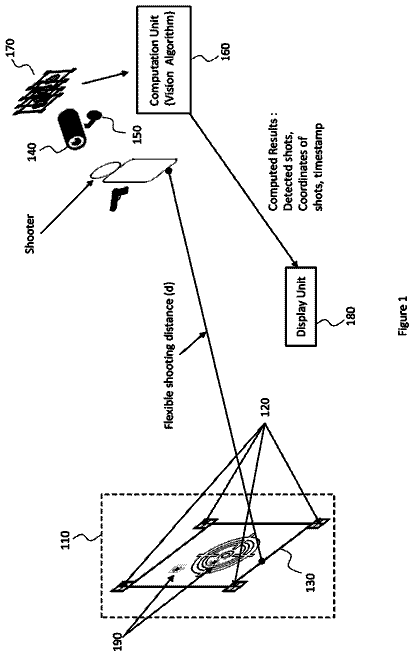
Paper targets printed with markers and barcodes so a camera can find the target and score every shot automatically.
US 11,110,340 B1 · Title as filed: Modular assembly and method of use · Inventors: Emricson; Nic
Sheet 1 of 15 from the published document. All sheets in the USPTO PDF
A set of pieces that assemble into many 3D battle maps for tabletop role-playing games.
This invention relates to a modular gaming map, where a set of components can be assembled into a variety of configurations to create a three-dimensional map as a supplement for simulated battles and role-playing games, and compatible with industry standard figurines and models.
The first 3 of 15 drawing sheets from the published document, cropped to the drawing. Every sheet is in the USPTO PDF.
Independent claims and the claims that build on them, read from each claim's text.
What the patent claimed, word for word. All of it is now free to use.
Non-limiting and non-exhaustive examples of several of the various embodiments of the present invention are described with references to the following figures, and reference numbers refer to the same features throughout the various views and embodiments unless otherwise specified.
FIG. 1 is a top perspective illustration of an embodiment of a modular assembly, if seen assembled on a flat surface, showing a possible variety of modules with various vertical structures and elevators to create a potential configuration of an embodiment of the invention.
FIG. 2 is a bottom perspective illustration of an embodiment of a modular assembly similar to FIG. 1 , showing a possible variety of modules connected by couplers and utilizing various vertical structures and elevators to create a possible configuration of an embodiment of the invention.
FIG. 3 is a bottom perspective illustration of a possible embodiment of two, four-sided modules in a position on the adjacent edge sides of the modules with a possible embodiment of a coupler fit into two adjacent coupler pockets in the modules, and a dashed-line indicating the cross-section line of FIG. 4 .
FIG. 4 is a cross section of a possible embodiment of the invention showing the tapered coupler fit by the coupler and coupler pockets and coupler notches of the modules, similar to that shown in FIG. 3 .
FIG. 5 is a bottom perspective view of an embodiment of a module showing the second side of the module, including mounting holes, coupler notch, and lug pockets.
FIG. 6 is a top perspective view of a possible embodiment of a modular similar to the embodiment in FIG. 5 , showing the first side of the module with mounting holes on the top surface, and an edge side of the module with a coupler notch.
FIG. 7 is a bottom view of a possible embodiment of a module, showing the second side of the module, including coupler pockets, lug pockets, and
FIG. 8 is one side view of a possible embodiment of the coupler in the invention showing a H-shaped coupler, with material saving spaces, two substantially oblong shaped coupler heads, and a coupler neck.
FIG. 9 is an opposite side perspective view of a possible embodiment of the coupler in the invention similar to FIG. 8 , showing a H-shaped coupler, including two coupler heads and a coupler neck.
FIG. 10 is a bottom perspective view of a possible embodiment of the module of the invention that contains three coupler pockets on each edge side, as a larger module as compared to FIG. 5 if used together in a modular assembly.
FIG. 11 is a top perspective view of a possible embodiment of the module of the invention similar to FIG. 10 , showing the top surface of the first side and two edge sides with three coupler notches on each edge side.
FIG. 12 is a side view of a possible embodiment of the module of the invention similar to FIG. 11 , showing an edge side of the module with three coupler notches, the module oriented to have the top surface/first side to be towards the bottom of the page.
FIG. 13 is a top perspective view of a possible embodiment of the module of the invention showing a textured design of the top surface of the first side of a module with six edge sides and one coupler notch on each edge side.
FIG. 14 is a bottom perspective view of a possible embodiment of the module of the invention similar to FIG. 13 , showing the second side of a module with six edge sides and one coupler pocket on each edge side.
FIG. 15 is a side view of a possible embodiment of the module of the invention similar to FIG. 14 , showing a textured design of the top surface of the first side of module with three edge sides and one coupler notch on each edge side.
FIG. 16 is a top-side perspective view of a possible embodiment of the module of the invention showing a module with three sides.
FIG. 17 is a bottom view of a possible embodiment of the module of the invention, showing the second side of a module with three edge sides and two coupler pockets. Only two of the edge sides have coupler notches and coupler pockets. It also shows the lug pockets, coupler pockets, and coupler notches on the edge sides of the module.
FIG. 18 is a bottom perspective view of a possible embodiment of the module of the invention, showing the second side of a module with three edge sides.
FIG. 19 is a top perspective view of an embodiment of the module of the invention, showing the top surface on the first side of a module with three edge sides and one edge side has no coupler notch.
FIG. 20 is a bottom view of an embodiment of the module of the invention, showing the second side of the module with three edge sides. Two of the edge sides have two coupler pockets each, and one side has no coupler pockets. It also shows the coupler notches on the edge sides, tapered coupler pockets, and lug pockets.
FIG. 21 is a bottom perspective view of an embodiment of the module of the invention, showing the second side of a module with three edge sides similar to the embodiment of FIG. 4 .
FIG. 22 is a front perspective view of an embodiment of the stair assembly of the invention, which is a vertical structure, including the stair stringers, tread connectors, open stair riser, and the tuck-in space between two tread connectors, which can accommodate a gaming base edge.
FIG. 23 is an exploded view of an embodiment of the stair assembly, showing the relationship between different parts of the stair assembly, including stair stringers and tread connectors.
FIG. 24 is a front perspective view of an embodiment of the elevator of the invention, showing the elevator's lugs whereby a module could attach the lug to its lug pockets to create an elevated level.
FIG. 25 is a block diagram, illustrating more basic embodiments of a modular assembly.
FIG. 26 is a top perspective view of various embodiments of a coupler neck relative to the number of coupler heads.
Corresponding reference characters indicate corresponding components throughout the several views of the drawings. Skilled artisans will appreciate that elements in the figures are illustrated for simplicity and clarity and have not necessarily been drawn to scale. Also, common but well-understood elements that are useful or necessary in a commercially feasible embodiment are often not depicted in order to facilitate a less obstructed view of these various embodiments. Common and easily configurable/variable. Additionally, the disclosed architecture is sufficiently configurable, such that it may be utilized in ways other than what is shown.
In this Specification, which includes the figures, claims, and this detailed description, reference is made to particular and possible features of the embodiments of the invention, including method steps. These particular and possible features are intended to include all possible combinations of such features, without exclusivity. For instance, where a feature is disclosed in a specific embodiment or claim, that feature can also be used, to the extent possible, in combination with and/or in the context of other aspects and embodiments of the invention, and in the invention generally. Additionally, the disclosed architecture is sufficiently configurable, such that it may be utilized in ways other than what is shown.
The purpose of the Abstract of this Specification is to enable the U.S. Patent and Trademark Office and the public generally, and especially the scientists, engineers and practitioners of the art who are not familiar with patent or legal terms or phrasing, to determine quickly from a cursory inspection the nature and essence of the technical disclosure of the application. The Abstract is not intended to be limiting as to the scope of the invention in any way.
In the following description, numerous specific details are given in order to provide a thorough understanding of the present embodiments. It will be apparent, however, to one having ordinary skill in the art, that the specific detail need not be employed to practice the present embodiments. On other instances, well-known materials or methods have not been described in detail in order to avoid obscuring the present embodiments. When limitations are intended in this Specification, they are made with expressly limiting or exhaustive language.
Reference throughout this Specification to “one embodiment”, “an embodiment”, “one example” or “an example” means that a particular feature, structure, or characteristic described in connection with the embodiment or example is included in at least one embodiment of the present embodiments. Thus, appearances of the phrases “in one embodiment”, “according to an embodiment”, “in an embodiment”, “one example”, “for example”, “an example”, or the like, in various places throughout this Specification are not necessarily all referring to the same embodiment or example. Furthermore, the particular features, structures, or characteristics may be combined in any suitable combinations and/or sub-combinations in one or more embodiments or examples.
The terms “comprises”, “comprising”, “includes”, “including”, “has”, “having”, “could”, “could have” or their grammatical equivalents, are used in this Specification to mean that other features, components, materials, steps, etc. are optionally present as a non-exclusive inclusion. For instance, a device “comprising” (or “which comprises”) components A, B, and C can contain only components A, B, and C, or can contain not only components A, B, and C but also one or more other components. For example, a method comprising two or more defined steps can be carried out in any order or simultaneously, unless the context excludes that possibility; and the method can include one or more other steps which are carried out before any of the defined steps, between two of the defined steps, or after all the defined steps, unless the context excludes that possibility.
Further, unless expressly stated to the contrary, “or” refers to an inclusive or and not to an exclusive or. For example, An embodiment could have optional features A, B, or C, so the embodiment could be satisfied with A in one instance, with B in another instance, and with C in a third instance, and probably with AB, AC, BC, or ABC if the context of features does not exclude that possibility.
Examples or illustrations given are not to be regarded in any way as restrictions on, limits to, or express definitions of any term or terms with which they are utilized. Instead, these examples or illustrations are to be regarded as being described with respect to one particular embodiment and as being illustrative only. Those of ordinary skill in the art will appreciate that any term or terms with which these example or illustrations are utilized will encompass other embodiments, which may or may not be given in this Specification, and all such embodiments are intended to be included within the scope of that term or terms. Language designating such nonlimiting examples and illustrations includes, but is not limited to “for example”, “for instance”, “etc.”, “or otherwise”, and “in one embodiment.”
The phrase “at least” followed by a number is used to denote the start of a range beginning with that number, which may or may not be a range having an upper limit, depending on the variable defined. For instance, “at least 1” means 1 or more.
In this specification, “a” and “an” and similar phrases are to be interpreted as “at least one” and “one or more.” In this specification, the term “may” or “can be” or “could be” is to be interpreted as “may, for example.” In other words, the term “may” is indicative that the phrase following the term “may” is an example of one of a multitude of suitable possibilities that may, or may not, be employed to one or more of the various embodiments.
The phrase “a plurality of” followed by a feature, component, or structure is used to mean more than one, specifically including a great many, relative to the context of the component. For example, “a plurality of modules” means more than one, and specifically includes more than a few and at least one embodiment of the invention includes hundreds of modules on one modular assembly.
It is the applicant's intent that only claims that include the express language “means for” or “step for” be interpreted under 35 U.S.C. § 112. Claims that do not expressly include the phrase “means for” or “step for” are not to be interpreted under 35 U.S.C. § 112.
The disclosure of this patent document incorporates material which is subject to copyright protection. The copyright owner has no objection to the facsimile reproduction by anyone of the patent document or the patent disclosure, as it appears in the Patent and Trademark Office patent file or records, for the limited purpose required by law, but otherwise reserves all copyright rights whatsoever.
FIG. 1 is a top perspective illustration of an embodiment of a modular assembly 300 in the form of a possible configuration according to one embodiment, where at least two modules 200 are arranged next to each other. Each of these modules 200 has a first side 210 with a top surface 220 (no textured surfaces have been shown in this embodiment for simplicity) and at least three edge sides 240 . Some edge sides include coupler notches 242 in certain embodiments. It also shows a variety of vertical structures 320 which can be added to the modules 200 , to create rooms with walls, transitions to raised planes of play, and other game related structures within the modular assembly 300 , like a door 322 , a wall 324 , and a stair assembly 326 . Furthermore, FIG. 1 illustrates a possible embodiment of a raised plane of some of the modules 200 by elevators 310 following a stair assembly 326 , which is a type of vertical structure 320 . Having a few modules of a raised plane can add depth and variety to a map assembly, and the enjoyment of a user.
FIG. 2 is a bottom perspective illustration of an embodiment a modular assembly 300 , similar to FIG. 1 , but showing the second side 230 of the modules 200 , adjoined together by couplers 110 that are substantially “H”-shaped, at the coupler pockets 234 . It also shows the lug pockets 232 on the bottom of the corner modules 200 and elevators 310 creating a raised plane of connected modules 200 .
FIG. 3 is a bottom perspective illustration of a possible embodiment of two modules 200 , showing the second side 230 of two modules 200 are adjoined together by substantially “H”-shaped coupler 110 with substantially oblong-shaped coupler heads 120 connected by a single coupler neck 140 . The embodied example of FIG. 3 shows the two substantially oblong-shaped coupler head 120 of the coupler 130 fit into the coupler pocket 234 of two adjacent modules 200 , while the coupler neck 140 fits into the coupler notches 242 in the edge sides of the modules 200 . In this embodiment, there is also lug pockets 232 on the corners of each module 200 . The top surface 220 of the first side 210 can be seen behind the second side 230 of the module 200 . The arrowed and dashed line indicated as “4” through one of the coupler heads fit into a coupler pocket is to indicate the cross section similar to FIG. 4 .
FIG. 4 is a cross-sectional illustration of an embodiment of the invention showing the space of the coupler pocket 234 of a module 200 with a coupler 110 fitting into the coupler pocket 234 and forming a tapered coupler fit 236 . The top surface 220 of the first side 210 of the module 200 can be seen oriented toward the bottom of the page, and the second side 230 can be seen oriented toward the top of the page from the first side 210 in this embodiment. The walls of the coupler pocket 234 of the module 200 slightly increase in thickness, with the thickest part of the coupler pocket 234 being toward the first side 210 in this embodiment, which creates the tapered coupler fit 236 . Other embodiments could just as easily be reversed, in that the thickness resides towards the outer edge of the second side 230 , with the first side having openings through which to press the coupler 110 into the coupler pocket 234 .
FIG. 5 is a bottom perspective view of an embodiment of a module 200 of the invention showing the second side 230 of the module with the top surface 220 of the first side 210 being underneath the second side 230 , the edge sides 240 of the module being around the perimeter of the module 200 and between the first side 210 and the second side 230 , and including mounting holes 226 , lug pockets 232 , coupler pockets 234 , and coupler notches 242 .
FIG. 6 is a top perspective view of an embodiment of the module 200 of the invention showing the first side 210 with mounting holes 226 on the top surface 220 , coupler notches 242 on the edge sides 240 and second side 230 of the module 200 being inside and under the given perspective.
FIG. 7 is a side view of an embodiment of the module 200 of the invention, showing the mounting holes 226 , lug pockets 232 , and coupler pockets 234 .
FIG. 8 is a side perspective view of an embodiment of the coupler 110 , showing the coupler 110 in a nearly horizontal position, with two coupler heads 120 connected by a single coupler neck 140 . A person skilled in the art would appreciate that the coupler has plastic saving spaces on this side, as would be common in the industry.
FIG. 9 is an opposite side perspective view of an embodiment of the coupler 110 similar to the coupler of FIG. 8 , in a nearly horizontal position, with two coupler heads 120 connected by a single coupler neck 140 .
FIG. 10 is a perspective view of a larger embodiment of the module 200 of the invention, specifically, a relatively larger module that contains lug pockets 232 on the corners, three coupler pockets 234 and three corresponding coupler notches 242 on each of the four edge sides 240 . Larger modules, as depicted in this figure, allow a user to use a single module to cover several smaller module's surface area in a more convenient fashion in a modular assembly, like nine modules-worth of surface area.
FIG. 11 is a top perspective view of an embodiment of the module 200 of the invention similar to FIG. 10 , showing the top surface 220 of the first side 210 of a specifically larger module 200 containing three coupler notches 242 on the edge sides 240 . This embodiment does not show a textured design or mounting holes, but those could easily be included in other embodiments of the invention.
FIG. 12 is a side view of an embodiment of the module of the invention similar to FIG. 10 and FIG. 11 , showing the edge sides 240 with coupler notches 242 and the top surface 220 of the first side 210 and the second side 230 .
FIG. 13 is a top perspective view of an embodiment of the invention showing a hexagonally shaped module 200 , where the top surface 220 of the first side 210 has a textured design 224 , perhaps to simulate an unhewn stone floor, the edge sides 240 have coupler notches 242 , and coupler pockets 234 are on the other side of the coupler notches 242 .
FIG. 14 is a bottom perspective view of an embodiment of the invention similar to FIG. 13 , showing a hexagonally shaped module 200 , where the second side 230 has coupler pockets 234 , and the edge sides 240 have coupler notches 242 .
FIG. 15 is a side view of an embodiment of the module of the invention similar to FIGS. 13 and 14 , showing the edge sides 240 containing coupler notches 242 and the top surface 220 of the first side 210 and the second side 230 .
FIG. 16 is a top-side perspective view of embodiment of the module 200 of the invention showing the first side 210 top surface 220 , and the coupler notches 242 on two of the three edge sides 240 of the module 200 .
FIG. 17 is a bottom view of an embodiment of module of the invention similar to FIG. 16 , showing the second side 230 with a coupler pocket 234 , lug pocket 232 , and three edge sides 240 , where two of the edge sides 240 contain coupler notches 242 .
FIG. 18 is a bottom perspective view of an embodiment of the module of the invention similar to FIG. 16 and FIG. 17 , showing the second side 230 with coupler pocket 234 , lug pocket 232 and three edge sides 240 where two edge sides 240 each contain a coupler notch 242 .
FIG. 19 is a top perspective view of an embodiment of the module of the invention showing the first side 210 top surface 220 and the edge side 240 .
FIG. 20 is a bottom view of an embodiment of the module of the invention showing the second side containing lug pockets 232 , three edge sides 240 , two of the edge sides 240 have two coupler pockets 234 each and corresponding coupler notches 242 .
FIG. 21 is a bottom perspective view of an embodiment of the module of the invention similar to FIG. 20 , showing the first side 210 , top surface 220 , the second side 230 , with the coupler pockets 234 , lug pockets 232 , and three edge sides 240 , two of which contain coupler notches 242 .
FIG. 22 is a front perspective view of the embodiment of the stair assembly of the vertical structures of the invention showing the stair assembly 326 with a stair stringer 330 , a tread connector 332 , an open stair riser 334 , and a tuck-in space 336 which is configured to accommodate a gaming base edge. This embodiment of the stair assembly also shows possible textured designs, which may be added to match the theme of a particular modular assembly set.
FIG. 23 is an exploded view of the stair assembly of an embodiment of the invention, showing the relationship between different parts of the stair assembly, including the stair stringer 330 and tread connectors 332 .
FIG. 24 is front perspective view of a possible embodiment of the elevator of the invention, showing the elevator 310 with lugs 316 whereby a module could attach the lug into its lug pocket to create a raised plane to the modular assembly.
FIG. 25 is a block diagram of an embodiment of a modular assembly 300 of the invention, showing five
modules 200 connected by couplers 110 , forming a modular assembly 300 with walls 324 and doors 322 , the fifth module 200 being attached to a stair assembly 326 which leads to an raised plane of three modules 200 with an elevator 310 to hold the modules 200 at the elevated level on the raised plane.
FIG. 26 is a top-perspective view of various embodiments of a coupler neck 140 , showing a variety of portions or sizes relative to the number of coupler heads 120 in a coupler 110 .
coupler 110 means a component of the invention that is capable of joining two modules by their adjacently oriented sides. The purpose of the coupler is to connect modules together to form a map assembly of modules and optional accessories. This connection between the modules and the coupler, in the embodiments of the invention, is made when the coupler is at a parallel plane to the first side/top surface, pressed into the coupler pocket from the second side of the modules, where the coupler heads each secure the adjacently-oriented edge-sides of the modules, to create a plane of modules. Though, the coupler could also be received into the coupler pocket through the first side of the module, in some embodiments of the invention. Additionally, while the figures show embodiments of individual couplers, which increases transportability for the user, the embodiments of the invention would also include sheets of couplers, arranged at the appropriate intervals for the particular modular assembly and a user could press the modules into the sheet of couplers. The coupler, in embodiments of the invention, comprise at least two coupler heads, and the at least two coupler heads are connected by at least one coupler neck, as defined in this description. The coupler's surface could be a variety of textures, as long as the parts of the coupler that fit into the coupler pockets can do so. There could be bumps, ridges, lines, engravings, or other features/surfaces, like smooth, rough, patterned, or slick, as long as the invention is operable. The coupler must have at least two coupler heads, in order to join at least one module to another. There are some embodiments where three, five, six, or more sided modules could have intersecting points that accommodate and are coupled by couplers with three, five, six, or more coupler heads. For example, if six-sided (hexagonal) modules were used, three modules would form a three-pointed intersection point between the three of them, with each module having an adjacent edge-side with each of the other modules; the coupler for such an embodiment/configuration could be a three-headed coupler to be pressed into the edge-sides to secure three modules together at that point, or two-headed couplers could be inserted at the adjacent edge-sides, as depicted in FIG. 14 . It would be clear to one skilled in the art of the practical advantages of using the two-headed coupler as depicted in the figure embodiments with both a four-sided module assembly and a six-sided module assembly, to simplify collection by a consumer who had interest in using both a ‘square’ map assembly and a ‘hexagon’ map assembly and wanted the couplers to be interchangeable and useable with either assembly. The materials for a coupler are limited to solid materials that are safe for human handling, and conducive to the general wear and tear of use. Ideal materials are often selected from a combination of many factors, including expense, durability, production/craft time, weight, customer preference, and others. Various plastics are a clear choice, but the embodiments of the invention could also be various woods, stone or other minerals, silicon, metals, and even heavy paper or composites or cardboard. The terms “top” or “bottom” to describe the couplers orientation in the drawings should not be taken to heart to comprise any such limitations only to ease the explanation of the coupler structure. When a coupler structure is made, it would be clear to a person skilled in the art that material saving spaces are a good way to save materials and commonly utilized in manufacturing. The size of a coupler is dependent on the modular assembly size and scale. Color of the coupler is immaterial to the embodiments of the invention, though there may be preferences based on branding, customer preference, ease of distinction, and others.
coupler head 120 (at least two/two) means the ends of the coupler that are connected by at least one coupler neck. If there are two coupler heads, they may be oriented in different angles in embodiments of the invention, but for commercial simplicity and unity of the assembly, oppositely oriented coupler heads are depicted in embodiments of the invention in the drawings. The shape of the coupler heads could be varied as long as it is of a sufficient thickness to create some sort of fit into the coupler pocket of the second side, and safe for human handling. A person skilled in the art would appreciate that thin sheets of paper, for example, would not work because there would be insufficient infrastructure to secure a coupler in coupler pockets of modules. Additionally, sharp edges or points capable of puncturing skin would also not be ideal for practical use. Coupler heads could be a variety of shapes, even one from another on the same coupler, but one skilled in the art would appreciate the practical and economic considerations of having couplers with uniform coupler heads to fit uniform coupler pockets in modules. The variety of shapes could be cuboidal, rectangular, various types of prisms, cylindrical, conical, spheroid, or other shapes so long as it can be pressed or fitted into a correspondingly shaped coupler pocket.
substantially oblong-shaped (oppositely arranged and connected by one coupler neck) means discorectangle, obround, stadium, or sausage body-shaped coupler heads which are arranged oppositely each other on the coupler with one coupler neck connecting the two coupler heads together. Embodiments with this feature are depicted in the FIGS. 8 and 9 , but other proportions between coupler heads and coupler necks are included in the scope of the claims. For example, coupler heads could be larger or smaller relative to the coupler neck, and the variables available in the embodiments of the coupler neck could also change the dimensions in various embodiments of the coupler.
coupler neck 140 (at least one/one) means the part of the coupler that is not the coupler head but connects the coupler heads together. For purposes of this specification, in describing the number of coupler necks in a coupler, See, FIG. 26 .
Coupler necks can be of a variety of proportions or sizes relative to the coupler heads. The limitations on size of the coupler necks are related to functionality. In some embodiments, perhaps even something as thin as a string or cable or strip would connect two coupler heads; while in other embodiments, a coupler neck may be relatively thick and substantial, as seen in FIGS. 8 & 9 . If the couplers are made of plastic or silicon, for instance, a coupler neck will need to be of sufficient thickness to withstand general use. The length of coupler necks must accommodate the thickness of the edge sides of the modules, and a person skilled in the art would appreciate that a coupler neck might be designed to fit the needs of a large module's edge sides and that having the same coupler fit and edge side thickness in other module sizes in the same assembly would be advantageous for consistency and ease of the user. The shape of the coupler neck has few limitations, and could be rounded, edged, and have bumps or ridges.
substantially “H”-shaped means a further limitation of a coupler with a shaped coupler heads, where the shape of the coupler overall could be described as “H” or “I” shaped. The coupler heads in this limitation are of similar length parallel to each other, with the coupler neck perpendicular and oriented at the midpoint of the length of the coupler heads.
module 200 (at least two) means the chief component of the modular assembly map that creates the “floor” or “surface” of the map. Each module has a first side with a top surface with a top surface, the first side is opposite a second side, and the first side and the second side are connected by at least three edge sides. These features are further defined below. Mounting holes can be added to the modules to attach vertical structures such as: stairs, door, walls, cave features, or other simulated terrain. When the claims refer to at least one of the modules in relation to attaching vertical structure the decision of how many walls, doors, stairs etc., to include in a given configuration of the modular assembly is user-determined based on their needs at the time, or the map then wish to create/simulate. The module is available in several sizes and shapes, it is up to the imagination of the user to arrange modules into particular configurations for the needs of their game or purpose. Of key import of concept of the module in this invention is that it is comprised of intentionally separable components, interchangeable with others; for assembly into units of different size, complexity or function. FIGS. 1 and 2 , for example, show embodiments of the invention utilizing a variety of modules in both relative size and shape and number of sides. The materials for modules are limited to solid materials that are safe for human handling, and conducive to the general wear and tear of use. Ideal materials are often selected from a combination of many factors, including expense, durability, production/craft time, weight, customer preference, and others. Various plastics are a clear choice, but the embodiments of the invention could also be various woods, stone or other minerals, silicon, rubber, metals, and even heavy paper or composites or cardboard. A paintable material has economic and industrial considerations, as mass scale painting is difficult to achieve with quality, and many hobbyists like to paint their own terrain. The terms “top” or “bottom” to describe the module's orientation in the drawings should not be taken to heart to import any such limitations, as those terms are used only to ease the explanation of the module structure. Additionally, some of the embodiments of the invention might require the coupler to be used in a particular orientation, while other embodiments of the invention would be operable with the coupler positioned in several different orientations. When a module structure is made, it would be clear to a person skilled in the art that material saving spaces are a good way to save materials and commonly utilized in manufacturing. The size of a module is not particularly limited in the invention, except by practicality, user preference, economic factors, and industry standards. The 25 mm to 34 mm (1″ inch) base scale of the gaming industry is of importance to the overall scale of several embodiments of the invention, since many embodiments are to accommodate play with figurines/modules, but how many gaming bases can be present on the top surface of a given module is not a limitation. For example, the top surface of a single module may accommodate one gaming base, while another module can accommodate nine gaming bases. The thickness of the modules need not be uniform either, as the modular assembly is only simulating a map. If the map texture was intended to be mountainous, variation in the modules thickness could simulate the slope/rise of a mountain trial or cave tunnel. In many embodiments of the invention, a person skilled in the art would recognize that surface distinction could be made by adding to uniform modules, such as the vertical structures, which allows more modularity to the assembly overall.
first side 210 means the first plane of the structure of the module in embodiments of the invention, which is also opposite the second side of the module. The first side and parallel, opposite second side are connected in the structure of the module by the edge sides. The first side of the module is placed side-by-side with other modules in order to form the plane of the modular assembly map that a user might interact with in play. In many embodiments of the invention, the first side is broader than the edge sides of the module, but this is an aesthetic choice more than a limitation to the invention. The first side could be smaller/narrower than the first side, or approximately the same side, but these are economic and practical reasons that a person skilled in the art would appreciate having flat, disc-like structures with broad, first side faces to reduce the materials weight needed to create a map and simplify the user's experience.
top surface 220 means the first side of the module is a physical surface. The top surface of the first side of the module in embodiments of the invention could be broken or unbroken, could have mounting holes cut out of the surface, textured designs or other simulated structures, and other distinctions or features.
textured design 224 means the physical features added to the top surface of the first side of the module in embodiments of the invention. Most commonly, the textured design will be created in sets for the modular assembly, to allow users/customers to purchase a mapscape that fits their gaming needs. It could be as simple as indicating the lines/grid for figuring/model game system special accounting and orientation. For example, in the 25 mm-34 mm (1″ in US) base standard square grid or hex-grid, each square or hexagon indicates the space a module/character will occupy and game systems have rules for how to counts the spaces to consistently and fairly indicate distances/movement. Stone floors, wooden ship planks, cave floors star charts, industrial flooring, tile, and other textured designs can be included on their own or with a gaming grid pattern.
mounting hole 226 (at least one) means mounting hole means at least a hole, recess, receiver, slot, or other word to indicate a space for accepting another structure in the top surface of the first side of a module in a map assembly. In embodiments of the invention, the mounting hole in the top surface allows a vertical structure, as described below. The location, size, shape, and manner of the mounting hole is immaterial, as long as it does not compromise the integrity of the modular structure. There are practical benefits to having the location, size, shape, and manner of the mounting holes uniform in a modular assembly. In the drawings, like FIGS. 5, 6, and 7 , the mounting hole are shown as two circular holes, opposite of one another, approximately at the midpoint of the side, and set in from the edge sides sufficiently to not clip or destabilize the structure of the edge sides. Similarly, the mounting holes should not compromise the structure of the coupler pocket and/or lug pocket walls. In some embodiments, the mounting holes could accommodate the lugs of the elevator, similar in form to the lug pockets.
second side 230 means the side of the module that is opposite or on the other side of the first side of the module. This is similar to the concept of two sides being from the same coin. The second side of a module should be thought of as the inside space or thickness of the module, and also the plan of space opposite from the first side. In several embodiments of the invention, the second side is mostly empty space, from practical manufacturing choices to save materials. The walls for the coupler pocket/s, and possible lug pockets are the only physical structures in some embodiments of the invention, as seen in FIG. 5 . The second side is distinct from the edge sides, only to aid the description/abstraction of embodiments of the invention, as the module is one piece. Economics and practicality are likely to dictate that the materials chosen for the second side would be the same as the other sides, but that is not a requirement/limitation of the present invention. In some embodiments of the invention, different materials or coating might be desired to achieve specific fits with the coupler or other components.
lug pocket 232 means the structure in some embodiments of the invention, in the second side of the module to attach a lug.
coupler pocket 234 (at least one) means the structure of the second side of the module that receiving the coupler head in order to secure the module to at least one adjacent module.
tapered coupler fit 236 (at least one) means that the way the coupler head attaches to the coupler pocket of the second side of the module is by a narrowing of the coupler pocket space such that the coupler becomes more tightly attached as it is pressed into place. In other words, the more the coupler is pressed into the coupler pocket, the tighter the fit. For example, FIG. 3 shows a potential embodiment of the invention with two modules assembled with a coupler, and FIG. 4 shows a cross section of a coupler in a tapered coupler fit with an example coupler pocket in a potential embodiment of the invention. In that example, the space saving side is pressed facing the top surface of the module, which can provide a tighter attachment if there is some flexibility with the space saving side of a potential coupler. There are practical reasons to have a coupler that can be used in either/any orientation, but that is not a limitation of the invention.
The description continues in the full USPTO document.
Fees are due 3.5, 7.5 and 11.5 years after grant. This patent expired on September 7, 2025, so the fee marked "not paid" was the one that went unpaid.
Modular assembly and method of use
Filed Sep 2019 · granted Sep 2021Earlier publications, parents and continuations. None of them can still be enforced, or this patent would not be listed.
Prior art cited by the examiner or applicant. Useful when you check your own idea for novelty.
Names, summaries, modern angles and build ratings are Patent Yard's editorial notes. Everything else on this page comes from the documents linked above.