 Lapsed, fee not paid13 drawings
Energy & Sustainability · US 8,678,345 B2
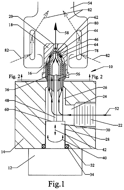
Modulating gas burner valve
A variable-orifice valve that feeds gas directly into a burner to hold a steady cooking temperature.
US 9,829,216 B2 · Title as filed: Solar collector comprising an opaque cover · Inventors: Prutsman; Jeffrey D. et al.
Sheet 1 of 9 from the published document. All sheets in the USPTO PDF
A solar heat collector whose dark opaque cover absorbs sunlight and passes the heat across a sealed air gap to a fluid-filled absorber.
A solar collector has an opaque cover heated by solar energy. Heat flows from the opaque cover by conduction, convection, and infrared emittance across a gap within an at least substantially airtight enclosure to an absorber containing a working fluid. The exterior surface of the opaque cover has high solar energy absorptance and the interior surface has high infrared emittance. The exterior surface preferably has low infrared emittance. In one embodiment, fully wetted surface geometry permits direct and reflected infrared absorption by the absorber. The opaque cover eliminates the weight, cost and other shortcomings of glass. A hollow continuous side wall with rounded corners provides an embodiment that is robust yet economical, that is easy to manufacture and seal, that permits a reduced thickness of the opaque cover and mitigates the destructive potential of severe winds, and that can withstand the compressive forces experienced by an evacuated solar collector.
The first 1 of 9 drawing sheets from the published document, cropped to the drawing. Every sheet is in the USPTO PDF.
Independent claims and the claims that build on them, read from each claim's text.
What the patent claimed, word for word. All of it is now free to use.
Not Applicable THE NAMES OF THE PARTIES TO A JOINT RESEARCH AGREEMENT
Not Applicable REFERENCE TO A SEQUENCE LISTING, A TABLE, OR A COMPUTER PROGRAM, LISTING COMPACT DISC APPENDIX
Not Applicable BACKGROUND OF THE INVENTION
Field of the Invention
The present invention relates to solar collectors, and more particularly to solar thermal collectors designed to heat a working fluid to temperatures within a range of 25° C. to 180° C.
Description of Related Art
The flat plate solar collector has not fundamentally changed since the 1970s. U.S. Pat. No. 4,011,856 to Gallagher
teaches an exemplary design that fairly represents the vast majority of glazed flat plate solar collectors in use today. Such solar collectors typically employ tempered glass with reduced iron oxide content as the cover plate material. The glass must be thick enough to prevent sagging of unsupported spans. The glass must also have impact resistance and, in high wind zones, must be attached to the solar collector assembly with a frame and fasteners capable of withstanding the dynamic air pressures generated by severe windstorms. Consequently, the glass cover plate is typically either 3.2 or 4 millimeters thick, with corresponding weights of about 8 and 10 kg/m.sup.2. The use of glass makes flat plate solar collectors difficult to handle and expensive to ship. Also, tempered glass is not impervious to breakage. While tempering produces excellent flat surface impact resistance, the edge strength is poor. A sheet of tempered glass can shatter when lateral compressive force (for example, the force from a solar collector being dropped on its side during handling) drives the head or length of an adjacent glazing frame screw into the edge of the glass.
Translucent plastics, including acrylics and polycarbonates, have been used as solar collector glazing in an attempt to reduce weight and cost. Unfortunately, these materials suffer significant reductions in transmittance over time due to discoloration and structural degradation, caused by accumulated exposure to ultraviolet radiation and stagnation temperatures. Plastic glazing materials also tend to experience unacceptable levels of outward bowing when exposed to the dynamic pressures associated with severe windstorms.
An additional problem for both transparent and translucent cover plate materials is that airborne dust and grime can accumulate on the glazing surface, which reduces solar energy transmittance. In many climates, the frequency and intensity of rainfall are not sufficient to remove accumulated dust and grime. Further, it is a practical reality that periodic manual glass cleaning is problematic for solar collectors on residential rooftops and in large commercial arrays.
The side walls of a typical glazed flat plate solar collector are formed of four elongated, straight aluminum extrusions, with 45-degree beveled ends and various extruded appendages extending outward from the vertical wall portions. The four side walls are joined at 90-degree angle corners, often reinforced with L-shaped brackets on the interior side of each corner. Screws, bolts, or rivets tighten the side walls to the L-shaped reinforcing brackets. These sharp angle corner joints have two shortcomings. First, the solar collector side walls expand and contract with daily temperature variations. Over time, repeated expansion and contraction can lead to small gaps at the corner joints. This problem may be exacerbated by a difference in the upper horizontal side wall and the lower horizontal side wall temperatures, leading to small but meaningful differences in the longitudinal expansion and contraction of the upper and lower horizontal side walls. With even the smallest corner gaps, moisture and particulate laden air infiltration into the solar collector interior will inevitably occur, urged by pressure differences between the air inside the solar collector and ambient air. Moisture and particulate intrusion eventually end up as a grimy film on the underside of the glazing, reducing solar energy transmittance. The corner joints discussed are seldom, if ever, sealed with an elastomeric material that might help prevent moisture intrusion over time. The lack of effective corner sealing is due in part to the practical difficulty of sealing the abrupt, planar and pointed surface intersections at the top and bottom of each corner joint. While the corner joints could be welded, this strategy imposes unacceptable labor costs and is incompatible with the most common frame material and finish, which comprises an anodized finish of an aluminum frame.
During severe windstorms, square corners on a solar collector increase dynamic pressure on the cover plate. Comparative tests of roof gravel scouring showed that aerodynamic corners can double the damage threshold wind speed compared to conventional square corners. Pressure measurements showed up to 75% reduction in uplift pressures in a roof corner test for an aerodynamic corner, when compared with a square corner. See Lin, et al., “Aerodynamic Devices for Mitigation of Wind Damage Risk,” 4th International Conference on Advances in Wind and Structures. AWAS 08. Jeju, Korea, May 29-31, 2008.
A problem closely related to the wind uplift pressure issue discussed above is that any structure comprising a blunt windward edge with square corners promotes formation and shedding of vortex currents along the edges disposed downwind from such corners. See Okamoto, S. and Uemura, N. “Effect of rounding side-corners on aerodynamic forces and turbulent wake of a cube placed on a ground plane,” Experiments in Fluids, 11, 58-64. Springer-Verlag. 1991.) If the frequency of the vortex shedding happens to match the resonance frequency of the structure, the structure will begin to resonate and the structure's movement can become self-sustaining Vortex shedding on a solar collector perimeter during a severe windstorm can literally shake roof shingles loose and start progressive undermining of the entire roof structure, leading to eventual catastrophic loss. Roof deck failure is the leading cause of catastrophic residential building damage during severe windstorms. Once a building loses one or more pieces of roof deck, damage increases exponentially as vast amounts of wind-driven water enter the structure. Insurance claim data show that damage escalates quickly once a roof deck starts to fail. Even if the walls remain intact and the roof trusses do not fail, loss of the roof deck typically results in losses greater than 50% of building insured value. See Applied Research Associates, Inc. “Development of Loss Relativities for Wind Resistive Features of Residential Structures,” Florida Department of Community Affairs (DCA Contract 02-RC-11-14-00-22-003), Version 2.2, Mar. 28, 2002.
The evacuated tube solar collector is an alternative to the glazed flat plate solar collector. U.S. Pat. No. 4,067,315 to Fehlner and Ortabasi
teaches an exemplary evacuated tube solar collector. The evacuated tubes of such solar collectors typically comprise 1.6 millimeter thickness borosilicate glass cylinders. While such glass cylinders do have a degree of impact resistance, breakage can nevertheless occur as a result of impacts by hail, wind-driven storm debris, errant golf balls and baseballs, and dropped tools. Breakage can also occur during shipping and handling.
Snow accumulation is also a problem for evacuated tube collectors. The vacuum that eliminates convective heat losses from inside the glass tube to ambient air also allows snow to accumulate on the glass tubes. The glass cover plate of a flat plate solar collector is warmed during sunny conditions by continual heat transfer from the hotter air on the underside of the glass to the cooler ambient air. However, the glass of an evacuated tube solar collector is only warmed by the small percentage of incident solar energy absorbed by the glass, and this heat is quickly lost to the cold ambient air that accompanies a snowfall. Thus, absent manual snow removal, evacuated tube solar collectors are rendered useless for some period of time after a snowfall.
Evacuated flat plate solar collectors have been proposed. U.S. Pat. No. 4,332,241 to Dalstein, et al. (1982), U.S. Pat. No. 7,810,491 to Benvenuti
and U.S. Pat. No. 8,161,965 to Palmieri
are exemplary designs. The Benvenuti '491 patent provides an excellent discussion of both tube and flat plate evacuated solar collectors. The Dalstein '241 patent teaches a complex double-walled frame, including an inner frame wall comprising four pieces of square tubing welded at 45-degree beveled sharp corners. The Dalstein '241, Benvenuti '491 and Palmieri '965 patents all teach various approaches to soldering or fusing metal to glass. These complex and relatively expensive processes are conceived to address the dissimilar materials and dissimilar rates of expansion and contraction of the glass cover plate and the metal frame walls. However, the Dalstein '241, Benvenuti '491 and Palmieri '965 patents do not solve the problems associated with flat plate solar collector glazing or sharp side wall corners, or the problem of snow accumulation on the outer glass surface of an evacuated solar collector.
The unglazed solar collector is another alternative to the glazed flat plate solar collector. Unglazed plastic solar collectors, with carbon black added to the plastic resin to enhance solar energy absorptance and combat the effects of prolonged exposure to ultraviolet radiation, are widely used for swimming pool heating. U.S. Pat. No. 3,934,323 to Ford, et. al.
and U.S. Pat. No. 4,060,070 to Harter
teach examples of unglazed plastic solar collectors. While swimming pool heating requires temperatures between 25° C. and 32° C., unglazed plastic solar collectors have been employed for potable water heating, which requires temperatures between about 45° C. and 60° C.
Unglazed solar collectors are capable of delivering 60° C. water when the flow rate of the working fluid is reduced. Unfortunately, though, unglazed solar collectors suffer much greater convective heat losses than glazed flat plate solar collectors when the ambient air temperature falls below the solar collector fluid inlet temperature. Wind compounds the problem. Poor cold weather performance is acceptable for solar swimming pool heating because the goal in most climates is only to extend the swimming season by a few extra months. Other water heating applications require hot water on a year-round basis.
The present invention is directed to a solar collector comprising an opaque cover. Solar energy is absorbed by the opaque cover and converted to heat, which is transferred from the opaque cover by conduction, convection, and infrared emittance across a gap within an at least substantially airtight enclosure to an absorber containing a working fluid. The exterior surface of the opaque cover has high solar energy absorptance and the interior surface has high infrared emittance. The exterior surface preferably also has low infrared emittance. The composition, structure and thermal mass of the opaque cover and the composition, structure and thermal mass of the absorber are selected to promote an operating relationship whereby the interior surface of the opaque cover is hotter than the absorber surface.
One embodiment is directed to a solar collector comprising a continuous side wall having a hollow cross-section and rounded corners. The continuous side wall is economical to fabricate yet unusually strong compared to current art solar collector frame walls. The rounded corners of the continuous side wall reduce windload stresses during hurricane-force winds, which permits a reduced thickness of the opaque cover and can reduce potential catastrophic roof damage. The form and inherent strength of the continuous side wall also allow alternatives for reducing convective heat loss to the ambient air. In a most economical embodiment of a continuous side wall, convective heat loss is reduced by the dead air space in the hollow portion of the continuous side wall. In a second alternative embodiment, convective heat loss can be further reduced by injecting mass insulation, such as, for example, polyurethane foam, into the hollow portion of the continuous side wall. In a third alternative embodiment, the inherent strength of the continuous side wall and, in particular, the inherent strength of the rounded corners combine with the simplicity and ease of airtight sealing a solar collector of the present invention to permit evacuation of the solar collector interior. Evacuating the solar collector interior virtually eliminates convective heat losses.
In higher performance embodiments, the opaque cover preferably has a selective coating on the exterior surface with high solar energy absorptance and low infrared emissivity, and preferably has a coating on the interior surface with high infrared emissivity. The absorber preferably has a selective coating with high infrared absorptance.
While not wishing to be bound to a single theory as to the optimal structure for promoting heat transfer from the opaque cover to the absorber, one preferred embodiment is directed to a solar collector that achieves a greater absorber wetted surface exposed to infrared energy transfer by providing a spaced apart relationship above, below and between the fluid passageway tubes of the absorber, thereby providing for infrared energy transfer not only directly from the opaque cover to the absorber but also indirectly from a highly reflective surface below the absorber to the underside surfaces of the absorber.
FIG. 1 illustrates an exterior perspective view of a prototype solar collector comprising one exemplary embodiment, installed on a roof.
FIG. 2 illustrates a cross-sectional view of one basic embodiment of an opaque cover, a housing, and an absorber. The absorber configuration depicted is not critical to the invention.
FIGS. 3A, 3B, 3C, 3D and 3E illustrate cross-sectional views of several exemplary embodiments of an opaque cover of the present invention.
FIG. 4 and FIG. 5 illustrate cross-sectional views showing three exemplary fluid passageway tubes of one preferred embodiment comprising an absorber having fluid passageway tubes in a spaced apart relationship.
FIG. 6 illustrates a bird's-eye view of an embodiment directed to a continuous side wall, with the opaque cover removed to reveal the continuous side wall and a plurality of transverse frames. The specific configuration of the generic absorber structure depicted is not critical to the invention.
FIGS. 7A, 7B and 7C illustrate cross-sectional views of various embodiments comprising a continuous side wall and transverse frames. The generic absorber depicted is not critical to the invention and is shown only to illustrate a spaced apart relationship between the absorber and the opaque cover, between the absorber and the continuous side wall, and between the absorber and the back plate.
FIG. 8 illustrates a perspective view of one preferred embodiment with the opaque cover and back plate removed to reveal the continuous side wall having rounded corners, the transverse frames, and an absorber having substantially parallel fluid passageway tubes in a spaced apart relationship.
FIG. 9 illustrates a bird's-eye view of an exemplary embodiment directed to an evacuated solar collector comprising a plurality of heat pipes connected to an internal heat exchange manifold.
Turning now to FIG. 1 , the present invention is directed to a solar collector comprising an opaque cover 10 disposed to receive incident solar energy and coupled to an upper portion of a housing 12 . A cross-sectional view of one embodiment, taken at section line 2 - 2 of FIG. 1 , is illustrated in FIG. 2 . The opaque cover 10 preferably comprises a planar structure but can also be dome-shaped, corrugated, or any other shape suitable for receiving incident solar energy and providing for structural integrity under anticipated loads. The housing 12 may be of any shape and construction suitable to isolate an absorber 26 from ambient air, provided that coupling of the opaque cover 10 to an upper portion of the housing 12 defines an at least substantially airtight enclosure 14 . The absorber 26 is disposed within the enclosure 14 in an opposing spaced apart relationship with the opaque cover 10 .
The present invention is directed to a solar collector that operates by a fundamentally different principle than glazed flat plate solar collectors of the current art. Instead of transmitting incident solar energy through a transparent or translucent glazing material, the opaque cover 10 absorbs solar energy at its exterior surface 22 , the absorbed radiant energy heats the opaque cover 10 , then, in addition to any heat transfer from the opaque cover 10 to the absorber 26 via conduction or convection, infrared energy is emitted from the interior surface 24 to the absorber 26 . The exterior surface 22 has solar energy absorptance greater than 0.80 and the interior surface 24 has infrared emittance greater than 0.80. For improved thermal performance, the exterior surface 22 preferably has infrared emittance of less than 0.30.
In a single-glazed, flat plate solar collector circulating a working fluid at temperatures of 40-60° C., the glass cover plate temperature is about 50-70% of the absorber mean surface temperature. In stark contrast to a glazed flat plate solar collector, the interior surface 24 of the opaque cover 10 is hotter than the absorber 26 during normal operation, which facilitates net radiant energy transfer from the opaque cover 10 to the absorber 26 . Without being bound to any particular theory, it is believed that the temperature of the interior surface 24 of the opaque cover 10 should preferably be as hot as possible during normal operation because infrared emittance increases to the fourth power of the temperature of an emitting surface. The temperature of the interior surface 24 can be maximized by material selection and thickness directed to high thermal conductivity and low thermal mass such as, for example, an interior surface 24 comprising a 0.813 millimeter thickness aluminum sheet.
The opaque cover 10 can employ a variety of strategies to meet a range of performance goals and cost considerations. FIG. 3A illustrates a basic embodiment of the opaque cover 10 comprising a central region 20 , the exterior surface 22 , and the interior surface 24 as a homogeneous structure and composition. One exemplary homogeneous opaque cover 10 , directed to low cost, comprises a molded polymer structure incorporating carbon black in the resin. Such a composition has high absorptance at the exterior surface 22 and high emissivity at the interior surface 24 . While emissivity of the exterior surface 22 in this example is undesirably high, the reduction in performance can be acceptable for an embodiment of the present invention directed primarily to a very low cost solar collector.
FIG. 3B illustrates an embodiment of the opaque cover 10 wherein each of the exterior surface 22 and the interior surface 24 comprises a selective coating. The term “selective coating” as used herein refers to paints, plating, resins, sheets, laminates, films, vacuum deposited metals, and other coatings that increase or reduce the radiant energy absorptance of a surface, increase or reduce the radiant energy reflectance of a surface, increase or reduce the radiant energy emittance of a surface, deliver a preferred range of absorptance and emittance, or deliver a preferred range of the ratio of absorptance to emittance. Exemplary selective coatings include oxides of titanium nitride or other metals, anodized aluminum, black chromium electroplated over a nickel substrate, ceramic matrices, quartz-encapsulated bi-metallic alloys, layered compositions of silicone polymers and metal oxides, black lacquer, urethane paints, silicone paints, compositions of polypropylene polymers and carbon black, compositions of butyl or EPDM rubber incorporating carbon black, and individual sheets or multilayer stacks of polymer films such as, for example, stacks of transparent cross-stretched birefringent sheets.
In embodiments comprising selective coatings, the exterior surface 22 is preferably selective for enhanced absorption of incident solar energy and reduced emittance of infrared energy, and the interior surface 24 preferably has high infrared emittance. A variety of commercial selective coatings are available that offer solar energy absorptivity ranging from 0.90 to 0.96, with simultaneous infrared emissivity ranging from 0.05 to 0.30. The selection of selective coatings can be based upon cost and thermal performance targets. In an exemplary low cost embodiment, a selective coating for the exterior surface 22 might have absorptivity of 0.87 and emissivity of 0.90; while an exemplary high thermal performance embodiment might have absorptivity of 0.95 and emissivity of less than 0.30.
The central region 20 of the opaque cover 10 can be solid such as, for example, a sheet of aluminum, molded polymer, fiberglass, or carbon fiber or, alternatively, comprise a complex structure such as, for example, a honeycomb sandwich structure having honeycomb core walls disposed in a perpendicular sandwiched relationship between each of the exterior surface 22 and the interior surface 24 . In such a honeycomb sandwich structure, each of the exterior surface 22 and the interior surface 24 comprise facing sheets such as, for example, aluminum sheets having selective coatings applied on the sides distal to the honeycomb core walls. The honeycomb sandwich structure combines high compressive strength and weight savings. Further, the honeycomb sandwich structure reduces convective heat loss by providing air spaces within the honeycombs that dampen convection because of very low volume. While a honeycomb sandwich structure reduces convective heat loss, energy transfer via direct infrared energy emittance from the exterior surface 22 to the interior surface 24 across the air spaces in the honeycombs is enhanced by conduction via thermal bridging through the honeycomb core walls, which are in direct contact with each of the exterior surface 22 and the interior surface 24 . Alternatively, the air spaces in the honeycomb structure may be filled with material having thermal conductivity less than 2 W/m ° C. at 25° C. or greater than 15 W/m-° C. at 25° C.
The exterior surface 22 of the opaque cover 10 is directly exposed to the ambient air. Atmospheric moisture generally and acidic rain in particular can attack some selective coatings by wet corrosion. If the exterior surface 22 comprises a selective coating susceptible to wet corrosion, it is advantageous to apply a transparent protective coating 32 over the selective coating as illustrated in FIG. 3C . The transparent protective coating 32 can be a simple transparent “hardcoat” layer or a multilayer polymer stack film that further comprises adhesive or polymer layers spectrally selective to reflect ultraviolet wavelengths. It is well known in the art of polymer films for sun control that adhesives having additives to selectively absorb ultraviolet radiation, or film sheets that selectively reflect ultraviolet radiation, can be placed in a layer proximal to a surface receiving incident solar energy to enhance longevity of both the stack and structures and surfaces for which sun control is sought.
As disclosed above, the interior surface 24 of the opaque cover 10 preferably has high emittance of infrared energy. Since the interior surface 24 is preferably hotter than the absorber 26 during normal operation, absorptance by the interior surface 24 of infrared energy reradiated from the absorber 26 is not believed to be a significant concern. Many coatings, such as, for example, black paints (including compositions comprising silicones and urethanes), and paint, plastic, acrylic, and rubber compositions incorporating carbon black combine economy, durability, and high emissivity. See Clatterbuck, Caroll H. and Scialdone, John J. “NASA Technical Memorandum 100768: An Evaluation of Two Flat-Black Silicone Paints for Space Application,” National Aeronautics and Space Administration, Goddard Space Flight Center, Greenbelt, Md., December 1990, for an overview of high emissivity paints. Any film applied to the interior surface 24 will have enhanced longevity due to the absence of exposure to ultraviolet radiation.
FIG. 3D illustrates another alternative embodiment of the present invention comprising a transparent layer 34 applied to the interior surface 24 of the opaque cover 10 . The transparent layer 34 has selective reflectivity in the infrared wavelengths. An exemplary transparent layer 34 comprises a cross-stretched stack of birefringent polymer film sheets. It should be noted that such cross-stretched stacks are available in assembled form such as, for example, multilayer optical films manufactured by 3M.
As disclosed above, the temperature of the interior surface 24 is preferably as hot as possible during normal operation. In stark contrast, the temperature of the exterior surface 22 is preferably as cool as possible to reduce both infrared energy emittance to the sky and convective heat loss to the ambient air. Such an ideal differential relationship is difficult to achieve in practice. However, FIG. 3E illustrates yet another alternative embodiment of the present invention comprising a laminated structure of the opaque cover 10 that minimizes convective heat loss from the exterior surface 22 while simultaneously maximizing the temperature and consequent infrared energy emittance of the interior surface 24 by employing different materials for an exterior layer 36 and an interior layer 38 of the central region 20 . For example, and in addition to selective coatings and protective or reflective coatings comprising the exterior surface 22 and the interior surface 24 , the exterior layer 36 comprises an insulating layer with low thermal conductivity and the interior layer 38 comprises a layer with high thermal conductivity. The insulating aspect of the exterior layer 36 can be further enhanced by high thermal mass. The high thermal conductivity aspect of the interior layer 38 can be further enhanced by low thermal mass. Without being bound to any particular theory, it is believed that the insulating exterior layer 36 of the exemplary laminated structure, while reducing convective heat loss, only minimally impacts conductive heat transfer of absorbed solar energy to the interior surface 24 because the insulating aspect of the exterior layer 36 increases not only resistance to convective heat loss at the exterior surface 22 but also the thermal capacitance of the opaque cover 10 .
The alternative embodiments of the opaque cover 10 disclosed above are intended to be merely illustrative examples and not exhaustive. Within the scope of the present invention, many more materials, alternative combinations of the various aspects, and modifications in addition to those described above are possible without departing from the inventive concepts disclosed.
The absorber 26 is disposed within the enclosure 14 in an opposing spaced apart relationship with the opaque cover 10 . At least inlet and outlet conduits 28 , shown in FIG. 6 , are provided to supply and extract, respectively, the working fluid to and from the solar collector. The specific design, flow configuration, and construction aspects of the absorber 26 and conduits 28 are not critical. The present invention can be used with any absorber design, including absorbers comprising, for example, integral storage, fin structures, opposing and generally planar sheets joined to define a vessel, serpentine (serial) or harp (parallel) interconnected tubes, heat pipes, and air ducts, so long as the interior surface 24 of the opaque cover 10 is hotter than the surface of the absorber 26 during normal operation. In one alternative embodiment comprising integral storage for the working fluid, the integral storage capacity of the absorber 26 is preferably between 20 and 100 liters per square meter of planar surface area of the opaque cover 10 .
The preferred differential temperature relationship of the interior surface 24 and the absorber 26 can be enhanced by increasing the ratio of wetted surface area of the absorber 26 to the total planar surface area of the opaque cover 10 exposed to incident infrared energy. A higher wetted surface area of the absorber 26 allows the working fluid to more completely cool the absorber 26 as heat is extracted therefrom and transferred into the working fluid. The absorber 26 may also be alternatively or further cooled by selection of an absorber 26 material with lower thermal conductivity, especially in combination with a fully wetted surface of the absorber 26 because thermal conductivity is not critical to radiant energy transfer.
FIG. 4 illustrates one preferred embodiment wherein the absorber 26 comprises fluid passageway tubes 40 without fins, in a spaced apart relationship with a highly reflective surface 42 disposed beneath the tubes. Infrared energy first emitted 44 from the interior surface 24 of the opaque cover 10 that passes between the tubes 40 of the absorber 26 can be reflected 46 back to the undersides of such tubes 40 . The highly reflective surface 42 may be a sheet of unpolished or polished aluminum, an aluminum foil, a reflective paint composition, or a polymer or metalized polymer film spectrally reflective for infrared wavelengths.
Infrared energy emitted from a planar surface is diffuse. Accordingly, the spaced apart relationship of the tubes 40 and reflective surface 42 exposes the full 360-degree circumference of each tubes 40 to infrared energy first emitted 46 by the interior surface 24 of the opaque cover 10 . Further, as illustrated in FIG. 5 , when the average centerline spacing 50 of parallel aligned tubes 40 is between 0.75 and 1.00 times the average circumference of a tube 40 , total circumferential outer surface area of the tubes can approximate 100% of the planar surface area of the opaque cover 10 . In another aspect, the full 360-degree circumference of each fluid passageway tube 40 and the full 360-degree circumference of any connecting U-bends, or manifold structures in a parallel flow configuration, preferably have a coating 48 with high absorptance. Alternatively, high absorptance may be incorporated into a polymer absorber 26 such as, for example, by incorporating carbon black in the polymer resin. The selective coating 48 preferably has infrared absorptance greater than 0.90.
The spaced apart relationship of the absorber 26 and the opaque cover 10 preferably defines a gap 52 of at least 3 millimeters, and the spaced apart relationship of the absorber 26 and the highly reflective surface 42 preferably defines a gap 54 of at least 3 millimeters. In one preferred alternative embodiment of the present invention, the spaced apart relationships between the absorber 26 and the opaque cover 10 and between the absorber 26 and the highly reflective surface 42 are enabled by a plurality of transverse frames 70 , which are illustrated in FIG. 6 and more fully described below.
The disclosed fully wetted surface geometry is less expensive and involves less material than a nominally fully wetted surface absorber comprising the same material, tube diameter and wall thickness, either without spacing between fluid passageway tubes or with substantially less spacing between fluid passageway tubes.
A wide variety of absorber structures and materials can be employed. The fluid passageway tubes 40 can be copper, bent or brazed to U-shaped copper fittings to create a serpentine (serial) fluid flow pattern. Alternatively, substantially parallel aligned copper tubes 40 may be brazed to copper header manifold tubes, creating a parallel flow pattern. Tubes 40 can also be aluminum. Aluminum is less expensive than copper, even where a greater tube 40 wall thickness is required for a given fluid pressure, to compensate for the lower tensile strength of aluminum. Aluminum has excellent formability characteristics for bending and is lighter and less expensive than copper. Copper has higher thermal conductivity than aluminum but the difference is trivial in an absorber 26 comprising a 100% wetted surface, where radiant heat transfer is a significant component of total heat transfer.
The interconnected fluid passageway tubes 40 of the absorber 26 can also be a plastic tubing such as, for example, polypropylene or cross-linked, high density polyethylene (“PEX”) tubing, or a PEX-AL-PEX variant wherein the tube 40 walls comprise an aluminum layer sandwiched between PEX inner and outer layers. Any alternative tube 40 material selected should be capable of withstanding stagnation temperatures associated with the particular convective heat loss control strategy employed (e.g., dead air space, mass insulation, or evacuation). For example, PEX tubing would not be suitable in an embodiment directed to an evacuated solar collector, or in embodiments comprising mass insulation. The tubes 40 can also be a synthetic rubber such as, for example, ethylene propylene diene monomer (“EPDM”) rubber, which has a higher operating temperature range than PEX tubing provided; however, that EPDM rubber may not be suitable where potable water containing chlorine will circulate through the absorber 26 . It should be noted that the present invention is directed to a solar collector wherein all materials and surface coatings of the absorber 26 are protected from exposure to ultraviolet radiation by the opaque cover 10 , which is not the case in glazed flat plate and evacuated tube solar collectors.
FIG. 6 illustrates a birds-eye view of one embodiment of the present invention directed to a solar collector comprising a continuous side wall 60 having a hollow cross section 62 and rounded corners 64 . Transverse frames 70 support the absorber 26 and create the spaced apart relationship between the absorber 26 and the opaque cover 10 (not shown), between the absorber 26 and the continuous side wall 60 , and between the absorber 26 and a back plate 66 (not shown). The generic absorber 26 structure illustrated in FIG. 6 is not critical to the invention. The outside surface radius of each rounded corner 64 , which outside surface is exposed to ambient air, is preferably at least 8 centimeters.
A cross-sectional view taken at section line 7 - 7 of FIG. 6 is illustrated in FIG. 7A . The opaque cover 10 is coupled to an upper portion of the continuous side wall 60 and a back plate 66 is coupled to a lower portion of the continuous side wall 60 . The continuous side wall 60 , the opaque cover 10 , and the back plate 66 define an enclosure 14 . The method of coupling, which may comprise fasteners, adhesives, brackets or parts that snap together by the temporary deformation of one or more mating surfaces, is not critical to the invention. However, it is preferable to provide a coupling method whereby the opaque cover 10 can be removed and replaced, for inspection and servicing of the absorber 26 , without causing permanent damage or deformation. It is also preferable that the method of coupling promote preservation of the at least substantially airtight character of the enclosure 14 over the anticipated service life of the solar collector. A gasket material 68 may be interposed at the contact perimeter between the continuous side wall 60 and the opaque cover 10 , and at the contact perimeter between the continuous side wall 60 and the back plate 66 , to provide a seal that serves to reduce the intrusion of moisture, dirt, and particulates into the enclosure 14 . The contact perimeter gasket material 68 is illustrated in FIGS. 7B and 7C . The contact perimeter gasket material 68 may be eliminated in alternative embodiments directed to low manufacturing cost.
Alternative embodiments of the continuous side wall 60 can be formed of extruded plastic, shaped composites, or other suitable materials. In one preferred embodiment, a single piece of hollow aluminum square tube is bent within a rotary compression bending machine to form rounded corners 64 of a generally rectangular continuous side wall 60 . For example, a 6 meter×25 millimeter square piece of 1.575 millimeter gauge thickness 6063-T52 aluminum square tube can be bent to form a continuous side wall 60 measuring approximately 0.61 meters×2.44 meters with about 8 centimeter radius rounded corners, the radius being measured at the outside exterior surface of the aluminum square tube. Exemplary rotary compression bending machines are manufactured by Pedrick Tool and Machine Company of Cinnaminson, N.J. The two ends of the square tube are welded and smoothed at a single point along a remaining straight section of the square tube, to form the continuous side wall 60 without corner joints.
Holes can be drilled through the continuous side wall 60 to accommodate fluid inlet and outlet passageways, for fitting ancillary devices or mounting hardware, and for injecting foam insulation into the hollow cross-section 62 . It is also noteworthy that some holes, such as, for example, holes for mounting hardware or for injecting foam insulation, may only penetrate the exterior portion of the continuous side wall 60 , advantageously limiting the number of penetrations through the interior portion of the continuous side wall 60 for the purposes of convective heat loss reduction an, in an evacuated solar collector embodiment, vacuum preservation. Steps unrelated to the bending operation such as, for example, drilling holes in the continuous side wall 60 , can be performed prior to the bending operation. This advantageously allows such unrelated tasks to be performed on straight stock of different lengths at the same work station. Thus, a space-efficient work station arrangement can be employed for processing straight stock for solar collectors of varying sizes. It is not necessary to have a different workstation for the non-bending operations associated with fabricating each different size of the continuous side wall 60 .
The structure and composition of the opaque cover 10 are determined in part by the anticipated dynamic air pressures to which the solar collector may be subjected. In this regard, the rounded corners 64 reduce dynamic air pressure on the opaque cover 10 during high winds. Consequently, the opaque cover 10 can have less mass than might otherwise be required under a given windload requirement. In addition to material cost savings, an opaque cover 10 with reduced mass will generally attain higher temperatures when exposed to incident solar energy, which is desirable for increasing infrared heat transfer to the absorber 26 .
The description continues in the full USPTO document.
Fees are due 3.5, 7.5 and 11.5 years after grant. This patent expired on November 28, 2025, so the fee marked "not paid" was the one that went unpaid.
SOLAR COLLECTOR COMPRISING AN OPAQUE COVER
Filed Apr 2014 · published Oct 2014Solar collector comprising an opaque cover
Filed Apr 2014 · granted Nov 2017Earlier publications, parents and continuations. None of them can still be enforced, or this patent would not be listed.
Prior art cited by the examiner or applicant. Useful when you check your own idea for novelty.
Names, summaries, modern angles and build ratings are Patent Yard's editorial notes. Everything else on this page comes from the documents linked above.