 Lapsed, fee not paid4 drawings
Robotics & Automation · US 8,677,854 B2
Modular robot arm joints
An industrial robot arm built from modules, each with two members that rotate about an axis.
US 9,827,670 B1 · Title as filed: Coaxial finger face and base encoding · Assignee: X Development LLC · Inventors: Strauss; Marc
Sheet 1 of 7 from the published document. All sheets in the USPTO PDF
Encoders at each finger's face and base let a robot gripper feel how it is touching an object.
Disclosed herein are implementations that relate to determining tactile information using encoders coupled to one or more fingers of a robotic gripping device. The robotic gripping device may include a finger. The finger may include a deformable front face, a base link, a first encoder, and a second encoder. The first encoder may be coupled to the base link of the finger, and configured to detect a grip angle of the finger while the robotic gripping device is gripping an object. The second encoder may be coupled to the deformable front face of the given finger, proximate to the base link of the finger. Additionally, the second encoder may be configured to detect a bend angle of the deformable front face of the finger while the robotic gripping device is gripping the object.
As technology advances, various types of robotic devices are being created for performing a variety of functions that may assist users. Robotic devices may be used for applications involving material handling, transportation, welding, assembly, and dispensing, among others. Over time, the manner in which these robotic systems operate is becoming more intelligent, efficient, and intuitive. As robotic systems become increasingly prevalent in numerous aspects of modern life, it is desirable for robotic systems to be efficient. Therefore, a demand for efficient robotic systems has helped open up a field of innovation in actuators, movement, sensing techniques, as well as component design and assembly. Robotic devices, such as robotic legs and arms, may include various components or attachments that are designed to interact with the environment. Such components may include robotic feet and ha
The first 3 of 7 drawing sheets from the published document, cropped to the drawing. Every sheet is in the USPTO PDF.
Independent claims and the claims that build on them, read from each claim's text.
What the patent claimed, word for word. All of it is now free to use.
As technology advances, various types of robotic devices are being created for performing a variety of functions that may assist users. Robotic devices may be used for applications involving material handling, transportation, welding, assembly, and dispensing, among others. Over time, the manner in which these robotic systems operate is becoming more intelligent, efficient, and intuitive. As robotic systems become increasingly prevalent in numerous aspects of modern life, it is desirable for robotic systems to be efficient. Therefore, a demand for efficient robotic systems has helped open up a field of innovation in actuators, movement, sensing techniques, as well as component design and assembly.
Robotic devices, such as robotic legs and arms, may include various components or attachments that are designed to interact with the environment. Such components may include robotic feet and hands, which may include additional components that can be used to support, stabilize, grip, and otherwise allow a robotic device to effectively carry out one or more actions.
In particular, robotic arms may include one or more “end effectors” that interact with the environment. For example, end effectors may be impactive (such as a claw), ingressive (such as a pin or needle), astrictive (such as a vacuum or suction element) or contigutive (requiring contact for adhesion, such as glue).
A robotic gripping device is disclosed that includes a finger. The finger may include a deformable front face, a base link, a first encoder, and a second encoder. The first encoder may be coupled to the base link of the finger, and configured to detect a grip angle of the finger while the robotic gripping device is gripping an object. The second encoder may be coupled to the deformable front face of the given finger, proximate to the base link of the finger. Additionally, the second encoder may be configured to detect a bend angle of the deformable front face of the finger while the robotic gripping device is gripping the object.
In another example, a robot is described. The robot may include a finger. The finger may include a deformable front face, a base link, a first encoder, and a second encoder. The first encoder may be coupled to the base link of the finger, and configured to detect a grip angle of the finger while the robotic gripping device is gripping an object. The second encoder may be coupled to the deformable front face of the given finger, proximate to the base link of the finger. Additionally, the second encoder may be configured to detect a bend angle of the deformable front face of the finger while the robotic gripping device is gripping the object. The robot may also include a control system configured to (i) receive sensor data indicative of the grip angle of the finger from the first encoder of the finger, and (ii) receive sensor data indicative of the bend angle of the deformable front face of the finger from the second encoder of the finger.
In yet another example, a method is described. The method involves gripping, by a finger of a robotic gripping device, an object. The method also involves detecting, by a first encoder coupled to a base link of the finger, a grip angle of the finger while the robotic gripping device is gripping the object. The method further involves detecting, by a second encoder coupled to a front face of the finger and proximate to the base link of the finger, a bend angle of the deformable front face of the given finger while the robotic gripping device is gripping the object.
In yet a further example, the robotic gripping device may include means for gripping an object with a finger. The finger may include a deformable front face, a base link, a first encoder, and a second encoder. The first encoder may be coupled to the base link of the finger, and the second encoder may be coupled to the deformable front face of the given finger, proximate to the base link of the finger. The robotic gripping device may also include a means for detecting a grip angle and bend angle of an object while the robotic gripping device is gripping the object. The first encoder may be configured to detect a grip angle of the finger while the robotic gripping device is gripping an object. Additionally, the second encoder may be configured to detect a bend angle of the deformable front face of the finger while the robotic gripping device is gripping the object.
The foregoing summary is illustrative only and is not intended to be in any way limiting. In addition to the illustrative aspects, embodiments, and features described above, further aspects, embodiments, and features will become apparent by reference to the figures and the following detailed description and the accompanying drawings.
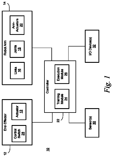
FIG. 1 illustrates a configuration of a robotic system, according to an example implementation.
FIG. 2 illustrates an example robotic arm, according to an example implementation.
FIG. 3 illustrates the example robotic arm of FIG. 2 having a robotic gripping device, according to an example implementation.
FIG. 4 illustrates an example robotic gripping device, according to an example implementation.
FIGS. 5A, 5B, and 5C illustrate an example finger of a robotic gripping device, according to an example implementation
FIG. 6A illustrates an example robotic gripping device in an open position, according to an example implementation.
FIG. 6B illustrates an example robotic gripping device grasping an object by the fingertips of the robotic gripping device, according to an example implementation.
FIG. 6C illustrates an example robotic gripping device grasping an object near the base of the fingers of the robotic gripping device, according to an example implementation.
FIG. 6D illustrates an example robotic gripping device grasping an object near the middle portion of the fingers of the robotic gripping device, according to an example implementation.
FIG. 7 is a flow chart, according to an example implementation.
The following detailed description describes various features and functions of the disclosed devices, systems, and methods with reference to the accompanying figures. The illustrative device, system, and method embodiments described herein are not meant to be limiting. It should be understood that the words “exemplary,” “example,” and “illustrative,” are used herein to mean “serving as an example, instance, or illustration.” Any implementation, embodiment, or feature described herein as “exemplary,” “example,” or “illustrative,” is not necessarily to be construed as preferred or advantageous over other implementations, embodiments, or features. Further, the implementations and embodiments described herein are not meant to be limiting. It will be readily understood that certain aspects of the disclosed devices, systems, and methods can be arranged and combined in a wide variety of different configurations, all of which are contemplated herein. Additionally, the following detailed description describes various features and functions of the disclosure with reference to the accompanying Figures. In the Figures, similar symbols typically identify similar components, unless context dictates otherwise. I.
Robotic arms may include many different types of end effectors. One often used type of end effector is a gripper or a robotic gripping device, which allows a robotic arm to grip or grasp an object. Many robotic gripping devices include one or more fingers that act to grasp an object in a pincer-like or pinching manner. In some cases, these robotic gripping devices may include underactuated fingers. Underactuated fingers include the benefit of less complexity and easier control because each phalanx of the finger is not independently actuated. Instead, the full finger is actuated together.
In some instances, however, it may be difficult to know the shape of an underactuated finger when an object is grasped because each phalanx is not independently actuated. It may also be difficult to know the size, position, or location of the object being grasped. In many applications, it may be beneficial to know the position, orientation, or shape of a finger. It may also be beneficial to know the size, position, location, or shape of the object being grasped, or the grip quality of a finger grasping the object. To accomplish this task, one technique may include attaching one or more sensors to the components of the robotic gripping device that can detect the position (e.g., angle) of a finger. However, using multiple sensors or particularized sensors for a specific purpose may require a complex control system and/or a complex arrangement of components. It may also limit mobility, increase the cost of manufacturing, or otherwise detract from the efficiency and usefulness of a robotic device.
Example embodiments described herein provide devices, systems, and/or methods without the use of overly complex sensors and control systems. Example embodiments of a robotic gripping device may include a finger with a first encoder and a second encoder to acquire an approximation of the shape of the finger while grasping an object, or determine the size, position, or location of the object being grasped. The finger may also include a deformable front face and a base link. A base link may be, for example, a joint or linkage adjacent to a bottom portion of the front face of a finger that couples the finger to an actuator of the robotic gripping device. The actuator may rotate the base link of the finger in order to move the finger towards or away from an object. The first encoder may be coupled to the base link of a finger, and the second encoder may be coupled to the deformable front face of the finger, proximate to the base link of the finger. Keeping the first encoder and second encoder proximate to the base link and/or proximate to each other may reduce cost and footprint of the robotic gripping device, while making it easier to enshroud each encoder. Additionally, keeping the first encoder and second encoder proximate to the base link (rather than an encoder or sensor on the finger) may allow the finger to remain without any active (e.g., powered) elements. A passive (e.g., non-powered) finger may be less expensive and easier to replace for maintenance. To further reduce the complexity of the robotic gripping device, the first encoder and second encoder may be aligned on the same rotational axis.
In some examples, the first encoder may be configured to detect a grip angle of a finger while the robotic gripping device is gripping an object. A grip angle may be the amount of rotation of a finger through its respective axis (e.g., half turn, quarter turn, twenty degree turn, etc.) from an open position (e.g., starting position of the robotic gripping device) to a position in which the finger is in contact with an object.
Further, the second encoder may be configured to detect a bend angle of the deformable front face of the finger while the robotic gripping device is gripping an object. A bend angle may be the amount of curvature, or bendedness of the deformable front face of the finger after the finger makes contact with an object. The front face may continue to deform, bend, curve, warp, stretch, or otherwise alter its shape (thereby increasing the bend angle) while more pressure is applied to an object. The bend angle may be measured from the bottom of the deformable front face near the base of the finger, and the overall bendedness or deformity of the front face may be determined based on this measurement.
The robotic gripping device may also include an actuator configured to move a finger towards or away from an object. The actuator may be coupled to the base link of the finger. In such arrangement, the actuator may be configured to move the finger by moving the base link of the finger.
Additionally, the robotic gripping device may include a control system that is configured to receive sensor data from the first encoder and the second encoder. For example, the control system may receive sensor data indicating the grip angle of the finger while the robotic gripping device is gripping an object. In a further example, the control system may receive sensor data indicating the bend angle of the finger while the robotic gripping device is gripping the object.
Based on the grip angle and the bend angle, the control system may determine a grip quality of the finger. In many applications of robotic gripping devices in which the robotic gripping device interacts with an environment, the grip quality of a finger gripping an object is of particular relevance. A grip quality may be, for example, a measure of what portion of the front face is in contact with the object being grasped. In other words, it may provide an approximation of the shape of the finger when an object is grasped. Additionally, grip quality may be a measure of how firmly an object is grasped by the robotic gripping device, or how much control the robotic gripping device has over an object that is grasped.
In some instances, however, the robotic gripping device may end up with an undesirable grip quality when grasping an object. For example, the object may inadvertently move while one or more fingers are moved towards the object to grasp the object. In another example, based on optical sensor data received, the control system may cause the robotic gripping device to place its fingers in a certain position before grasping an object. In this example, however, the optical sensor data associated with the object and/or environment surrounding the robotic gripping device may be inaccurate, thereby causing an undesirable grip quality when grasping the object.
To improve the grip quality of the finger, the control system may be configured to cause the finger to adjust its grip. For example, the robotic gripping device may grasp an object by the fingertips of the finger at a certain grip angle and bend angle. To improve the grip quality (e.g., to have better control over the object), it may be desirable to adjust the grip angle of the finger and/or bend angle of the front face of the finger. In some examples, it may be desirable to grasp the object at the middle portion of the finger instead of grasping the object by the fingertips. To adjust the grip, the control system may cause the actuator to move the finger away from the object that is being grasped by the fingertips, change the position of the robotic gripping device, and then cause the actuator to move the finger back towards the object to grasp the object at the middle portion of the finger.
Additionally, based on the grip angle and the bend angle, the control system may determine the shape and/or size of the object being grasped. Determining the shape and/or size of the object is of particular relevance as it provides additional tactile information in an environment in which the robotic gripping device interacts. For example, the control system of the robotic gripping device may distinguish a rectangular object from a cylindrical or spherical object. A cylindrical or spherical object may cause a greater bend angle as the front face of the finger will likely deform or bend into the curvature of such object as the finger makes contact with the object and further applies pressure to it.
In addition, based on the grip angle and the bend angle, the control system may determine additional tactile information, such as the location of the object being grasped. Determining the location of the grasped object within the robotic gripping device is of particular relevance as it provides the ability to deterministically bring the object into physical interaction with the environment. For example, if the object is a tool, knowing the location of the tool within the robotic gripping device is necessary to bring the tool into locationally accurate contact with the workpiece. In another example, knowing the location of the object within the robotic gripping device allows the robot to set the object down gently on a surface. II.
FIG. 1 illustrates an example configuration of a robotic system that may be used in connection with the implementations described herein. The robotic system 100 may be configured to operate autonomously, semi-autonomously, and/or using directions provided by user(s). The robotic system 100 may be implemented in various forms, such as a robotic arm, industrial robot, or some other arrangement. Furthermore, the robotic system 100 may also be referred to as a robot, robotic device, or mobile robot, among other designations.
As shown in FIG. 1 , the robotic system 100 may include processor(s) 102 , data storage 104 , and controller(s) 108 , which together may be part of a control system 118 . The robotic system 100 may also include sensor(s) 112 , power source(s) 114 , mechanical components 110 , and electrical components 116 . Nonetheless, the robotic system 100 is shown for illustrative purposes, and may include more or fewer components. The various components of robotic system 100 may be connected in any manner, including wired or wireless connections. Further, in some examples, components of the robotic system 100 may be distributed among multiple physical entities rather than a single physical entity. Other example illustrations of robotic system 100 may exist as well.
Processor(s) 102 may operate as one or more general-purpose hardware processors or special purpose hardware processors (e.g., digital signal processors, application specific integrated circuits, etc.). The processor(s) 102 may be configured to execute computer-readable program instructions 106 , and manipulate data 107 , both of which are stored in the data storage 104 . The processor(s) 102 may also directly or indirectly interact with other components of the robotic system 100 , such as sensor(s) 112 , power source(s) 114 , mechanical components 110 , and/or electrical components 116 .
The data storage 104 may be one or more types of hardware memory. For example, the data storage 104 may include or take the form of one or more computer-readable storage media that can be read or accessed by processor(s) 102 . The one or more computer-readable storage media can include volatile and/or non-volatile storage components, such as optical, magnetic, organic, or another type of memory or storage, which can be integrated in whole or in part with processor(s) 102 . In some implementations, the data storage 104 can be a single physical device. In other implementations, the data storage 104 can be implemented using two or more physical devices, which may communicate with one another via wired or wireless communication. As noted previously, the data storage 104 may include the computer-readable program instructions 106 and the data 107 . The data 107 may be any type of data, such as configuration data, sensor data, and/or diagnostic data, among other possibilities.
The controller 108 may include one or more electrical circuits, units of digital logic, computer chips, and/or microprocessors that are configured to (perhaps among other tasks), interface between any combination of the mechanical components 110 , the sensor(s) 112 , the power source(s) 114 , the electrical components 116 , the control system 118 , and/or a user of the robotic system 100 . In some implementations, the controller 108 may be a purpose-built embedded device for performing specific operations with one or more subsystems of the robotic device 100 .
The control system 118 may monitor and physically change the operating conditions of the robotic system 100 . In doing so, the control system 118 may serve as a link between portions of the robotic system 100 , such as between mechanical components 110 and/or electrical components 116 . In some instances, the control system 118 may serve as an interface between the robotic system 100 and another computing device. Further, the control system 118 may serve as an interface between the robotic system 100 and a user. In some instances, the control system 118 may include various components for communicating with the robotic system 100 , including a joystick, buttons, and/or ports, etc. The example interfaces and communications noted above may be implemented via a wired or wireless connection, or both. The control system 118 may perform other operations for the robotic system 100 as well.
During operation, the control system 118 may communicate with other systems of the robotic system 100 via wired or wireless connections, and may further be configured to communicate with one or more users of the robot. As one possible illustration, the control system 118 may receive an input (e.g., from a user or from another robot) indicating an instruction to perform a particular gait in a particular direction, and at a particular speed. A gait is a pattern of movement of the limbs of an animal, robot, or other mechanical structure.
Based on this input, the control system 118 may perform operations to cause the robotic device 100 to move according to the requested gait. As another illustration, a control system may receive an input indicating an instruction to move to a particular geographical location. In response, the control system 118 (perhaps with the assistance of other components or systems) may determine a direction, speed, and/or gait based on the environment through which the robotic system 100 is moving en route to the geographical location.
Operations of the control system 118 may be carried out by the processor(s) 102 . Alternatively, these operations may be carried out by the controller 108 , or a combination of the processor(s) 102 and the controller 108 . In some implementations, the control system 118 may partially or wholly reside on a device other than the robotic system 100 , and therefore may at least in part control the robotic system 100 remotely.
Mechanical components 110 represent hardware of the robotic system 100 that may enable the robotic system 100 to perform physical operations. As a few examples, the robotic system 100 may include physical members such as leg(s), arm(s), wheel(s), hand(s), finger(s), feet, and/or end effectors. The physical members or other parts of robotic system 100 may further include actuators arranged to move the physical members in relation to one another. The robotic system 100 may also include one or more structured bodies for housing the control system 118 and/or other components, and may further include other types of mechanical components. The particular mechanical components 110 used in a given robot may vary based on the design of the robot, and may also be based on the operations and/or tasks the robot may be configured to perform.
In some examples, the mechanical components 110 may include one or more removable components. The robotic system 100 may be configured to add and/or remove such removable components, which may involve assistance from a user and/or another robot. For example, the robotic system 100 may be configured with removable arms, hands, feet, and/or legs, so that these appendages can be replaced or changed as needed or desired. In some implementations, the robotic system 100 may include one or more removable and/or replaceable battery units or sensors. Other types of removable components may be included within some implementations.
The robotic system 100 may include sensor(s) 112 arranged to sense aspects of the robotic system 100 . The sensor(s) 112 may include one or more force sensors, torque sensors, velocity sensors, acceleration sensors, position sensors, proximity sensors, motion sensors, location sensors, load sensors, temperature sensors, touch sensors, depth sensors, ultrasonic range sensors, infrared sensors, object sensors, and/or cameras, among other possibilities. Within some examples, the robotic system 100 may be configured to receive sensor data from sensors that are physically separated from the robot (e.g., sensors that are positioned on other robots or located within the environment in which the robot is operating).
The sensor(s) 112 may provide sensor data to the processor(s) 102 (perhaps by way of data 107 ) to allow for interaction of the robotic system 100 with its environment, as well as monitoring of the operation of the robotic system 100 . The sensor data may be used in evaluation of various factors for activation, movement, and deactivation of mechanical components 110 and electrical components 116 by control system 118 . For example, the sensor(s) 112 may capture data corresponding to the terrain of the environment or location of nearby objects, which may assist with environment recognition and navigation. In an example configuration, sensor(s) 112 may include RADAR (e.g., for long-range object detection, distance determination, and/or speed determination), LIDAR (e.g., for short-range object detection, distance determination, and/or speed determination), SONAR (e.g., for underwater object detection, distance determination, and/or speed determination), VICON® (e.g., for motion capture), one or more cameras (e.g., stereoscopic cameras for 3D vision), a global positioning system (GPS) transceiver, and/or other sensors for capturing information of the environment in which the robotic system 100 is operating. The sensor(s) 112 may monitor the environment in real time, and detect obstacles, elements of the terrain, weather conditions, temperature, and/or other aspects of the environment. In another example, sensor(s) 112 may capture data corresponding to one or more characteristics of a target or identified object, such as a size, shape, profile, structure, or orientation of the object.
Further, the robotic system 100 may include sensor(s) 112 configured to receive information indicative of the state of the robotic system 100 , including sensor(s) 112 that may monitor the state of the various components of the robotic system 100 . The sensor(s) 112 may measure activity of systems of the robotic system 100 and receive information based on the operation of the various features of the robotic system 100 , such as the operation of extendable legs, arms, or other mechanical and/or electrical features of the robotic system 100 . The data provided by the sensor(s) 112 may enable the control system 118 to determine errors in operation as well as monitor overall operation of components of the robotic system 100 .
As an example, the robotic system 100 may use force sensors to measure load on various components of the robotic system 100 . In some implementations, the robotic system 100 may include one or more force sensors on an arm, leg, hand, foot, or finger to measure the load on the actuators that move one or more members of the arm, leg, hand, foot, or finger. As another example, the robotic system 100 may use one or more position sensors (or encoders) to sense or detect the position of the actuators of the robotic system. For instance, such position sensors may sense states of extension, retraction, positioning, or rotation of the actuators on arms, legs, hands, feet, fingers, or end effectors.
As another example, the sensor(s) 112 may include one or more velocity and/or acceleration sensors. For instance, the sensor(s) 112 may include an inertial measurement unit (IMU). The IMU may sense velocity and acceleration in the world frame, with respect to the gravity vector. The velocity and acceleration sensed by the IMU may then be translated to that of the robotic system 100 based on the location of the IMU in the robotic system 100 and the kinematics of the robotic system 100 .
The robotic system 100 may include other types of sensors not explicitly discussed herein. Additionally or alternatively, the robotic system may use particular sensors for purposes not enumerated herein.
The robotic system 100 may also include one or more power source(s) 114 configured to supply power to various components of the robotic system 100 . Among other possible power systems, the robotic system 100 may include a hydraulic system, electrical system, batteries, and/or other types of power systems. As an example illustration, the robotic system 100 may include one or more batteries configured to provide charge to components of the robotic system 100 . Some of the mechanical components 110 and/or electrical components 116 may each connect to a different power source, may be powered by the same power source, or be powered by multiple power sources.
Any type of power source may be used to power the robotic system 100 , such as electrical power or a gasoline engine. Additionally or alternatively, the robotic system 100 may include a hydraulic system configured to provide power to the mechanical components 110 using fluid power. Components of the robotic system 100 may operate based on hydraulic fluid being transmitted throughout the hydraulic system to various hydraulic motors and hydraulic cylinders, for example. The hydraulic system may transfer hydraulic power by way of pressurized hydraulic fluid through tubes, flexible hoses, or other links between components of the robotic system 100 . The power source(s) 114 may charge using various types of charging, such as wired connections to an outside power source, wireless charging, combustion, or other examples.
The electrical components 116 may include various mechanisms capable of processing, transferring, and/or providing electrical charge or electric signals. Among possible examples, the electrical components 116 may include electrical wires, circuitry, and/or wireless communication transmitters and receivers to enable operations of the robotic system 100 . The electrical components 116 may interwork with the mechanical components 110 to enable the robotic system 100 to perform various operations. The electrical components 116 may be configured to provide power from the power source(s) 114 to the various mechanical components 110 , for example. Further, the robotic system 100 may include electric motors. Other examples of electrical components 116 may exist as well.
Although not shown in FIG. 1 , the robotic system 100 may include a body, which may connect to or house appendages and components of the robotic system. As such, the structure of the body may vary within examples and may further depend on particular operations that a given robot may have been designed to perform. For example, a robot developed to carry heavy loads may have a wide body that enables placement of the load. Similarly, a robot designed to reach high speeds may have a narrow, small body that does not have substantial weight. Further, the body and/or the other components may be developed using various types of materials, such as metals or plastics. Within other examples, a robot may have a body with a different structure or made of various types of materials.
The body and/or the other components may include or carry the sensor(s) 112 . These sensors may be positioned in various locations on the robotic device 100 , such as on the body and/or on one or more of the appendages, among other examples.
On its body, the robotic device 100 may carry a load, such as a type of cargo that is to be transported. The load may also represent external batteries or other types of power sources (e.g., solar panels) that the robotic device 100 may utilize. Carrying the load represents one example use for which the robotic device 100 may be configured, but the robotic device 100 may be configured to perform other operations as well.
As noted above, the robotic system 100 may include various types of legs, arms, wheels, end effectors, gripping devices and so on. In general, the robotic system 100 may be configured with zero or more legs. An implementation of the robotic system with zero legs may include wheels, treads, or some other form of locomotion. An implementation of the robotic system with two legs may be referred to as a biped, and an implementation with four legs may be referred as a quadruped. Implementations with six or eight legs are also possible. For purposes of illustration, robotic arm implementations of the robotic system 100 are described below.
FIG. 2 shows an example robotic arm 200 . As shown, the robotic arm 200 includes a base 202 , which may be a stationary base or may be a movable base. In the case of a movable base, the base 202 may be considered as one of the mechanical components 110 and may include wheels (not shown), powered by one or more of actuators, which allow for mobility of the entire robotic arm 200 .
Additionally, the robotic arm 200 includes joints 204 A- 204 F each coupled to one or more actuators. The actuators in joints 204 A- 204 F may operate to cause movement of various mechanical components 110 such as appendages 206 A- 206 F and/or end effector 208 . For example, the actuator in joint 204 F may cause movement of appendage 206 F and end effector 208 (e.g., since end effector 208 is coupled to appendage 206 F). Further, end effector 208 may take on various forms and may include various parts. In one example, end effector 208 may take the form of a gripper such as a finger gripper as shown here or a different type of gripper such as a suction gripper. In another example, end effector 208 may take the form of a tool such as a drill or a brush. In yet another example, the end effector may include sensors such as force sensors, location sensors, and/or proximity sensors. Other examples may also be possible.
In an example implementation, a robotic system 100 , such as robotic arm 200 , may be capable of operating in a teach mode. In particular, teach mode may be an operating mode of the robotic arm 200 that allows a user to physically interact with and guide the robotic arm 200 towards carrying out and recording various movements. In a teaching mode, an external force is applied (e.g., by the user) to the robotic system 100 based on a teaching input that is intended to teach the robotic system regarding how to carry out a specific task. The robotic arm 200 may thus obtain data regarding how to carry out the specific task based on instructions and guidance from the user. Such data may relate to a plurality of configurations of the mechanical components 110 , joint position data, velocity data, acceleration data, torque data, force data, and power data, among other possibilities.
For example, during teach mode the user may grasp onto any part of the robotic arm 200 and provide an external force by physically moving the robotic arm 200 . In particular, the user may guide the robotic arm 200 towards grasping onto an object and then moving the object from a first location to a second location. As the user guides the robotic arm 200 during teach mode, the system may obtain and record data related to the movement such that the robotic arm 200 may be configured to independently carry out the task at a future time during independent operation (e.g., when the robotic arm 200 operates independently outside of teach mode). Note, however, that external forces may also be applied by other entities in the physical workspace such as by other objects, machines, and/or robotic systems, among other possibilities.
FIG. 3 shows the example robotic arm 200 with a robotic gripping device 308 . Robotic gripping device 308 may be similar or identical to robotic gripping device 400 or 600 described in more detail below. III.
FIG. 4 illustrates an example robotic gripping device 400 according to an example implementation. Robotic gripping device 400 may be implemented as a mechanical component of system 100 and/or robotic arms 200 and/or 300 . Although the components illustrated in FIG. 4 are shown with a certain orientation and/or design, it should be understood that one or more components of robotic gripping device 400 may be removed, added, and/or modified while remaining within the scope of this disclosure. Also, the orientation and combination of components may be changed based on the desired implementation.
Robotic gripping device 400 may include one or more physical components, including one or more fingers 402 A-B and actuator 404 . In some examples, robotic gripping device 400 may include two opposable fingers, as shown in FIG. 4 . In other examples, more or fewer fingers may be included. For instance, where three or more fingers are included, the fingers may be arranged in two groups opposing each other, such that when they are actuated they close toward each other. Two fingers may be positioned opposite the third, such that when the fingers close they interlock. In an example embodiment in which only one finger is included, the finger may be coupled to either end of the actuator. The finger may grasp an object by trapping the object against a wall, or another object, among other examples.
In some embodiments, robotic gripping device 400 may include an actuator 404 configured to move finger 402 A and/or 402 B towards or away from an object. Actuator 404 may be coupled to a base link of each finger. As used herein, a first component “coupled” to a second component can refer to two components directly connected to each other, or may refer to the two components having one or more components placed between them. In such arrangement, actuator 404 may be configured to move finger 402 A-B by moving the base link of each finger.
In some examples, each finger 402 A-B may be configured to move in a gripping direction, to contact, grasp, hold, grip, or otherwise interact with an object. Movement of the fingers may refer to rotation of the fingers about one or more axes. For example, the base of each finger may be rotatably coupled along a respective axis to one or more other components of the robotic gripping device, and movement of each finger may include rotation of the fingers about the respective axes. In this manner, the base of the fingers may remain relatively separated with respect to each other, while the tips of the fingers (e.g., the parts of the fingers opposite the bases) rotate toward each other, and may contact each other.
In other examples, movement of the fingers may include movement along an axis, such as translational movement in a clamping or sliding manner. The fingers may be coupled to one or more components of the robotic gripping device in a manner that allows them to maintain their orientation with respect to each other without rotating. For instance, the fingers may move in a manner similar to how the components of a vice move toward each other, such that the planes created by the gripping surface of each finger remain fixed relative to each other while movement of the fingers occurs. In yet other examples, the gripping motion may involve a combination of translational movement and rotational movement. Other types of movement are contemplated, with the above examples being included for description and to aid in understanding of the concepts involved herein.
The gripping surface or the front face 408 A, 408 B of the fingers may be bendable but inextensible, and may be a flexible plastic, rubber, or other material suitable for gripping an object. As a result, movement of the fingers may include deformation of the front face 408 A, 408 B and/or structure of the fingers. For example, the fingers may deform, bend, curve, distort, warp, or otherwise alter their shape based on one or more factors, such as an impacting force or pressure. In an example embodiment, a two finger robotic gripping device, such as the one shown in FIG. 4 , may include an object placed at the midpoint of the fingers. When the fingers close on the object, the object may cause the front face 408 A and/or 408 B to bend or curl around the object. As more pressure or force is applied to the object, the front face 408 A and/or 408 B may further bend, curl, or wrap around the object. As described herein, movement of the fingers may include this deformation of the fingers.
The description continues in the full USPTO document.
Fees are due 3.5, 7.5 and 11.5 years after grant. This patent expired on November 28, 2025, so the fee marked "not paid" was the one that went unpaid.
Coaxial finger face and base encoding
Filed May 2016 · granted Nov 2017Earlier publications, parents and continuations. None of them can still be enforced, or this patent would not be listed.
Prior art cited by the examiner or applicant. Useful when you check your own idea for novelty.
Names, summaries, modern angles and build ratings are Patent Yard's editorial notes. Everything else on this page comes from the documents linked above.