 Lapsed, fee not paid4 drawings
Robotics & Automation · US 8,677,854 B2
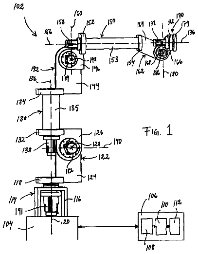
Modular robot arm joints
An industrial robot arm built from modules, each with two members that rotate about an axis.
US 9,827,640 B2 · Title as filed: Apparatus and a system for automatic tool change by threading engagement for a CNC milling machine · Inventors: Uriarte; Jorge
Sheet 1 of 6 from the published document. All sheets in the USPTO PDF
A collet that locks by threading, so a CNC or robot can swap tools automatically.
An apparatus and a system comprise a collet comprising a top portion and a bottom portion. The top portion comprises a threading means. The bottom portion at least comprises means for holding the collet from rotating and means for retaining an end mill. A master comprises a top portion and a bottom portion. The top portion is configured for engagement with a spindle of a milling machine. The bottom portion comprises a threading means for engagement with the threading means of the collet, wherein the master is retained by the spindle and the collet engages and disengages the master by rotation of the spindle. The milling machine operates under computer control during engagement and disengagement of the collet from the master.
The following background information may present examples of specific aspects of the prior art (e.g., without limitation, approaches, facts, or common wisdom) that, while expected to be helpful to further educate the reader as to additional aspects of the prior art, is not to be construed as limiting the present invention, or any embodiments thereof, to anything stated or implied therein or inferred thereupon. The following is an example of a specific aspect in the prior art that, while expected to be helpful to further educate the reader as to additional aspects of the prior art, is not to be construed as limiting the present invention, or any embodiments thereof, to anything stated or implied therein or inferred thereupon. By way of educational background, another aspect of the prior art generally useful to be aware of is that, the prior art discloses a collet arbor. In some instances,
The first 3 of 6 drawing sheets from the published document, cropped to the drawing. Every sheet is in the USPTO PDF.
Independent claims and the claims that build on them, read from each claim's text.
What the patent claimed, word for word. All of it is now free to use.
Not applicable. RELATED CO-PENDING U.S.
Not applicable.
Not applicable.
Not applicable.
A portion of the disclosure of this patent document contains material that is subject to copyright protection by the author thereof. The copyright owner has no objection to the facsimile reproduction by anyone of the patent document or patent disclosure for the purposes of referencing as patent prior art, as it appears in the Patent and Trademark Office, patent file or records, but otherwise reserves all copyright rights whatsoever.
One or more embodiments of the invention generally relate to automatic tool changing by threading engagement for a CNC Milling machine. More particularly, the invention relates to machine tooling functions for hole threading, or rigid tapping.
The following background information may present examples of specific aspects of the prior art (e.g., without limitation, approaches, facts, or common wisdom) that, while expected to be helpful to further educate the reader as to additional aspects of the prior art, is not to be construed as limiting the present invention, or any embodiments thereof, to anything stated or implied therein or inferred thereupon.
The following is an example of a specific aspect in the prior art that, while expected to be helpful to further educate the reader as to additional aspects of the prior art, is not to be construed as limiting the present invention, or any embodiments thereof, to anything stated or implied therein or inferred thereupon. By way of educational background, another aspect of the prior art generally useful to be aware of is that, the prior art discloses a collet arbor. In some instances, the prior art reflects an external perspective view of one form of an collet arbor, together with a collet of the 3AT type, by which the collet arbor is specifically adapted to accommodate. The collet arbor is a composite comprising the clamping holder, the adapter, and a bushing, which are assembled in coaxial relation together with an internal screw, to accommodate the collet. The means by which comprise an axially projecting screw, provided for securely coupling the collet arbor assemblage in axial relation to the spindle of a lathe. In alternative placements, this may take the form of a screw-threaded socket. The assemblage, including: collet, bushing, screw, adapter, and clamping holder, are fitted together in telescopic relation, forming a chuck or collet arbor for holding a tool, for example, in a fixed relation to a lathe, particularly of the computerized numerical controlled type, during turning operations. In some instances, four ¼ in. holes, which may be interposed through the wall of flange, at symmetrically-spaced positions, around its periphery, permit the adapter to be rotated by means of a spanner wrench.
In addition, the following is another example of a specific aspect in the prior art that, while expected to be helpful to further educate the reader as to additional aspects of the prior art, is not to be construed as limiting the present invention, or any embodiments thereof, to anything stated or implied therein or inferred thereupon. By way of educational background, another aspect of the prior art generally useful to be aware of is that, the prior art discloses a spindle and tool holder for a machine tool. Furthermore, a tool holder carrier turret plate may be secured to a shaft mounted in the head and may have a plurality of circularly spaced apertures with retaining rings therein, holding a plurality of tool holders. Each of the plurality of tool holders may hold a particular tool for a particular type of machining operation to be performed by that tool on the work piece. A rotary drive for the turret plate may be provided in the head, and may be capable of positioning any one of the tool holders under the coupling plug. A computer numerical controller may also be coupled to the drive motors for the X-Y axes carriages and for the tool holder turret to position the work piece and tool holders according to a programmed sequence predetermined for the necessary operations on the work piece. In addition to the foregoing, it is also well know to those skilled in the art, complex hardware similar to rotary turrets, and air or hydraulic forces may be applied to hold collets into the spindle. Means for doing and performing these functions are all known in the art.
In view of the foregoing, it is clear that these traditional techniques are not perfect and leave room for more optimal approaches.
The present invention is illustrated by way of example, and not by way of limitation, in the figures of the accompanying drawings and in which like reference numerals refer to similar elements and in which:
FIG. 1 a illustrates an exemplary milling machine spindle, in accordance with the prior art;
FIGS. 1 b , and 1 c illustrate various views of an exemplary threaded CNC automatic tool changing system, according to an embodiment of the present invention, where FIG. 1 b illustrates a front internal view of the CNC automatic threading tool changing system in an exemplary sectionalized position, and FIG. 1 c illustrates an automatic tool changing system in an exemplary sectionally detached position, in accordance with an embodiment of the present invention;
FIG. 2 a illustrates an exemplary CNC machine tooling system with tray holder, according to an embodiment of the present invention;
FIGS. 2 b and 2 c illustrate exemplary tool change methods, in accordance with the prior art;
FIG. 3 a illustrates an exemplary flow chart of a method for CNC automatic tool changing system, in accordance with an embodiment of the present invention;
FIG. 3 b illustrates an exemplary flow chart for an initial setup method, in accordance with an embodiment of the present invention;
FIG. 4 illustrates an software module architecture of an automatic tool changing system by threading engagement for a CNC Milling machine application depicting a conventional client/server communication system, in accordance with an embodiment of the present invention; and
FIG. 5 illustrates an exemplary general computer software module architecture of a system for automatic tool changing by threading engagement for a CNC Milling machine for a web-enabled/networked application platform by which a client/server system may be used, in accordance with an embodiment of the present invention.
Unless otherwise indicated illustrations in the figures are not necessarily drawn to scale.
The present invention is best understood by reference to the detailed figures and description set forth herein.
Embodiments of the invention are discussed below with reference to the Figures. However, those skilled in the art will readily appreciate that the detailed description given herein with respect to these figures is for explanatory purposes as the invention extends beyond these limited embodiments. For example, it should be appreciated that those skilled in the art will, in light of the teachings of the present invention, recognize a multiplicity of alternate and suitable approaches, depending upon the needs of the particular application, to implement the functionality of any given detail described herein, beyond the particular implementation choices in the following embodiments described and shown. That is, there are modifications and variations of the invention that are too numerous to be listed but that all fit within the scope of the invention. Also, singular words should be read as plural and vice versa and masculine as feminine and vice versa, where appropriate, and alternative embodiments do not necessarily imply that the two are mutually exclusive.
It is to be further understood that the present invention is not limited to the particular methodology, compounds, materials, manufacturing techniques, uses, and applications, described herein, as these may vary. It is also to be understood that the terminology used herein is used for the purpose of describing particular embodiments only, and is not intended to limit the scope of the present invention. It must be noted that as used herein and in the appended claims, the singular forms “a,” “an,” and “the” include the plural reference unless the context clearly dictates otherwise. Thus, for example, a reference to “an element” is a reference to one or more elements and includes equivalents thereof known to those skilled in the art. Similarly, for another example, a reference to “a step” or “a means” is a reference to one or more steps or means and may include sub-steps and subservient means. All conjunctions used are to be understood in the most inclusive sense possible. Thus, the word “or” should be understood as having the definition of a logical “or” rather than that of a logical “exclusive or” unless the context clearly necessitates otherwise. Structures described herein are to be understood also to refer to functional equivalents of such structures. Language that may be construed to express approximation should be so understood unless the context clearly dictates otherwise.
All words of approximation as used in the present disclosure and claims should be construed to mean “approximate,” rather than “perfect,” and may accordingly be employed as a meaningful modifier to any other word, specified parameter, quantity, quality, or concept. Words of approximation, include, yet are not limited to terms such as “substantial”, “nearly”, “almost”, “about”, “generally”, “largely”, “essentially”, “closely approximate”, etc.
As will be established in some detail below, is well settle law, as early as 1939, that words of approximation are not indefinite in the claims even when such limits are not defined or specified in the specification.
For example, see Ex parte Mallory, 52 USPQ 297, 297 (Pat. Off. Bd. App. 1941) where the court said “The examiner has held that most of the claims are inaccurate because apparently the laminar film will not be entirely eliminated. The claims specify that the film is “substantially” eliminated and for the intended purpose, it is believed that the slight portion of the film which may remain is negligible. We are of the view, therefore, that the claims may be regarded as sufficiently accurate.”
Note that claims need only “reasonably apprise those skilled in the art” as to their scope to satisfy the definiteness requirement. See Energy Absorption Sys., Inc. v. Roadway Safety Servs., Inc., Civ. App. 96-1264, slip op. at 10 (Fed. Cir. Jul. 3, 1997) (unpublished) Hybridtech v. Monoclonal Antibodies, Inc., 802 F.2d 1367, 1385, 231 USPQ 81, 94 (Fed. Cir. 1986), cert. denied, 480 U.S. 947 (1987). In addition, the use of modifiers in the claim, like “generally” and “substantial,” does not by itself render the claims indefinite. See Seattle Box Co. v. Industrial Crating & Packing, Inc., 731 F.2d 818, 828-29, 221 USPQ 568, 575-76 (Fed. Cir. 1984).
Moreover, the ordinary and customary meaning of terms like “substantially” includes “reasonably close to: nearly, almost, about”, connoting a term of approximation. See In re Frye, Appeal No. 2009-006013, 94 USPQ2d 1072, 1077, 2010 WL 889747 (B.P.A.I. 2010) Depending on its usage, the word “substantially” can denote either language of approximation or language of magnitude. Deering Precision Instruments, L.L.C. v. Vector Distribution Sys., Inc., 347 F.3d 1314, 1323 (Fed. Cir. 2003) (recognizing the “dual ordinary meaning of th[e] term [“substantially”] as connoting a term of approximation or a term of magnitude”). Here, when referring to the “substantially halfway” limitation, the Specification uses the word “approximately” as a substitute for the word “substantially” (Fact 4). (Fact 4). The ordinary meaning of “substantially halfway” is thus reasonably close to or nearly at the midpoint between the forward most point of the upper or outsole and the rearward most point of the upper or outsole.
Similarly, term ‘substantially’ is well recognize in case law to have the dual ordinary meaning of connoting a term of approximation or a term of magnitude. See Dana Corp. v. American Axle & Manufacturing, Inc., Civ. App. 04-1116, 2004 U.S. App. LEXIS 18265, *13-14 (Fed. Cir. Aug. 27, 2004) (unpublished). The term “substantially” is commonly used by claim drafters to indicate approximation. See Cordis Corp. v. Medtronic AVE Inc., 339 F.3d 1352, 1360 (Fed. Cir. 2003) (“The patents do not set out any numerical standard by which to determine whether the thickness of the wall surface is ‘substantially uniform.’ The term ‘substantially,’ as used in this context, denotes approximation. Thus, the walls must be of largely or approximately uniform thickness.”); see also Deering Precision Instruments, LLC v. Vector Distribution Sys., Inc., 347 F.3d 1314, 1322 (Fed. Cir. 2003); Epcon Gas Sys., Inc. v. Bauer Compressors, Inc., 279 F.3d 1022, 1031 (Fed. Cir. 2002). We find that the term “substantially” was used in just such a manner in the claims of the patents-in-suit: “substantially uniform wall thickness” denotes a wall thickness with approximate uniformity.
It should also be noted that such words of approximation as contemplated in the foregoing clearly limits the scope of claims such as saying ‘generally parallel’ such that the adverb ‘generally’ does not broaden the meaning of parallel. Accordingly, it is well settled that such words of approximation as contemplated in the foregoing (e.g., like the phrase ‘generally parallel’) envisions some amount of deviation from perfection (e.g., not exactly parallel), and that such words of approximation as contemplated in the foregoing are descriptive terms commonly used in patent claims to avoid a strict numerical boundary to the specified parameter. To the extent that the plain language of the claims relying on such words of approximation as contemplated in the foregoing are clear and un contradicted by anything in the written description herein or the figures thereof, it is improper to rely upon the present written description, the figures, or the prosecution history to add limitations to any of the claim of the present invention with respect to such words of approximation as contemplated in the foregoing. That is, under such circumstances, relying on the written description and prosecution history to reject the ordinary and customary meanings of the words themselves is impermissible. See, for example, Liquid Dynamics Corp. v. Vaughan Co., 355 F.3d 1361, 69 USPQ2d 1595, 1600-01 (Fed. Cir. 2004). The plain language of phrase 2 requires a “substantial helical flow.” The term “substantial” is a meaningful modifier implying “approximate,” rather than “perfect.” In Cordis Corp. v. Medtronic AVE, Inc., 339 F.3d 1352, 1361 (Fed. Cir. 2003), the district court imposed a precise numeric constraint on the term “substantially uniform thickness.” We noted that the proper interpretation of this term was “of largely or approximately uniform thickness” unless something in the prosecution history imposed the “clear and unmistakable disclaimer” needed for narrowing beyond this simple-language interpretation. Id. In Anchor Wall Systems v. Rockwood Retaining Walls, Inc., 340 F.3d 1298, 1311 (Fed. Cir. 2003)” Id. at 1311. Similarly, the plain language of claim 1 requires neither a perfectly helical flow nor a flow that returns precisely to the center after one rotation (a limitation that arises only as a logical consequence of requiring a perfectly helical flow).
The reader should appreciate that case law generally recognizes a dual ordinary meaning of such words of approximation, as contemplated in the foregoing, as connoting a term of approximation or a term of magnitude; e.g., see Deering Precision Instruments, L.L.C. v. Vector Distrib. Sys., Inc., 347 F.3d 1314, 68 USPQ2d 1716, 1721 (Fed. Cir. 2003), cert. denied, 124 S. Ct. 1426
where the court was asked to construe the meaning of the term “substantially” in a patent claim. Also see Epcon, 279 F.3d at 1031 (“The phrase ‘substantially constant’ denotes language of approximation, while the phrase ‘substantially below’ signifies language of magnitude, i.e., not insubstantial.”). Also, see, e.g., Epcon Gas Sys., Inc. v. Bauer Compressors, Inc., 279 F.3d 1022 (Fed. Cir. 2002) (construing the terms “substantially constant” and “substantially below”); Zodiac Pool Care, Inc. v. Hoffinger Indus., Inc., 206 F.3d 1408 (Fed. Cir. 2000) (construing the term “substantially inward”); York Prods., Inc. v. Cent. Tractor Farm & Family Ctr., 99 F.3d 1568 (Fed. Cir. 1996) (construing the term “substantially the entire height thereof”); Tex. Instruments Inc. v. Cypress Semiconductor Corp., 90 F.3d 1558 (Fed. Cir. 1996) (construing the term “substantially in the common plane”). In conducting their analysis, the court instructed to begin with the ordinary meaning of the claim terms to one of ordinary skill in the art. Prima Tek, 318 F.3d at 1148. Reference to dictionaries and our cases indicates that the term “substantially” has numerous ordinary meanings. As the district court stated, “substantially” can mean “significantly” or “considerably.” The term “substantially” can also mean “largely” or “essentially.” Webster's New 20th Century Dictionary 1817 (1983).
Words of approximation, as contemplated in the foregoing, may also be used in phrases establishing approximate ranges or limits, where the end points are inclusive and approximate, not perfect; e.g., see AK Steel Corp. v. Sollac, 344 F.3d 1234, 68 USPQ2d 1280, 1285 (Fed. Cir. 2003) where it where the court said [W]e conclude that the ordinary meaning of the phrase “up to about 10%” includes the “about 10%” endpoint. As pointed out by AK Steel, when an object of the preposition “up to” is nonnumeric, the most natural meaning is to exclude the object (e.g., painting the wall up to the door). On the other hand, as pointed out by Sollac, when the object is a numerical limit, the normal meaning is to include that upper numerical limit (e.g., counting up to ten, seating capacity for up to seven passengers). Because we have here a numerical limit —“about 10%”—the ordinary meaning is that that endpoint is included.
In the present specification and claims, a goal of employment of such words of approximation, as contemplated in the foregoing, is to avoid a strict numerical boundary to the modified specified parameter, as sanctioned by Pall Corp. v. Micron Separations, Inc., 66 F.3d 1211, 1217, 36 USPQ2d 1225, 1229 (Fed. Cir. 1995) where it states “It is well established that when the term “substantially” serves reasonably to describe the subject matter so that its scope would be understood by persons in the field of the invention, and to distinguish the claimed subject matter from the prior art, it is not indefinite.” Likewise see Verve LLC v. Crane Cams Inc., 311 F.3d 1116, 65 USPQ2d 1051, 1054 (Fed. Cir. 2002). Expressions such as “substantially” are used in patent documents when warranted by the nature of the invention, in order to accommodate the minor variations that may be appropriate to secure the invention. Such usage may well satisfy the charge to “particularly point out and distinctly claim” the invention, 35 U.S.C. §112, and indeed may be necessary in order to provide the inventor with the benefit of his invention. In Andrew Corp. v. Gabriel Elecs. Inc., 847 F.2d 819, 821-22, 6 USPQ2d 2010, 2013 (Fed. Cir. 1988) the court explained that usages such as “substantially equal” and “closely approximate” may serve to describe the invention with precision appropriate to the technology and without intruding on the prior art. The court again explained in Ecolab Inc. v. Envirochem, Inc., 264 F.3d 1358, 1367, 60 USPQ2d 1173, 1179 (Fed. Cir. 2001) that “like the term ‘about,’ the term ‘substantially’ is a descriptive term commonly used in patent claims to ‘avoid a strict numerical boundary to the specified parameter, see Ecolab Inc. v. Envirochem Inc., 264 F.3d 1358, 60 USPQ2d 1173, 1179 (Fed. Cir. 2001) where the court found that the use of the term “substantially” to modify the term “uniform” does not render this phrase so unclear such that there is no means by which to ascertain the claim scope.
Similarly, other courts have noted that like the term “about,” the term “substantially” is a descriptive term commonly used in patent claims to “avoid a strict numerical boundary to the specified parameter.”; e.g., see Pall Corp. v. Micron Seps., 66 F.3d 1211, 1217, 36 USPQ2d 1225, 1229 (Fed. Cir. 1995); see, e.g., Andrew Corp. v. Gabriel Elecs. Inc., 847 F.2d 819, 821-22, 6 USPQ2d 2010, 2013 (Fed. Cir. 1988) (noting that terms such as “approach each other,” “close to,” “substantially equal,” and “closely approximate” are ubiquitously used in patent claims and that such usages, when serving reasonably to describe the claimed subject matter to those of skill in the field of the invention, and to distinguish the claimed subject matter from the prior art, have been accepted in patent examination and upheld by the courts). In this case, “substantially” avoids the strict 100% nonuniformity boundary.
Indeed, the foregoing sanctioning of such words of approximation, as contemplated in the foregoing, has been established as early as 1939, see Ex parte Mallory, 52 USPQ 297, 297 (Pat. Off. Bd. App. 1941) where, for example, the court said “the claims specify that the film is “substantially” eliminated and for the intended purpose, it is believed that the slight portion of the film which may remain is negligible. We are of the view, therefore, that the claims may be regarded as sufficiently accurate.” Similarly, In re Hutchison, 104 F.2d 829, 42 USPQ 90, 93 (C.C.P.A. 1939) the court said “It is realized that “substantial distance” is a relative and somewhat indefinite term, or phrase, but terms and phrases of this character are not uncommon in patents in cases where, according to the art involved, the meaning can be determined with reasonable clearness.”
Hence, for at least the forgoing reason, Applicants submit that it is improper for any examiner to hold as indefinite any claims of the present patent that employ any words of approximation.
Unless defined otherwise, all technical and scientific terms used herein have the same meanings as commonly understood by one of ordinary skill in the art to which this invention belongs. Preferred methods, techniques, devices, and materials are described, although any methods, techniques, devices, or materials similar or equivalent to those described herein may be used in the practice or testing of the present invention. Structures described herein are to be understood also to refer to functional equivalents of such structures. The present invention will now be described in detail with reference to embodiments thereof as illustrated in the accompanying drawings.
From reading the present disclosure, other variations and modifications will be apparent to persons skilled in the art. Such variations and modifications may involve equivalent and other features which are already known in the art, and which may be used instead of or in addition to features already described herein.
Although Claims have been formulated in this Application to particular combinations of features, it should be understood that the scope of the disclosure of the present invention also includes any novel feature or any novel combination of features disclosed herein either explicitly or implicitly or any generalization thereof, whether or not it relates to the same invention as presently claimed in any Claim and whether or not it mitigates any or all of the same technical problems as does the present invention.
Features which are described in the context of separate embodiments may also be provided in combination in a single embodiment. Conversely, various features which are, for brevity, described in the context of a single embodiment, may also be provided separately or in any suitable subcombination. The Applicants hereby give notice that new Claims may be formulated to such features and/or combinations of such features during the prosecution of the present Application or of any further Application derived therefrom.
References to “one embodiment,” “an embodiment,” “example embodiment,” “various embodiments,” “some embodiments,” “embodiments of the invention,” etc., may indicate that the embodiment(s) of the invention so described may include a particular feature, structure, or characteristic, but not every possible embodiment of the invention necessarily includes the particular feature, structure, or characteristic. Further, repeated use of the phrase “in one embodiment,” or “in an exemplary embodiment,” “an embodiment,” do not necessarily refer to the same embodiment, although they may. Moreover, any use of phrases like “embodiments” in connection with “the invention” are never meant to characterize that all embodiments of the invention must include the particular feature, structure, or characteristic, and should instead be understood to mean “at least some embodiments of the invention” includes the stated particular feature, structure, or characteristic.
References to “user”, or any similar term, as used herein, may mean a human or non-human user thereof. Moreover, “user”, or any similar term, as used herein, unless expressly stipulated otherwise, is contemplated to mean users at any stage of the usage process, to include, without limitation, direct user(s), intermediate user(s), indirect user(s), and end user(s). The meaning of “user”, or any similar term, as used herein, should not be otherwise inferred or induced by any pattern(s) of description, embodiments, examples, or referenced prior-art that may (or may not) be provided in the present patent.
References to “end user”, or any similar term, as used herein, is generally intended to mean late stage user(s) as opposed to early stage user(s). Hence, it is contemplated that there may be a multiplicity of different types of “end user” near the end stage of the usage process. Where applicable, especially with respect to distribution channels of embodiments of the invention comprising consumed retail products/services thereof (as opposed to sellers/vendors or Original Equipment Manufacturers), examples of an “end user” may include, without limitation, a “consumer”, “buyer”, “customer”, “purchaser”, “shopper”, “enjoyer”, “viewer”, or individual person or non-human thing benefiting in any way, directly or indirectly, from use of or interaction, with some aspect of the present invention.
In some situations, some embodiments of the present invention may provide beneficial usage to more than one stage or type of usage in the foregoing usage process. In such cases where multiple embodiments targeting various stages of the usage process are described, references to “end user”, or any similar term, as used therein, are generally intended to not include the user that is the furthest removed, in the foregoing usage process, from the final user therein of an embodiment of the present invention.
Where applicable, especially with respect to retail distribution channels of embodiments of the invention, intermediate user(s) may include, without limitation, any individual person or non-human thing benefiting in any way, directly or indirectly, from use of, or interaction with, some aspect of the present invention with respect to selling, vending, Original Equipment Manufacturing, marketing, merchandising, distributing, service providing, and the like thereof.
References to “person”, “individual”, “human”, “a party”, “animal”, “creature”, or any similar term, as used herein, even if the context or particular embodiment implies living user, maker, or participant, it should be understood that such characterizations are sole by way of example, and not limitation, in that it is contemplated that any such usage, making, or participation by a living entity in connection with making, using, and/or participating, in any way, with embodiments of the present invention may be substituted by such similar performed by a suitably configured non-living entity, to include, without limitation, automated machines, robots, humanoids, computational systems, information processing systems, artificially intelligent systems, and the like. It is further contemplated that those skilled in the art will readily recognize the practical situations where such living makers, users, and/or participants with embodiments of the present invention may be in whole, or in part, replaced with such non-living makers, users, and/or participants with embodiments of the present invention. Likewise, when those skilled in the art identify such practical situations where such living makers, users, and/or participants with embodiments of the present invention may be in whole, or in part, replaced with such non-living makers, it will be readily apparent in light of the teachings of the present invention how to adapt the described embodiments to be suitable for such non-living makers, users, and/or participants with embodiments of the present invention. Thus, the invention is thus to also cover all such modifications, equivalents, and alternatives falling within the spirit and scope of such adaptations and modifications, at least in part, for such non-living entities.
Headings provided herein are for convenience and are not to be taken as limiting the disclosure in any way.
The enumerated listing of items does not imply that any or all of the items are mutually exclusive, unless expressly specified otherwise.
It is understood that the use of specific component, device and/or parameter names are for example only and not meant to imply any limitations on the invention. The invention may thus be implemented with different nomenclature/terminology utilized to describe the mechanisms/units/structures/components/devices/parameters herein, without limitation. Each term utilized herein is to be given its broadest interpretation given the context in which that term is utilized.
Terminology. The following paragraphs provide definitions and/or context for terms found in this disclosure (including the appended claims):
“Comprising.” This term is open-ended. As used in the appended claims, this term does not foreclose additional structure or steps. Consider a claim that recites: “A memory controller comprising a system cache . . . ” Such a claim does not foreclose the memory controller from including additional components (e.g., a memory channel unit, a switch).
“Configured To.” Various units, circuits, or other components may be described or claimed as “configured to” perform a task or tasks. In such contexts, “configured to” or “operable for” is used to connote structure by indicating that the mechanisms/units/circuits/components include structure (e.g., circuitry and/or mechanisms) that performs the task or tasks during operation. As such, the mechanisms/unit/circuit/component can be said to be configured to (or be operable) for perform(ing) the task even when the specified mechanisms/unit/circuit/component is not currently operational (e.g., is not on). The mechanisms/units/circuits/components used with the “configured to” or “operable for” language include hardware—for example, mechanisms, structures, electronics, circuits, memory storing program instructions executable to implement the operation, etc. Reciting that a mechanism/unit/circuit/component is “configured to” or “operable for” perform(ing) one or more tasks is expressly intended not to invoke 35 U.S.C. .sctn.112, sixth paragraph, for that mechanism/unit/circuit/component. “Configured to” may also include adapting a manufacturing process to fabricate devices or components that are adapted to implement or perform one or more tasks.
“Based On.” As used herein, this term is used to describe one or more factors that affect a determination. This term does not foreclose additional factors that may affect a determination. That is, a determination may be solely based on those factors or based, at least in part, on those factors. Consider the phrase “determine A based on B.” While B may be a factor that affects the determination of A, such a phrase does not foreclose the determination of A from also being based on C. In other instances, A may be determined based solely on B.
The terms “a”, “an” and “the” mean “one or more”, unless expressly specified otherwise.
Unless otherwise indicated, all numbers expressing conditions, concentrations, dimensions, and so forth used in the specification and claims are to be understood as being modified in all instances by the term “about.” Accordingly, unless indicated to the contrary, the numerical parameters set forth in the following specification and attached claims are approximations that may vary depending at least upon a specific analytical technique.
The term “comprising,” which is synonymous with “including,” “containing,” or “characterized by” is inclusive or open-ended and does not exclude additional, unrecited elements or method steps. “Comprising” is a term of art used in claim language which means that the named claim elements are essential, but other claim elements may be added and still form a construct within the scope of the claim.
As used herein, the phase “consisting of” excludes any element, step, or ingredient not specified in the claim. When the phrase “consists of” (or variations thereof) appears in a clause of the body of a claim, rather than immediately following the preamble, it limits only the element set forth in that clause; other elements are not excluded from the claim as a whole. As used herein, the phase “consisting essentially of” limits the scope of a claim to the specified elements or method steps, plus those that do not materially affect the basis and novel characteristic(s) of the claimed subject matter.
With respect to the terms “comprising,” “consisting of,” and “consisting essentially of,” where one of these three terms is used herein, the presently disclosed and claimed subject matter may include the use of either of the other two terms. Thus in some embodiments not otherwise explicitly recited, any instance of “comprising” may be replaced by “consisting of” or, alternatively, by “consisting essentially of.”
Devices or system modules that are in at least general communication with each other need not be in continuous communication with each other, unless expressly specified otherwise. In addition, devices or system modules that are in at least general communication with each other may communicate directly or indirectly through one or more intermediaries.
A description of an embodiment with several components in communication with each other does not imply that all such components are required. On the contrary a variety of optional components are described to illustrate the wide variety of possible embodiments of the present invention.
As is well known to those skilled in the art many careful considerations and compromises typically must be made when designing for the optimal manufacture of a commercial implementation any system, and in particular, the embodiments of the present invention. A commercial implementation in accordance with the spirit and teachings of the present invention may configured according to the needs of the particular application, whereby any aspect(s), feature(s), function(s), result(s), component(s), approach(es), or step(s) of the teachings related to any described embodiment of the present invention may be suitably omitted, included, adapted, mixed and matched, or improved and/or optimized by those skilled in the art, using their average skills and known techniques, to achieve the desired implementation that addresses the needs of the particular application.
In the following description and claims, the terms “coupled” and “connected,” along with their derivatives, may be used. It should be understood that these terms are not intended as synonyms for each other. Rather, in particular embodiments, “connected” may be used to indicate that two or more elements are in direct physical or electrical contact with each other. “Coupled” may mean that two or more elements are in direct physical or electrical contact. However, “coupled” may also mean that two or more elements are not in direct contact with each other, but yet still cooperate or interact with each other.
A “computer” may refer to one or more apparatus and/or one or more systems that are capable of accepting a structured input, processing the structured input according to prescribed rules, and producing results of the processing as output. Examples of a computer may include: a computer; a stationary and/or portable computer; a computer having a single processor, multiple processors, or multi-core processors, which may operate in parallel and/or not in parallel; a general purpose computer; a supercomputer; a mainframe; a super mini-computer; a mini-computer; a workstation; a micro-computer; a server; a client; an interactive television; a web appliance; a telecommunications device with internet access; a hybrid combination of a computer and an interactive television; a portable computer; a tablet personal computer (PC); a personal digital assistant (PDA); a portable telephone; application-specific hardware to emulate a computer and/or software, such as, for example, a digital signal processor (DSP), a field-programmable gate array (FPGA), an application specific integrated circuit (ASIC), an application specific instruction-set processor (ASIP), a chip, chips, a system on a chip, or a chip set; a data acquisition device; an optical computer; a quantum computer; a biological computer; and generally, an apparatus that may accept data, process data according to one or more stored software programs, generate results, and typically include input, output, storage, arithmetic, logic, and control units.
Those of skill in the art will appreciate that where appropriate, some embodiments of the disclosure may be practiced in network computing environments with many types of computer system configurations, including personal computers, hand-held devices, multi-processor systems, microprocessor-based or programmable consumer electronics, network PCs, minicomputers, mainframe computers, and the like. Where appropriate, embodiments may also be practiced in distributed computing environments where tasks are performed by local and remote processing devices that are linked (either by hardwired links, wireless links, or by a combination thereof) through a communications network. In a distributed computing environment, program modules may be located in both local and remote memory storage devices.
“Software” may refer to prescribed rules to operate a computer. Examples of software may include: code segments in one or more computer-readable languages; graphical and or/textual instructions; applets; pre-compiled code; interpreted code; compiled code; and computer programs.
The description continues in the full USPTO document.
Fees are due 3.5, 7.5 and 11.5 years after grant. This patent expired on November 28, 2025, so the fee marked "not paid" was the one that went unpaid.
APPARATUS AND A SYSTEM FOR AUTOMATIC TOOL CHANGE BY THREADING ENGAGEMENT FOR A CNC MILLING MACHINE
Filed Jun 2015 · published Dec 2016Apparatus and a system for automatic tool change by threading engagement for a CNC milling machine
Filed Jun 2015 · granted Nov 2017Earlier publications, parents and continuations. None of them can still be enforced, or this patent would not be listed.
Prior art cited by the examiner or applicant. Useful when you check your own idea for novelty.
Names, summaries, modern angles and build ratings are Patent Yard's editorial notes. Everything else on this page comes from the documents linked above.