 Lapsed, fee not paid8 drawings
Consumer Products · US 11,278,152 B2
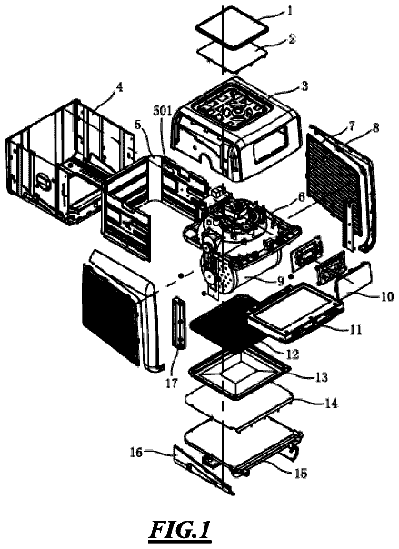
Rotisserie air-fryer oven
An air-fryer oven with a motorized rotating cage inside, so food tumbles in the hot air for even cooking.
US 6,500,043 B1 · Title as filed: Animated toy · Inventors: Fong; Peter Sui Lun
Sheet 1 of 8 from the published document. All sheets in the USPTO PDF
A toy figure with jointed legs, waist and arms, where a reversible motor tilts the legs back and forth and linked arms swing alternately.
An animated toy comprising a toy body which itself includes at least one shoulder member and a pair of waist members, the upper ends of which are pivotally connected to the shoulder member. The toy body further includes a pair of leg members having upper ends which are pivotally connected to the lower ends of respective ones of the leg members. The lower ends of the leg members are pivotally connected to respective ones of a pair of foot members. Rotatably connected to a shoulder member is a pair of arm members of the toy body which is mechanically coupled to the upper ends of respective ones of the waist members so as to be alternately moveable in different directions thereby. In addition to the toy body, the animated toy comprises a drive unit mounted to the toy body and including a reversible motor which is mechanically coupled to the leg members and operative to reciprocally tilt the leg members in first and second directions.
The present invention relates generally to motion toys, and more particularly to an animated toy comprising a plurality of structural elements pivotally connected to each other in a manner defining a human body, and a reversible motor which is cooperatively engaged to the structural elements and operative to cause portions of the body defined thereby to alternatively tilt or sway in different directions. There is currently known in the prior art a wide variety of animated or motion toys which employ the use of one or more motors and associated transmission gear trains to facilitate the movement of various parts of the toy. These animated toys include figurines which have the shape of a human body, with the motor(s) and gear train(s) thereof being operative to cause various parts of the body, such as the arms, legs and/or head, to move separately and/or in unison. One such animated or mot
The first 1 of 8 drawing sheets from the published document, cropped to the drawing. Every sheet is in the USPTO PDF.
Independent claims and the claims that build on them, read from each claim's text.
What the patent claimed, word for word. All of it is now free to use.
(Not Applicable)
(Not Applicable)
The present invention relates generally to motion toys, and more particularly to an animated toy comprising a plurality of structural elements pivotally connected to each other in a manner defining a human body, and a reversible motor which is cooperatively engaged to the structural elements and operative to cause portions of the body defined thereby to alternatively tilt or sway in different directions.
There is currently known in the prior art a wide variety of animated or motion toys which employ the use of one or more motors and associated transmission gear trains to facilitate the movement of various parts of the toy. These animated toys include figurines which have the shape of a human body, with the motor(s) and gear train(s) thereof being operative to cause various parts of the body, such as the arms, legs and/or head, to move separately and/or in unison.
One such animated or motion toy currently known in the prior art is disclosed in U.S. Pat. No. 5,911,617 issued on Jun. 15, 1999 to Chou. The motion toy disclosed in the Chou patent differs from those known in the prior art by, among other things, the capability of the upper and lower parts of the body thereof to alternatively tilt inwardly and outwardly in reverse directions. To achieve this particular range of motion, the motion toy disclosed in the Chou patent comprises a pair of waist cover shells, the upper ends of which are pivotally connected to respective ones of a pair of shoulder cover shells, with the lower ends of the waist cover shells being pivotally connected to respective ones of a pair of foot cover shells. Also included in the motion toy is a pair of trunk cover shells which are connected to respective ones of the shoulder cover shells and a motor mount which is mounted within a cavity collectively defined by the waist, shoulder and trunk cover shells. A reversible motor is attached to the motor mount and mechanically coupled to the foot cover shells via a pair of main racks which are integrally formed on respective ones of the foot cover shells.
Though the body of the motion toy disclosed in the Chou patent is uniquely configured in a manner wherein the upper and lower parts thereof alternatively tilt inwardly and outwardly in reverse directions, such motion toy possesses certain deficiencies which detract from its overall utility. These deficiencies include the inability of the upper and lower parts of the body to tilt or sway at differing speeds. In this respect, the reversible motor of the animated toy disclosed in the Chou patent operates at only a single speed or frequency, thus resulting in the speed or rate at which the upper and lower parts of the body tilt inwardly and outwardly being a constant during the operation of the motion toy. Additionally, the motion toy disclosed in the Chou patent is devoid of any structures which provide for the movement of the arms and head of the toy which are attached to the shoulder cover shells thereof. As will be recognized, such movement of the arms and/or head would provide a more life-like, appealing appearance during the operation of the motion toy. Moreover, the structures employed to facilitate the mechanical coupling of the reversible motor to the foot cover shells, and more particularly to the main racks thereof, creates an imbalance during operation which gives rise to a susceptibility for the motion toy to fall over onto one of its sides upon reaching the limits or extremes of its inward and outward movements. Indeed, in the commercially marketed embodiment of the motion toy disclosed in the Chou patent, the foot plates which are pivotally connected to the lower ends of respective ones of the foot cover shells are themselves attached to a common base plate for purposes of providing support to the motion toy and preventing the same from falling over due to the above-described imbalance condition.
The present invention provides an animated or motion toy similar in structure and operation to that disclosed in the Chou patent, but eliminating the above-described deficiencies. More particularly, the animated toy of the present invention is provided with an internal cam arrangement which facilitates the alternating upward and downward movement of the arms attached to the shoulder member of the body thereof. This cam arrangement also provides for the rotation of the head attached to the shoulder member in a back and forth motion. Additionally, unique electronic circuitry is provided in the animated toy of the present invention which is in electrical communication with the reversible motor thereof. This electronic circuitry is capable of operating the reversible motor at differing speeds, thus allowing for variations in the speed or rate of the swaying motion of the upper and lower portions of the body which are in time with the music played by the animated toy during its operation. Moreover, the animated toy of the present invention is provided with discrete rack members which are used to mechanically couple the reversible motor to the leg members in a manner maintaining the balance and stability of the present animated toy through its complete range of tilting movement, thus eliminating the need for additional support structures such as a base plate attached to the foot members thereof. These and other unique attributes of the present invention will be discussed in more detail below.
In accordance with the present invention, there is provided an animated toy which comprises a toy body. The toy body itself comprises a shoulder member and a pair of waist members, the upper ends of which are pivotally connected to the shoulder member. The toy body further comprises a pair of leg members, the upper ends of which are pivotally connected to the lower ends of respective ones of the waist members, and a pair of foot members which are pivotally connected the lower ends of respective ones of the leg members. In addition to the shoulder, waist, leg and foot members, the toy body includes a pair of arm members and a head member which are each rotatably connected to the shoulder member.
In addition to the toy body, the animated toy of the present invention comprises a drive unit which is mounted to the toy body and includes a reversible motor which is mechanically coupled to the leg members and operative to reciprocally tilt the leg members in first and second directions. The tilting of the leg members in the first and second directions occurs in unison. The drive unit preferably comprises a motor mount which is pivotally connected to the shoulder member and extends between the waist members. The reversible motor is itself preferably attached to the motor mount, with the tilting of the leg members in the first direction causing the motor mount to be tilted in the second direction, and the tilting of the leg members in the second direction causing the motor mount to be titled in the first direction.
In the present animated toy, the arm members of the toy body are mechanically coupled to the upper ends of respective ones of the waist members so as to be alternately movable in different directions thereby. More particularly, the mechanical coupling of the arm members to the waist members is accomplished such that the tilting of the waist members in the first and second directions causes the arm members to alternately move in different (i.e., opposite) directions. Similarly, the head member of the toy body is mechanically coupled to the motor mount such that the tilting of the motor mount in the first and second directions causes the head member to alternately rotate in different directions. The toy body may further include front and back trunk plates which are each attached to the motor mount and, together with the waist members and shoulder member, collectively define an interior cavity which accommodates the motor mount and hence the reversible motor.
To facilitate the alternating movement of the arm members, each of the waist members preferably includes a cam portion which defines the upper end thereof and has a slot formed therein Additionally, each of the arm members preferably includes an arm pin which protrudes therefrom and is received into the slot of a respective one of the cam portions. The tilting of the waist members in the first and second directions causes the cam portions to act against the arm pins in a manner facilitating the alternate rotation of the arm members in opposite directions.
To facilitate the alternate rotation of the head member, the motor mount preferably includes a pair of cam levers which protrude therefrom in spaced, generally parallel relation to each other. The head member itself defines a central axis and includes a head pin protruding therefrom in radially off-set relation to the central axis. When the head member is rotatably connected to the shoulder member, the head pin is extended between the cam levers such that the tilting of the motor mount in the first and second directions causes the cam levers to act against the head pin in a manner facilitating the alternate rotation of the head member in opposite directions.
The animated toy of the present invention may further comprise a variable speed control unit which is disposed within the toy body and in electrical communication with the reversible motor. The control unit is operative to selectively increase and decrease the speed of the reversible motor, and hence the rate at which the waist members are tilted in the first and second directions thereby. Also included in the animated toy of the present invention is a speaker which is mounted to the toy body, and a music unit which is disposed within the toy body and in electrical communication with the speaker and the control unit. The music unit is operative to produce music signals, with the control unit being operative to increase and decrease the speed of the reversible motor in time with the music signals produced by the music unit and transmitted to the speaker. Both the music unit and the control unit are preferably disposed within one of the foot members of the toy body.
The animated toy of the present invention may further comprise a pair of rack members which are rotatably connected to respective ones of the leg members, and each include a rack portion and a spring portion. The spring portion of each of the rack members is cooperatively engagable to a respective one of the leg members, with the tilting of the leg members in the first and second directions being limited by the alternate engagement of the spring portions of the rack members to respective ones of the leg members. Such engagement of the spring portions to the leg members occurs when the leg members reach the extreme limits of their tilting movement in the first and second directions, and prevents excess tilting as could result in the animated toy falling onto one of its sides. The dampening effect facilitated by the spring portions of the rack members may be complemented by a pair of dampening members which are attached to the motor mount and alternately engagable to the waist members during the tilting thereof in the first and second directions.
In accordance with an alternative embodiment of the present invention, the waist members of the toy body are pivotally connected to only the motor mount, and thus have no physical contact with the shoulder member. In this alternative embodiment, the motor mount is itself formed to include the cam portions, with such cam portions being mechanically coupled to respective ones of the arm members. As such, the back and forth tilting of the motor mount in the first and second directions results in the cam portions thereof acting against the arm pins of the arm members in a manner facilitating the alternate rotation of the arm members in opposite directions. BRIEF DESCRIPTION OF THE DRAWINGS These, as well as other features of the present invention, will become more apparent upon reference to the drawings wherein: FIG. 1 is a front prospective view of the animated toy of the present invention; FIG. 2 is a partial front prospective view of the present animated toy illustrating the movement capability of various portions thereof; FIG. 3 is a prospective view of the motor speed control unit of the animated toy shown in FIGS. 1 and 2; FIG. 4 is a circuit diagram for the motor speed control unit shown in FIG. 3; FIG. 5 is a front elevational, partial cross-sectional view of the present animated toy at one limit of its range of motion; FIG. 6 is a front elevational, partial cross-sectional view of the present animated toy similar to that shown in FIG. 5, but illustrating the opposite limit of its range of motion; FIG. 7 is a back elevational, partial cross-sectional view of the present animated toy at the limit of its range of motion shown in FIG. 5; FIG. 8 is an exploded view of the present animated toy, illustrating the various components thereof; and FIG. 9 is a rear elevational, partial cross-sectional view of an alternative embodiment of the present animated toy.
Referring now to the drawings when the showings are for purposes of illustrating a preferred embodiment of the present invention only, and not for purposes of limiting the same, FIG. 1 perspectively illustrates the animated toy 10 constructed in accordance with the present invention. As seen in FIG. 1, the animated toy 10 has the configuration of a human being, and more particularly Santa Claus. As will be discussed in more detail below, the animated toy 10 includes a head, torso, arms, legs and feet. Though being provided in the form of a human body, those of ordinary skill in the art will recognize that the animated toy 10 need not necessarily resemble Santa Claus.
Referring now to FIGS. 2 and 5-8, the animated toy 10 comprises a toy body 12 which itself comprises a shoulder member 14. In the preferred embodiment, the shoulder member 14 includes a front shoulder section 16 and a back shoulder section 18 which are rigidly attached to each other via fasteners such as screws. In addition to the shoulder member 14, the toy body 12 includes a pair of waist members 20, each of which defines an upper end 22 and a lower end 24. The upper ends 22 of the waist members 20 are pivotally connected to the shoulder member 14 via fasteners 23 such as a pair of pivot pins. The upper ends 22 of the waist members 20 are inserted between the front and back shoulder sections 16, 18, and more particularly into a cavity collectively defined thereby. Each fastener 23 is advanced through a respective upper end 22, with the opposed ends of such fastener 23 being received into a corresponding pair of tubular bosses formed on respective ones of the front and back shoulder sections 16, 18. As best seen in FIG. 7, in the preferred embodiment, the upper end 22 of each waist member 20 is defined by an arcuate cam portion 26 which includes a slot 28 formed therein. The use of the cam portion 26 and slot 28 of each waist member 20 will be discussed in more detail below.
The toy body 12 of the animated toy 10 further comprises a pair of leg members 30, each of which defines an upper end 32 and a lower end 34. Though not shown, the leg members 30 are preferably not unitary structures, but rather each comprise front and back leg sections 30a, 30b which are rigidly attached to each other via fasteners such as screws. In the animated toy 10, the upper ends 32 of the leg members 30 are pivotally connected to the lower ends 24 of respective ones of the waist members 20 via a pair of fasteners such as pivot pins 33. More particularly, as best seen in FIG. 2, the lower end 24 of each waist member 20 is inserted between a pair of ear portions defined at the upper end 32 of a respective leg member 30. One of these ear portions is formed on the front leg section 30a of the leg member 30, with the other ear portion being formed on the rear leg section 30b thereof. A pivot pin 33 is advanced through the lower end 24, with the opposed ends of the pivot pin 33 being received into and supported by a pair of tubular bosses formed on respective ones of the ear portions defining the corresponding upper end 32. The toy body 12 further comprises a pair of foot members 36 which are themselves pivotally connected to the lower ends 34 of respective ones of the leg members 30 via fasteners 35 such as pivot pins.
As best seen in FIGS. 5-7, protruding forwardly from the upper ends 32 of respective ones of the leg members 30 is a front pair of leg pins 70. Similarly, protruding rearwardly from the upper ends 32 of respective ones of the leg members 30 is a back pair of leg pins 72. More particularly, the leg pins 70 of the front pair protrude forwardly from the front leg sections 30a of respective ones of the leg members 30, with the leg pins 72 of the back pair protruding rearwardly from the back leg sections 30b of respective ones of the leg members 30. The use of the leg pins 70, 72 of the front and back pairs will be discussed in more detail below.
The toy body 12 of the animated toy 10 further comprises a pair of arm members 38 which are rotatably connected to respective ones of the opposed ends of the shoulder member 14 in the manner best shown in FIGS. 5-7. More particularly, each of the arm members 38 defines a continuous groove or channel 40 which extends thereabout in close proximity to the end thereof opposite the end formed to include the fingers. The channel 40 of each arm member 38 is sized and configured to receive a complimentary, continuous annular lip collectively defined by the front and back shoulder sections 16, 18 of the shoulder member 14, with the receipt of such lip into the channel 40 facilitating the rotatable attachment of the arm member 38 to the shoulder member 14. As will be recognized, to facilitate the receipt of each of the annular lips of the shoulder member 14 into a respective channel 40, the arm members 38 are positioned between the front and back shoulder sections 16, 18 in a prescribed manner prior to the rigid attachment thereof to each other.
As further seen in FIGS. 5-7, each of the arm members 38 includes an arm pin 42 protruding axially from the end thereof disposed closest to the channel 40. When the arm members 38 are rotatably connected to the shoulder member 14 in the above-described manner, the arm pins 42 thereof are inserted into the slots 28 of respective ones of the cam portions 26 of the waist members 20. The receipt of the arm pins 42 into the slots 28 allows the cam portions 26 to act against the arm pins 42 in a manner which facilitates the alternating upward and downward movement of the arm members 38 as will be discussed in more detail below.
Also rotatably connected to the shoulder member 14 is a head member 44 of the toy body 12. The head member 44 includes a stem section 46 which is itself rotatably connected to the shoulder member 14. More particularly, as best seen in FIG. 7, the stem section 46 defines a continuous groove or channel 48 which extends thereabout and is sized and configured to receive a complimentary annular edge collectively defined by the front and back shoulder sections 16, 18. This annular edge defines the periphery of a circular opening formed within the top of the shoulder member 14. The stem section 46 defines a central axis CA and, when rotatably connected to the shoulder member 14, is adapted to rotate about the central axis CA. Protruding from that end of the stem section 46 disposed closest to channel 48 is a head pin 50. In the toy body 12, the head pin 50 is not coaxially aligned with the central axis CA, but rather extends from the end of the stem section 46 in radially off-set relation to the central axis CA for reasons which will be described in more detail below. As such, the head pin 50, like the arm pins 42, resides within the interior of the shoulder member 14.
In addition to the stem section 46, the head member 44 includes a decorative outer section 52 which is attached to a generally conical end portion 54 of the stem section 46 located opposite the end including the head pin 50 protruding therefrom. Extending laterally from the end portion 54 is a locking tab 56 of the stem section 46. The attachment of the outer section 52 to the stem section 46 is facilitated by the insertion of the end portion 54 and locking tab 56 into a complimentary opening and associated slot formed within the outer section 52. The receipt of the locking tab 56 into its corresponding slot within the outer section 52 prevents the rotation of the outer section 52 relative to the stem section 46, thus ensuring that the outer section 52 rotates concurrently with the stem section 46. The head pin 50 protruding from the stem section 46 facilitates the rotation of the head member 44 in a manner 20 which will described in more detail below.
The toy body 12 of the animated toy 10 further comprises a lower support strut 58 having opposed ends which are pivotally connected to those pivot pins 33 used to facilitate the pivotal connection of the upper ends 32 of the leg members 30 to lower ends 24 of respective ones of the waist members 20. As such, the support strut 58 extends between the lower ends 24 of the waist members 20, as well as the upper ends 32 of the leg members 30. The pivot pins 33 used to pivotally connect the waist members 20 to the leg members 30 are advanced through a corresponding pair of apertures 59 disposed within respective ones of the opposed ends of the support strut 58. Also formed within the support strut 58 is a spaced pair of arcuate slots 60, the use of which will be discussed in more detail below.
In addition to the toy body 12, the animated toy of the present invention comprises a drive unit 62 which is mounted to the toy body 12 and operative to reciprocally tilt the leg members 30 in first and second directions in a manner which will be described in more detail below. The drive unit 62 itself preferably comprises a motor mount 64 having an upper end which is pivotally connected to the shoulder member 14 via a fastener 66 such as a pivot pin. Protruding from a common side of the upper end of the motor mount 64 in spaced, generally parallel relation to each other is a pair of cam levers 68. As best seen in FIG. 7, when the stem section 46 of the head member 44 is rotatably connected to the shoulder member 14, the head pin 50 is advanced between the cam lever 68 of the motor mount 64. As will also be discussed in more detail below, the cam levers 68 act against the head pin 50 in a manner which facilitates the alternate rotation of the head member 44.
As best seen in FIGS. 5-7, the drive unit 62 of the animated toy 10 further comprises a reversible motor 74 which is attached to the back side or surface of the motor mount 64. Extending from the reversible motor 74 is a drive shaft 76 which is advanced through the motor mount 64 and protrudes from the front side or surface thereof. As will be recognized, the reversible motor 74 is operative to selectively rotate the drive shaft 76 in either clockwise or counter-clockwise directions. As will be discussed in more detail below, this alternating clockwise and counter-clockwise rotation of the drive shaft 76 facilitates the tilting or swaying motion of the leg members 30 of the toy body 12.
In the animated toy 10 of the present invention, the reversible motor 74, and in particular the drive shaft 76 thereof, is mechanically coupled to the leg members 30 such that the rotation of the drive shaft 76 in clockwise and counter-clockwise directions facilitates the tilting or swaying of the leg members 30 in first and second directions (i.e., back and forth) in unison. To facilitate such mechanical coupling, the animated toy 10 of the present invention is provided with an identically configured pair of rack members 78 which are rotatably connected to respective ones of those pivot pins 33 used to facilitate the pivotal connection of the upper ends 32 of the leg members 30 to lower ends 24 of respective ones of the waist members 20. Each of the rack members 78 includes a rack portion 80 and an elongate, flexible/resilient spring portion 82. The rack members 78 are rotatably connected to their respective pivot pins 33 such that the rack portions 80 thereof are directed inwardly toward each other, with the spring portions 82 extending downwardly into the hollow interior of respective ones of the leg members 30. Formed on the distal end of each rack portion 80 is a gear rack, the use of which will be discussed in more detail below.
As best seen in FIG. 7, in addition to the rack and spring portions 80, 82, each of the rack members 78 further includes an elongate stem portion 81. When the rack members 78 are pivotally connected to the pivot pins used to facilitate the pivotal connection of the leg members 30 to the waist members 20, the stem portions 81 are extended or advanced through respective ones of the slots 60 of the support strut 58. The distal ends of the stem portions 81 are interconnected by a helical spring 83.
As best seen in FIGS. 5 and 6, each of the leg members 30 is formed to include an integral drive tab portion 84 within the hollow interior thereof. Formed within each drive tab portion 84 is a slot which is adapted to receive the spring portion 82 of a respective rack member 78. The locations of the drive tab portions 84 within the leg members 30 and the length of the spring portions 82 is such that when the rack members 78 are pivotally connected to respective ones of the pivot pins used to pivotally connect the leg members 30 to the waist members 20, the spring portions 82 of the rack members 78 are advanced through the slots of respective ones of the drive tab portions 84 in the manner shown in FIGS. 5 and 6. The advancement of the spring portions 82 through the slots of the drive tab portions 84 allows the rack members 78 to act against the leg members 30 in a manner facilitating the reciprocal tilting thereof in the first and second directions as will be discussed in more detail below.
In the animated toy 10, the reversible motor 74 is cooperatively engaged (i.e., mechanically coupled) to the rack members 78 via a transmission gear train of the drive unit 62. This transmission gear train preferably comprises a first drive member 86 which is attached to the distal end of the drive shaft 76 protruding from the front side or surface of the motor mount 64. In addition to the first drive member 86, the transmission gear train includes a second drive member 88 which is rotatably connected to the motor mount 64 via a pin. The second drive member 88 includes an integral first gear portion 90 of reduced diameter. The first drive member 86 is mechanically coupled to the second drive member 88 via a continuous transmission belt 92. In this respect, formed with the peripheral edge of both the first and second drive members 86, 88 is a continuous channel which accommodates the transmission belt 92.
The transmission gear train further comprises a first gear member 94 which is also rotatably connected to the motor mount 64 via a pin 95. The teeth formed on the peripheral edge of the first gear member 94 are cooperatively engaged to the teeth formed on the peripheral edge of the first gear portion 90 of the second drive member 88. The first gear member 94 is also formed to include an integral second gear portion 96 of reduced diameter. The transmission gear train also includes a second gear member 98 which is rotatably connected to the motor mount 64 via a pin 100. The teeth formed on the peripheral edge of the second gear member 98 are cooperatively engaged to the teeth formed on the peripheral edge of the second gear portion 96 of the first gear member 94. The second gear member 98 is itself formed to include an integral third gear portion 102 of reduced diameter. When the second gear member 98 is rotatably connected to the motor mount 96, the third gear portion 102 is extended between the rack portions 80 of the rack members 78, with the gear teeth formed on the peripheral edge of the third gear portion 102 being cooperatively engaged to the gear racks formed on the rack portions 80 of the rack members 78.
The toy body 12 of the animated toy 10 of the present invention further preferably comprises a front trunk plate 104 and a back trunk plate 106, each of which is attached to the motor mount 64 via fasteners such as screws. Importantly, the front trunk plate 104 is formed to include a plurality of tubular bosses 105 which protrude from the inner surface thereof. When the front trunk plate 104 is attached to the motor mount 64, two of these tubular bosses 105 receive respective ones of the leg pins 70 of the front pair. Another one of these tubular bosses receives the end of the pin 100 which protrudes from the second gear member 98 and is opposite that end received into the motor mount 64. The back trunk plate 106 is itself formed to include a pair of tubular bosses 107 which protrude from the inner surface thereof and, when the back trunk plate 106 is attached to the motor mount 64, receive respective ones of the leg pins 72 of the rear pair.
Referring now to FIGS. 1-3, the reversible motor 74 of the drive unit 72 is electrically connected via wires 108 to electronic circuitry 110 of the animated toy 100. The electronic circuitry 110 is preferably disposed within one of the hollow foot members 36 of the toy body 12. The electronic circuitry 110 includes a receptacle 112 which allows the electronic circuitry 110 to be placed into electrical communication with an external power supply through the use of an adapter 114 sized and configured to be releasably engagable to the receptacle 112. As will be recognized, the coupling of the adapter 114 to the receptacle 112 allows power from the external power supply to be communicated to the reversible motor 74 via the electronic circuitry 110.
Included in the electronic circuitry 110 of the animated toy 10 is a variable motor speed control unit or circuit 116 which is schematically illustrated in FIG. 4. The control unit 116 is in electrical communication with the reversible motor 74, and is operative to selectively increase and decrease the speed of the reversible motor 74 and hence the rate at which the leg members 30 (and thus the waist members 20) are tilted in the first and second directions thereby. Also included in the electronic circuitry 110 is a music unit or circuit which is electrically connected via a pair of wires 118 to a speaker 119 mounted to the inner surface of the front trunk plate 104. The front trunk plate 104 is preferably formed to include a plurality of openings 120 which allow sound waves generated by the speaker 119 to be transmitted to the exterior of the toy body 12. Upon the activation of the animated toy 10, the music unit is operative to produce music signals which, when transmitted to the speaker 119, produce sound waves corresponding to a particular song. It is contemplated that the music unit may also be operative to produce signals which, when transmitted to the speaker 119, result in spoken dialogue being produced thereby. Thus, the activation of the animated toy 10 may result in a particular song alone or in combination with spoken dialogue emanating therefrom. Included in the electronic circuitry 110 is a volume control which allows the volume of music/dialogue transmitted from the speaker 119 to be selectively increased or decreased via a volume control knob 120 which partially protrudes from the foot member 36.
Also included in the electronic circuitry 110 is a sensor or motion detector 122, a portion of which resides within an opening at the front of the foot member 36, thus allowing the sensor 122 to sense motion signals emanating from the front of the animated toy 10. The electronic circuitry 110 also includes a selector switch 123 which allows the animated toy 10 to be operated in three different modes as will be described below. The volume control knob 120 also serves as an on/off switch, with the rotation thereof in one direction beyond a certain threshold (typically corresponding to a minimum volume) deactivating the toy 10 by cutting off the flow of electricity from the external power supply to the electronic circuitry 110.
In the operation of the animated toy 10, the activation of the reversible motor 74 facilitates the rotation of the drive shaft 76 thereof in either a clockwise or counter-clockwise direction. The rotation of the drive shaft 76 facilitates the rotation of the first drive member 86, and hence the second drive member 88 via the transmission belt 92. Due to the meshing of the first gear portion 70 with first gear member 94, the meshing of the second gear portion 96 of the first gear member 94 with the second gear member 98, and the meshing of the third gear portion 102 of the second gear member 98 with the rack portions 80 of the rack members 78, the rotation of the drive shaft 76 is translated by the gear transmission train into the simultaneous rotation of the rack members 78.
More particularly, due to the manner in which the third gear portion 102 of the second gear member 98 is cooperatively engaged to the rack portions 80, the rotation of the third gear portion 102 in a clockwise direction (i.e., the rotation of the second gear member 98 in a clockwise direction) as viewed from the front of the animated toy 10 as shown in FIG. 5 will result in the concurrent rotation of the rack members 78 in counter-clockwise directions. Such counter-clockwise rotation of the rack members 78 causes the spring portions 82 thereof to act against the leg members 30 which results in the same being tilted in unison in the first direction (i.e., to the left) as viewed from the front of the animated toy 10 as shown in FIG. 5. Conversely, the rotation of the second gear member 98 and hence the third gear portion 102 in a counter-clockwise direction as viewed from the front of the animated toy 10 as shown in FIG. 6 results in the concurrent clockwise rotation of the rack members 78. Such clockwise rotation of the rack portions 80 causes the spring portions 82 to act against the leg members 30 which results in the same being tilted in unison in the second direction (i.e., to the right) as viewed from the front of the animated toy 10 as shown in FIG. 6.
As will be recognized, the direction of rotation of the third gear portion 102 of the second gear member 98 is dictated by the direction of rotation of the drive shaft 76 extending from the reversible motor 74. Thus, the operation of the reversible motor 74 so as to reverse the rotation of the drive shaft 76 at prescribed intervals results in the reciprocal movement or tilting of the leg members 30 in the first and second directions. As indicated above, the front and back trunk plates 104, 106 are each attached to the motor mount 64, and are cooperatively engaged to respective ones of the front and rear pairs of leg pins 70, 72. As a result, as is best seen in FIGS. 5-7, the movement or tilting of the leg members 30 in unison in the first direction (to the left) results in the concurrent or simultaneous movement or tilting of the motor mount 64 in the second direction (to the right). Conversely, the tilting of the leg members 30 in unison in the second direction (to the right) results in the simultaneous tilting of the motor mount 64 in the first direction (to the left).
As is further seen in FIGS. 5-7, integrally formed on opposite sides of the motor mount 64 is a pair of internally threaded tubular bosses 124 which receive two of the fasteners (i.e., screws) used to attach the front trunk plate 104 thereto. As the motor mount 64 tilts in the first and second directions, these bosses 124 act against corresponding camming surfaces formed on the waist members 20 as results in the concurrent or simultaneous movement or tilting of the waist members 20 in the same direction as the motor mount 64. In this respect, due to the waist members 20 being pivotally connected to both the leg members 30 and shoulder member 14, the tilting of the motor mount 64 in the second direction (to the right) results in the bosses 124 thereof acting against the waist members 20 in a manner which facilitates the simultaneous tilting of the waist members 20 in the second direction (to the right). Conversely, the tilting of the motor mount 64 in the first direction (to the left) results in the bosses 124 thereof acting against the waist members 20 in a manner facilitating the simultaneous tilting thereof in the second direction (to the left).
As previously explained, the head pin 50 of the head member 44 is extended between the cam levers 68 of the motor mount 64. Due to the head pin 50 being radially offset from the central axis CA of the stem section 46, the movement or tilting of the motor mount 64 in the first direction causes the cam levers 68 to act against the head pin 50 in a manner facilitating the rotation of the stem section 46, and hence the head member 44, in a first direction. Conversely, the tilting of the motor mount in the second direction causes the cam levers 68 to act against the head pin 50 in a manner resulting in the rotation of the head member 44 in a second direction opposite the first direction. Thus, the back and forth movement of the motor mount 64 in the first and second directions results in the alternate rotation of the head member 44 of the toy body 12 in opposite directions.
Similarly, due to the receipt of the arm pins 42 of the arm members 38 into the slots 28 of respective ones of the cam portions 26, the tilting of the waist members in the first and second directions results in the simultaneous rotation of the arm members 38 in opposite directions. For example, as viewed from the front of the animated toy 10 as shown in FIG. 5, the tilting of the waist members 20 in the second direction (to the right) results in the right arm member 38 being rotated upwardly while the left arm member 38 is simultaneously rotated downwardly. Conversely, the tilting of the waist members 20 in the first direction (to the left) as viewed from the front of the animated toy 10 as shown in FIG. 6 results in the left arm member 38 being rotated upwardly while the right arm member 38 is simultaneously rotated downwardly. Thus, the tilting of the leg members 30 in the first and second directions results in the alternate rotation of the arm members 38 in opposite directions.
The description continues in the full USPTO document.
Animated toy
Filed Dec 1999 · granted Dec 2002Earlier publications, parents and continuations. None of them can still be enforced, or this patent would not be listed.
Prior art cited by the examiner or applicant. Useful when you check your own idea for novelty.
Names, summaries, modern angles and build ratings are Patent Yard's editorial notes. Everything else on this page comes from the documents linked above.