 Lapsed, fee not paid8 drawings
Consumer Products · US 11,278,152 B2
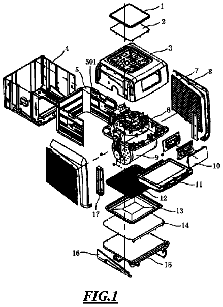
Rotisserie air-fryer oven
An air-fryer oven with a motorized rotating cage inside, so food tumbles in the hot air for even cooking.
US 6,401,952 B1 · Title as filed: Do-it-yourself modular article-holding container · Inventors: Ming; Chen Shan
Sheet 1 of 8 from the published document. All sheets in the USPTO PDF
A cylindrical container assembled from interlocking casing panels, a base, a seat ring and a rotating lid that locks into slots on the ring.
A modular container is formed of a casing, a seat ring, a rotary cover, and a base. The casing is provided with a plurality of retaining holes and retaining projections. The seat ring is located in the top of a cylindrical object which is formed by the casing. The base if disposed at the bottom of the cylindrical object. The rotary cover is provided with a plurality of retaining protrusions. The seat ring is provided with a plurality of locating slots. The rotary cover is located by the seat ring such that the retaining protrusions of the rotary cover are located in the locating slots of the seat ring.
The conventional stationery-holding containers are rather simple and monotonous in design. As a result, their marketability is limited.
The first 1 of 8 drawing sheets from the published document, cropped to the drawing. Every sheet is in the USPTO PDF.
Independent claims and the claims that build on them, read from each claim's text.
What the patent claimed, word for word. All of it is now free to use.
The present invention relates generally to a container, and more particularly to a do-it-yourself (DIY) modular container for holding stationery and the like.
The conventional stationery-holding containers are rather simple and monotonous in design. As a result, their marketability is limited.
The primary objective of the present invention is to provide a DIY modular container comprising a casing, a seat ring, a rotary cover, and a base, which can be arranged in a variety of ways by the consumer.
The objective, features, and functions of the present invention will be more readily understood upon a thoughtful deliberation of the following detailed description of the present invention with reference to the accompanying drawings. BRIEF DESCRIPTION OF THE SEVERAL VIEWS OF THE DRAWINGS FIG. 1 shows a perspective view of the present invention. FIG. 2 shows an exploded view of the present invention. FIG. 3 shows a sectional view of the present invention in combination. FIG. 4 shows a schematic view of the casing of the present invention that is spread out. FIG. 5 shows a schematic view of the present invention at work. FIG. 6 shows another schematic view of the present invention at work. FIG. 7 shows another schematic view of the present invention at work. FIG. 8 shows a schematic view of another preferred embodiment of the present invention.
As shown in all drawings provided herein, the present invention comprises a casing 10, a seat ring 20, a rotary cover 30, and a base 40.
The casing 10 is provided in one side with a plurality of retaining holes 11, and in other side with a plurality of retaining projections 12 corresponding in location to the retaining holes 11. The casing 10 can be rolled to form a cylindrical object such that the retaining projections 12 are retained in the retaining holes 11. The cylindrical object is provided in the top and the bottom with a plurality of through holes 13.
The seat ring 20 is provided with an annular slot 21 and an inverted hook 22. The seat ring 20 has an inner peripheral edge 23, which is provided with an annular protruded edge 24 and a plurality of locating slots 25.
The rotary cover 30 is provided in the top with a plurality of slotted edges 31, and in the periphery with a plurality of retaining protrusions 32, which are located in the locating slots 25 of the seat ring 20. The rotary cover 30 can be pressed downward and turned such that the rotary cover 30 is located in the seat ring 20, and that the top surface of the rotary cover 30 is level with the top edge of the seat ring 20.
The base 40 is used to seal off the bottom of the cylindrical object. The base 40 has an annular slot 41, which is provided with an inverted hook 42 engageable with the through hole 13.
The seat ring 20 and the base 40 are provided with a lug 50, and a strap 51 which is retained at both ends thereof by the lugs 50. The strap 51 is intended to facilitate the carrying of the cylindrical object.
The locating slots 25 of the seat ring 20 are formed of a vertically-oriented guide slot 251 and a horizontally oriented stop slot 252. The retaining protrusions 32 of the rotary cover 30 are slidably disposed in the guide slot 251 such that the retaining protrusions 32 of the rotary cover 30 are stopped by the stop slot 252 of the locating slots 25 of the seat ring 20.
The slotted edges 31 of the top of the rotary cover 30 have two upright walls and arcuate recesses.
The seat ring 20, the base 40, and the rotary cover 30 are round, tetragonal, or polygonal, as shown in FIGS. 6 and 7.
The seat ring 20 and the rotary cover 30 are provided with a plurality of retaining slots 60 and locating buttons 61. The locating buttons 61 are elastic and disposed in the fringe of the rotary cover 30. The locating buttons 61 are provided with a retaining projection 62, which is retained in the retaining slot 60 of the seat ring 20 and is provided with a control portion 63 for forcing the retaining projection 62 to move out of the retaining slot 60, so as to enable the rotary cover 30 to be removed form the seat ring 20, as shown in FIG. 8.
The present invention is versatile in design in that the present invention can be formed as a flat box, which can be shipped or mailed easily. In light of the top of the rotary cover 30 being level with the top edge of the seat ring 20, the rotary cover 30 can be easily removed by finger which is inserted in the slotted edge 31. However, the slotted edge 31 may be sealed off with adhesive tape or label to prevent the removal of the rotary cover 30 by an unauthorized person.
Do-it-yourself modular article-holding container
Filed Dec 2000 · granted Jun 2002DO-IT-YOURSELF MODULAR ARTICLE-HOLDING CONTAINER
Filed Dec 2000 · published Jul 2002Earlier publications, parents and continuations. None of them can still be enforced, or this patent would not be listed.
Prior art cited by the examiner or applicant. Useful when you check your own idea for novelty.
Names, summaries, modern angles and build ratings are Patent Yard's editorial notes. Everything else on this page comes from the documents linked above.