 Lapsed, fee not paid7 drawings
Tools & Workshop · US 8,678,185 B1
Slot-lid tool box
A tool box with side slots and a cover that slides and locks into them.
US 11,255,666 B1 · Title as filed: Level for use with drills · Inventors: O'Donnell; Michael
Sheet 1 of 7 from the published document. All sheets in the USPTO PDF
A level on an offset arm with a bearing around the bit, so it stays put while the bit spins and shows if you're straight.
A level that is attached to the drill bit. It is on a bar that allows the level to be offset from the drill bit so that it is visible by the operator. The bar has a bearing in it that allows the bit to spin freely while holding the level in a set position. The level has a ball that centers in a ring when it is level and plumb. To use the device, after it is installed in a drill, the operator adjusts the position of the drill until the ball is in the center of the ring. Then, the drill bit is plumb and the hold will be true. The operator merely has to watch the level and adjust the drill as needed to maintain plumb to ensure a true hole.
When drilling holes, for example, in concrete for anchors. It is important that the hole be plumb this is because rod installed in these holes must also be plumb or they will not align properly with other parts. It is possible to have a person hold a square or a small level to the side of a drill bit prior to drilling to check for plumb, while the drill is being held by another. It may even be possible to have that person remain in position during the drilling operation. This is, of course, impractical and potentially dangerous. It is also inefficient relying on two people do do the work. It is virtually impossible to hold a level adjacent to a drill bit, but it may be possible to position a speed square near the bit. That gives the drill operator a check of the plumb of the bit. But it is at best an inaccurate one.
The first 3 of 7 drawing sheets from the published document, cropped to the drawing. Every sheet is in the USPTO PDF.
Independent claims and the claims that build on them, read from each claim's text.
What the patent claimed, word for word. All of it is now free to use.
Not Applicable BACKGROUND OF THE INVENTION
This invention relates to levels for use with drills and particularly to levels that are viewed while a drill is in use.
When drilling holes, for example, in concrete for anchors. It is important that the hole be plumb this is because rod installed in these holes must also be plumb or they will not align properly with other parts. It is possible to have a person hold a square or a small level to the side of a drill bit prior to drilling to check for plumb, while the drill is being held by another. It may even be possible to have that person remain in position during the drilling operation. This is, of course, impractical and potentially dangerous. It is also inefficient relying on two people do do the work. It is virtually impossible to hold a level adjacent to a drill bit, but it may be possible to position a speed square near the bit. That gives the drill operator a check of the plumb of the bit. But it is at best an inaccurate one.
The instant invention provides a solution to this problem. It is a level that is attached to the drill bit. It is on a bar that allows the level to be offset from the drill bit so that it is visible by the operator. The bar has a bearing in it that allows the bit to spin freely while holding the level in a set position. The level has a ball that centers in a ring when it is level and plumb. To use the device, after it is installed in a drill, the operator adjusts the position of the drill until the ball is in the center of the ring. Then, the drill bit is plumb and the hold will be true. The operator merely has to watch the level and adjust the drill as needed to maintain plumb to ensure a true hole.
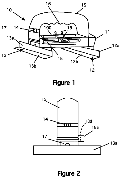
FIG. 1 a side perspective view of a drill showing the invention installed.
FIG. 1 a is a perspective view of a rotary hammer drill with the invention installed and the depth rod passing through the slot in the invention.
FIG. 2 is a top perspective view of the invention installed on a drill.
FIG. 3 is a top view of of the level device.
FIG. 4 is a side view of the level device.
FIG. 5 is a side detail view of the level installed on a drill bit.
FIG. 6 is a side perspective view of the level device.
FIG. 7 is a bottom view of the level device.
FIG. 8 is a detail view of the level component of the device that shows the bubble centered in the ring.
Referring now to the drawings, FIG. 1 , a side perspective view of a drill showing the invention installed is shown. The invention 10 is shown in a drill 105 mounted on a bit 100 as shown. Note how the device 10 is butted up against the chuck of the drill. A bearing in the device allows the bit to turn freely while the device stays in a fixed position. Note that the invention can be used with rotary hammer drills, or with conventional drills, as desired or as conditions necessitate.
FIG. 1 a is a perspective view of a rotary hammer drill with the invention installed and the depth rod passing through the slot in the invention. In this view, the depth rod 120 is shown. These rods are commonly provided on these drills to st a depth limit for the drill. Note that the invention 10 has a slot 13 a (see FIG. 7 , e. g.) through which the depth rod passes. The depth rod 120 rod helps hold the device in position during use, as discussed below.
FIG. 2 is a top perspective view of the invention installed on a drill showing the view of an operator 110 viewing the drill and the invention. When the drill is plumb with the surface to be drilled, the operator can proceed to drill. This figure shows how an operator actually uses the device. By holding the drill vertically, with the bit on the surface to be drilled, the user looks at the level 10 until the bubble 16 is centered in the ring, as discussed below. Once the bubble is centered, the drill 105 is plumb and the hole can be drilled. As the hole progresses, the user can monitor the level to ensure that the hole remains true. Note, in this view, the depth rod 120 is omitted to better show the invention.
FIG. 3 is a top view of the level device 10 . The device consists of a mounting section 11 that connects to a drill bit (see, FIG. 5 ). It has a bearing 12 that allows the bit to rotate without spinning the level 10 . A bar 13 connects the attachment piece 11 to the level 14 . The bar is used to offset the level component to the side so that it is visible to the user, (see, FIGS. 1 and 2 ). The level 14 is a circular bubble level. See FIG. 8 . It has a bubble 16 that floats within the body of the level 15 and indicates level and plumb so that when the bubble is completely centered in the level 14 , the drill is plumb to the surface and the hole made by it will be true.
FIG. 4 is a side view of the level 10 . The mounting section 11 , the bar 13 and the level 14 are shown.
FIG. 5 is side a detail view of the level 10 installed on a drill bit 100 . The device is designed to be held in place by inserting the bit 100 upwardly through the bearing 12 until the the the bit shaft 101 contacts the chuck of the drill. Since the bearing is smaller than the cutting flutes 102 of the bit, it cannot fall off. Friction holds the device in place and the bearing allows it to remain in place while the drill turns. Also, as discussed below, the depth rod 120 (see FIG. 1 a ), which is found on every rotary hammer type drill, can be extended through the slot 13 a to help hold the device in position.
FIG. 6 is a side perspective view of the level device. Here, the level 14 is shown on the surface of the bar 13 . Note too, the bearing 12 in the mounting section 11 .
FIG. 7 is a bottom view of the invention. Here, the bearing 12 is clearly shown inside the mounting section 11 . The level, being mounted on the top of the bar 13 cannot be seen from the bottom. Note that there is a slot 13 a cut into the bar 13 to accept a depth rod (see FIG. 1 a ), which helps hold the device in position and keeps it from rotating during use.
FIG. 8 is a detail of the level 14 showing the ring 15 and the bubble 16 . Note that the level 14 is a clear housing containing fluid. Within the fluid is the bubble 16 . The ring 15 is painted or printed on the top of the housing as shown. When the level is level, the bubble is centered in the housing and is contained within the ring when viewing from above.
The present disclosure should not be construed in any limited sense other than that limited by the scope of the claims having regard to the teachings herein and the prior art being apparent with the preferred form of the invention disclosed herein and which reveals details of structure of a preferred form necessary for a better understanding of the invention and may be subject to change by skilled persons within the scope of the invention without departing from the concept thereof.
Fees are due 3.5, 7.5 and 11.5 years after grant. This patent expired on February 22, 2026, so the fee marked "not paid" was the one that went unpaid.
Level for use with drills
Filed Feb 2019 · granted Feb 2022Earlier publications, parents and continuations. None of them can still be enforced, or this patent would not be listed.
Prior art cited by the examiner or applicant. Useful when you check your own idea for novelty.
Names, summaries, modern angles and build ratings are Patent Yard's editorial notes. Everything else on this page comes from the documents linked above.