 Lapsed, fee not paid4 drawings
Robotics & Automation · US 8,677,854 B2
Modular robot arm joints
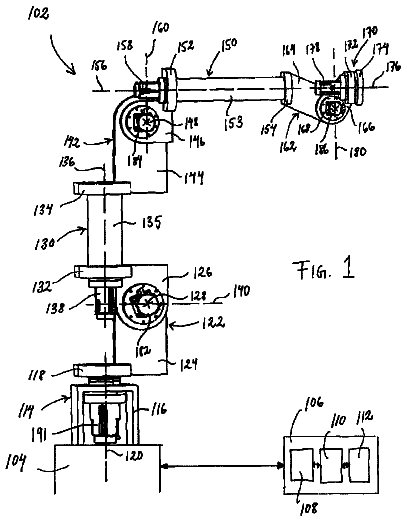
An industrial robot arm built from modules, each with two members that rotate about an axis.
US 11,207,776 B2 · Title as filed: Device, system, method, and machine-readable medium for conveying an industrial robot · Assignee: Siemens Ltd., China · Inventors: He; Jun Hu et al.
Sheet 1 of 7 from the published document. All sheets in the USPTO PDF
Automated carts carry industrial robots between workstations and lock them to magnetic bases on arrival.
A system for conveying an industrial robot includes: a control module, at least one automatic guided vehicle, and at least one electromagnetic base. An industrial robot is installed each electromagnetic base, which may attract a metallic plate fixed to the ground, thereby fixing the industrial robot installed on the electromagnetic base. An electromagnetic base is configured to, according to a first control instruction sent by the control module, stop attracting the metallic plate so that the industrial robot is movable. An automatic guided vehicle is configured to, according to a second control instruction sent by the control module, convey, to a target position, the industrial robot installed on the electromagnetic base that has stopped attracting the metallic plate. Finally, an electromagnetic base is further configured to, according to a third control instruction sent by the control module, attract the metallic plate fixed to the ground in the target position.
An industrial robot is a machine device having an articulated manipulator or multiple degrees of freedom that is applicable to industrial fields, capable of performing various jobs by its own power and control ability. A plurality of adjustable industrial robots may be connected and fitted with an automatic conveying device to assemble a flexible production line. A flexible production line may be managed by a computer and combine a plurality of production modes, thereby achieving the purpose of reducing production costs. Industrial robots included in a flexible production line are movable to restructure the flexible production line, so that various types of products may be produced. Generally, industrial robots included in a flexible production line in a factory are fixed by bolts to the ground. When an industrial robot is to be moved, first the bolts used to fix the industrial robot are
The first 3 of 7 drawing sheets from the published document, cropped to the drawing. Every sheet is in the USPTO PDF.
Independent claims and the claims that build on them, read from each claim's text.
What the patent claimed, word for word. All of it is now free to use.
The present application hereby claims priority under 35 U.S.C. § 119 to Chinese patent application number CN 201811151179.5 filed Sep. 29, 2018, the entire contents of which are hereby incorporated herein by reference.
Embodiments of the invention generally relate to the technical field of industrial production, in particular to a device, system, method, and machine-readable medium for conveying an industrial robot.
An industrial robot is a machine device having an articulated manipulator or multiple degrees of freedom that is applicable to industrial fields, capable of performing various jobs by its own power and control ability. A plurality of adjustable industrial robots may be connected and fitted with an automatic conveying device to assemble a flexible production line. A flexible production line may be managed by a computer and combine a plurality of production modes, thereby achieving the purpose of reducing production costs.
Industrial robots included in a flexible production line are movable to restructure the flexible production line, so that various types of products may be produced.
Generally, industrial robots included in a flexible production line in a factory are fixed by bolts to the ground. When an industrial robot is to be moved, first the bolts used to fix the industrial robot are removed manually, then the industrial robot is conveyed to a target position by manually driving a crane or fork-lift truck, and finally the industrial robot is fixed again manually.
Accordingly, the inventors have recognized that all the steps of conveying an industrial robot need to be completed manually, and consequently the efficiency of conveying an industrial robot is low.
In order to improve upon or even solve the aforesaid problem, a device, system, method, and machine-readable medium for conveying an industrial robot provided by the present invention can improve the efficiency of conveying an industrial robot.
In one aspect, an embodiment of the present invention provides a system for conveying an industrial robot, in which an industrial robot is installed on each electromagnetic base, and an electromagnetic base may attract a metallic plate fixed to the ground to fix the industrial robot installed on the electromagnetic base. When an industrial robot is to be conveyed, a control module may send a first control instruction to the electromagnetic base on which the industrial robot is installed; the electromagnetic base, according to the first control instruction received, stops attracting the metallic plate so that the industrial robot is movable; then, the control module sends a second control instruction to an automatic guided vehicle; the automatic guided vehicle, according to the second control instruction received, conveys, to a target position, the industrial robot and the electromagnetic base on which the industrial robot is installed; then, the control module sends a third control instruction to the electromagnetic base conveyed to the target position; and the electromagnetic base, according to the third control instruction received, attracts the metallic plate fixed to the ground in the target position, thereby fixing the industrial robot.
In a second aspect, an embodiment of the present invention further provides a robot conveying method, comprising: sending a first control instruction to an electromagnetic base, wherein the first control instruction is configured to instruct the electromagnetic base to stop attracting a metallic plate fixed to the ground so that the industrial robot installed on the electromagnetic base is movable; sending a second control instruction to an automatic guided vehicle, wherein the second control instruction is configured to instruct the automatic guided vehicle to convey, to a target position, the industrial robot installed on the electromagnetic base that has stopped attracting the metallic plate; and sending a third control instruction to an electromagnetic base, wherein the third control instruction is configured to instruct the electromagnetic base to attract a metallic plate fixed to the ground in the target position so that the industrial robot installed on the electromagnetic base is fixed.
In a third aspect, an embodiment of the present invention further provides another robot conveying method, comprising: receiving a first control instruction sent by the control module; instructing, according to the first control instruction, an electromagnetic attracting mechanism of an electromagnetic base on which an industrial robot is installed to stop attracting a metallic plate fixed to the ground; receiving a third control instruction sent by the control module; and instructing, according to the third control instruction, the electromagnetic attracting mechanism to attract a metallic plate fixed to the ground in a target position.
In a fourth aspect, an embodiment of the present invention further provides another robot conveying method, comprising: receiving a second control instruction sent by the control module; and instructing, according to the second control instruction, a conveying mechanism of an automatic guided vehicle to convey, to a target position, the industrial robot installed on the electromagnetic base that has stopped attracting the metallic plate.
In a fifth aspect, an embodiment of the present invention further provides a control module, comprising: a first instruction sending unit, configured to send a first control instruction to an electromagnetic base, wherein the first control instruction is configured to instruct the electromagnetic base to stop attracting a metallic plate fixed to the ground so that the industrial robot installed on the electromagnetic base is movable; and a second instruction sending unit, configured to send a second control instruction to an automatic guided vehicle, wherein the second control instruction is configured to instruct the automatic guided vehicle to convey, to a target position, the industrial robot installed on the electromagnetic base that has stopped attracting the metallic plate; and the first instruction sending unit is further configured to send a third control instruction to the electromagnetic base, wherein the third control instruction is configured to instruct the electromagnetic base to attract the metallic plate fixed to the ground in the target position, thereby fixing the industrial robot installed on the electromagnetic base.
In a sixth aspect, an embodiment of the present invention further provides an electromagnetic base, comprising: a first instruction receiving module, configured to receive a first control instruction from the control module, and an electromagnetic attracting mechanism, configured to, according to the first control instruction received by the first instruction receiving module, stop attracting a metallic plate fixed to the ground, wherein the first instruction receiving module is further configured to receive a third control instruction from the control module, and the electromagnetic attracting mechanism is further configured to, according to the third control instruction received by the first instruction receiving module, attract a metallic plate fixed to the ground in a target position.
In a seventh aspect, an embodiment of the present invention further provides an automatic guided vehicle, comprising: a second instruction receiving module, configured to receive a second control instruction from the control module, and a conveying mechanism, configured to, according to the second control instruction received by the second instruction receiving module, convey, to a target position, an industrial robot installed on an electromagnetic base that has stopped attracting a metallic plate.
In an eighth aspect, an embodiment of the present invention further provides another control module, comprising: at least one memory and at least one processor, wherein the at least one memory is configured to store a machine-readable program, and the at least one processor is configured to call the machine-readable program for implementing any one of the methods for conveying an industrial robot provided in the above-described second aspect.
In a ninth aspect, an embodiment of the present invention further provides another electromagnetic base, comprising: at least one memory and at least one processor, wherein the at least one memory is configured to store a machine-readable program, and the at least one processor is configured to call the machine-readable program for implementing any one of the methods for conveying an industrial robot provided in the above-described third aspect.
In a tenth aspect, an embodiment of the present invention further provides another automatic guided vehicle, comprising: at least one memory and at least one processor, wherein the at least one memory is configured to store a machine-readable program, and the at least one processor is configured to call the machine-readable program for implementing any one of the methods for conveying an industrial robot provided in the above-described fourth aspect.
In an eleventh aspect, an embodiment of the present invention further provides a machine-readable medium storing a computer instruction that, when executed by a processor, causes the processor to implement the method provided in the above-described second aspect or in any possible implementation mode of the second aspect.
FIG. 1 is a schematic diagram for a system for conveying an industrial robot provided in an embodiment of the present invention;
FIG. 2 is a schematic diagram for an electromagnetic base provided in an embodiment of the present invention;
FIG. 3 is a schematic diagram for another electromagnetic base provided in an embodiment of the present invention;
FIG. 4 is a schematic diagram for an automatic guided vehicle provided in an embodiment of the present invention;
FIG. 5 is a schematic diagram for another automatic guided vehicle provided in an embodiment of the present invention;
FIG. 6 is a flowchart for a method for conveying an industrial robot provided in an embodiment of the present invention;
FIG. 7 is a flowchart for another method for conveying an industrial robot provided in an embodiment of the present invention;
FIG. 8 is a flowchart for yet another method for conveying an industrial robot provided in an embodiment of the present invention;
FIG. 9 is a schematic diagram for a control module provided in an embodiment of the present invention;
FIG. 10 is a schematic diagram for another control module provided in an embodiment of the present invention;
FIG. 11 is a schematic diagram for yet another electromagnetic base provided in an embodiment of the present invention;
FIG. 12 is a schematic diagram for yet another automatic guided vehicle provided in an embodiment of the present invention;
FIG. 13 is a schematic diagram for yet another control module provided in an embodiment of the present invention;
FIG. 14 is a schematic diagram for still another electromagnetic base provided in an embodiment of the present invention;
FIG. 15 is a schematic diagram for still another automatic guided vehicle provided in an embodiment of the present invention;
FIG. 16 is a flowchart for still another method for conveying an industrial robot provided in an embodiment of the present invention; and
FIG. 17 is a schematic diagram for the process of conveying an industrial robot provided in an embodiment of the present invention.
TABLE-US-00001 10: Control module 20: Automatic 30: Electromagnetic guided vehicle base 40: Industrial robot 50: Metallic plate 60: New production line 101: First instruction 102: Second 103: Instruction sending unit instruction generating unit sending unit 201: Vehicle frame 202: Grab 203: Lifting mechanism mechanism 204: Wheel 205: Second 206: Conveying instruction mechanism receiving module 207: Memory 208: Processor 301: Case 302: Control panel 303: Magnetic 304: Power connector suction cup 305: First instruction 306: 307: Memory receiving module Electromagnetic attracting mechanism 308: Processor 2011: Wheel 2012: Gripper connecting connecting portion portion 2031: Linear driver 2032: Lifting 20321: First component connecting rod 20322: Second 501: Power connecting rod interface 601: Send a first control instruction to an electromagnetic base. 602: Send a second control instruction to an automatic guided vehicle. 603: Send a third control instruction to the electromagnetic base conveyed to the target position. 701: Receive a first control instruction sent by the control module. 702: According to the first control instruction, attract the metallic plate fixed to the ground. 703: Receive a third control instruction sent by the control module. 704: According to the third control instruction, attract the metallic plate fixed to the ground in the target position. 801: Receive a second control instruction sent by the control module. 802: According to the second control instruction, convey, to a target position, the industrial robot installed on the electromagnetic base. 901: The control module receives a conveyance instruction to convey the industrial robot. 902: The control module sends a fourth control instruction to an automatic guided vehicle. 903: The control module sends a first control instruction to the electromagnetic base on which the industrial robot is installed. 904: The control module sends a second control instruction to the automatic guided vehicle. 905: The control module sends a third control instruction to the electromagnetic base.
The drawings are to be regarded as being schematic representations and elements illustrated in the drawings are not necessarily shown to scale. Rather, the various elements are represented such that their function and general purpose become apparent to a person skilled in the art. Any connection or coupling between functional blocks, devices, components, or other physical or functional units shown in the drawings or described herein may also be implemented by an indirect connection or coupling. A coupling between components may also be established over a wireless connection. Functional blocks may be implemented in hardware, firmware, software, or a combination thereof.
Various example embodiments will now be described more fully with reference to the accompanying drawings in which only some example embodiments are shown. Specific structural and functional details disclosed herein are merely representative for purposes of describing example embodiments. Example embodiments, however, may be embodied in various different forms, and should not be construed as being limited to only the illustrated embodiments. Rather, the illustrated embodiments are provided as examples so that this disclosure will be thorough and complete, and will fully convey the concepts of this disclosure to those skilled in the art. Accordingly, known processes, elements, and techniques, may not be described with respect to some example embodiments. Unless otherwise noted, like reference characters denote like elements throughout the attached drawings and written description, and thus descriptions will not be repeated. The present invention, however, may be embodied in many alternate forms and should not be construed as limited to only the example embodiments set forth herein.
It will be understood that, although the terms first, second, etc. may be used herein to describe various elements, components, regions, layers, and/or sections, these elements, components, regions, layers, and/or sections, should not be limited by these terms. These terms are only used to distinguish one element from another. For example, a first element could be termed a second element, and, similarly, a second element could be termed a first element, without departing from the scope of example embodiments of the present invention. As used herein, the term “and/or,” includes any and all combinations of one or more of the associated listed items. The phrase “at least one of” has the same meaning as “and/or”.
Spatially relative terms, such as “beneath,” “below,” “lower,” “under,” “above,” “upper,” and the like, may be used herein for ease of description to describe one element or feature's relationship to another element (s) or feature (s) as illustrated in the figures. It will be understood that the spatially relative terms are intended to encompass different orientations of the device in use or operation in addition to the orientation depicted in the figures. For example, if the device in the figures is turned over, elements described as “below,” “beneath,” or “under,” other elements or features would then be oriented “above” the other elements or features. Thus, the example terms “below” and “under” may encompass both an orientation of above and below. The device may be otherwise oriented (rotated 90 degrees or at other orientations) and the spatially relative descriptors used herein interpreted accordingly. In addition, when an element is referred to as being “between” two elements, the element may be the only element between the two elements, or one or more other intervening elements may be present.
Spatial and functional relationships between elements (for example, between modules) are described using various terms, including “connected,” “engaged,” “interfaced,” and “coupled.” Unless explicitly described as being “direct,” when a relationship between first and second elements is described in the above disclosure, that relationship encompasses a direct relationship where no other intervening elements are present between the first and second elements, and also an indirect relationship where one or more intervening elements are present (either spatially or functionally) between the first and second elements. In contrast, when an element is referred to as being “directly” connected, engaged, interfaced, or coupled to another element, there are no intervening elements present. Other words used to describe the relationship between elements should be interpreted in a like fashion (e.g., “between,” versus “directly between,” “adjacent,” versus “directly adjacent,” etc.).
The terminology used herein is for the purpose of describing particular embodiments only and is not intended to be limiting of example embodiments of the invention. As used herein, the singular forms “a,” “an,” and “the,” are intended to include the plural forms as well, unless the context clearly indicates otherwise. As used herein, the terms “and/or” and “at least one of” include any and all combinations of one or more of the associated listed items. It will be further understood that the terms “comprises,” “comprising,” “includes,” and/or “including,” when used herein, specify the presence of stated features, integers, steps, operations, elements, and/or components, but do not preclude the presence or addition of one or more other features, integers, steps, operations, elements, components, and/or groups thereof. As used herein, the term “and/or” includes any and all combinations of one or more of the associated listed items. Expressions such as “at least one of,” when preceding a list of elements, modify the entire list of elements and do not modify the individual elements of the list. Also, the term “example” is intended to refer to an example or illustration.
When an element is referred to as being “on,” “connected to,” “coupled to,” or “adjacent to,” another element, the element may be directly on, connected to, coupled to, or adjacent to, the other element, or one or more other intervening elements may be present. In contrast, when an element is referred to as being “directly on,” “directly connected to,” “directly coupled to,” or “immediately adjacent to,” another element there are no intervening elements present.
It should also be noted that in some alternative implementations, the functions/acts noted may occur out of the order noted in the figures. For example, two figures shown in succession may in fact be executed substantially concurrently or may sometimes be executed in the reverse order, depending upon the functionality/acts involved.
Unless otherwise defined, all terms (including technical and scientific terms) used herein have the same meaning as commonly understood by one of ordinary skill in the art to which example embodiments belong. It will be further understood that terms, e.g., those defined in commonly used dictionaries, should be interpreted as having a meaning that is consistent with their meaning in the context of the relevant art and will not be interpreted in an idealized or overly formal sense unless expressly so defined herein.
Before discussing example embodiments in more detail, it is noted that some example embodiments may be described with reference to acts and symbolic representations of operations (e.g., in the form of flow charts, flow diagrams, data flow diagrams, structure diagrams, block diagrams, etc.) that may be implemented in conjunction with units and/or devices discussed in more detail below. Although discussed in a particularly manner, a function or operation specified in a specific block may be performed differently from the flow specified in a flowchart, flow diagram, etc. For example, functions or operations illustrated as being performed serially in two consecutive blocks may actually be performed simultaneously, or in some cases be performed in reverse order. Although the flowcharts describe the operations as sequential processes, many of the operations may be performed in parallel, concurrently or simultaneously. In addition, the order of operations may be re-arranged. The processes may be terminated when their operations are completed, but may also have additional steps not included in the figure. The processes may correspond to methods, functions, procedures, subroutines, subprograms, etc.
Specific structural and functional details disclosed herein are merely representative for purposes of describing example embodiments of the present invention. This invention may, however, be embodied in many alternate forms and should not be construed as limited to only the embodiments set forth herein.
Units and/or devices according to one or more example embodiments may be implemented using hardware, software, and/or a combination thereof. For example, hardware devices may be implemented using processing circuity such as, but not limited to, a processor, Central Processing Unit (CPU), a controller, an arithmetic logic unit (ALU), a digital signal processor, a microcomputer, a field programmable gate array (FPGA), a System-on-Chip (SoC), a programmable logic unit, a microprocessor, or any other device capable of responding to and executing instructions in a defined manner. Portions of the example embodiments and corresponding detailed description may be presented in terms of software, or algorithms and symbolic representations of operation on data bits within a computer memory. These descriptions and representations are the ones by which those of ordinary skill in the art effectively convey the substance of their work to others of ordinary skill in the art. An algorithm, as the term is used here, and as it is used generally, is conceived to be a self-consistent sequence of steps leading to a desired result. The steps are those requiring physical manipulations of physical quantities. Usually, though not necessarily, these quantities take the form of optical, electrical, or magnetic signals capable of being stored, transferred, combined, compared, and otherwise manipulated. It has proven convenient at times, principally for reasons of common usage, to refer to these signals as bits, values, elements, symbols, characters, terms, numbers, or the like.
It should be borne in mind, however, that all of these and similar terms are to be associated with the appropriate physical quantities and are merely convenient labels applied to these quantities. Unless specifically stated otherwise, or as is apparent from the discussion, terms such as “processing” or “computing” or “calculating” or “determining” of “displaying” or the like, refer to the action and processes of a computer system, or similar electronic computing device/hardware, that manipulates and transforms data represented as physical, electronic quantities within the computer system's registers and memories into other data similarly represented as physical quantities within the computer system memories or registers or other such information storage, transmission or display devices.
In this application, including the definitions below, the term ‘module’ or the term ‘controller’ may be replaced with the term ‘circuit.’ The term ‘module’ may refer to, be part of, or include processor hardware (shared, dedicated, or group) that executes code and memory hardware (shared, dedicated, or group) that stores code executed by the processor hardware.
The module may include one or more interface circuits. In some examples, the interface circuits may include wired or wireless interfaces that are connected to a local area network (LAN), the Internet, a wide area network (WAN), or combinations thereof. The functionality of any given module of the present disclosure may be distributed among multiple modules that are connected via interface circuits. For example, multiple modules may allow load balancing. In a further example, a server (also known as remote, or cloud) module may accomplish some functionality on behalf of a client module.
Software may include a computer program, program code, instructions, or some combination thereof, for independently or collectively instructing or configuring a hardware device to operate as desired. The computer program and/or program code may include program or computer-readable instructions, software components, software modules, data files, data structures, and/or the like, capable of being implemented by one or more hardware devices, such as one or more of the hardware devices mentioned above. Examples of program code include both machine code produced by a compiler and higher level program code that is executed using an interpreter.
For example, when a hardware device is a computer processing device (e.g., a processor, Central Processing Unit (CPU), a controller, an arithmetic logic unit (ALU), a digital signal processor, a microcomputer, a microprocessor, etc.), the computer processing device may be configured to carry out program code by performing arithmetical, logical, and input/output operations, according to the program code. Once the program code is loaded into a computer processing device, the computer processing device may be programmed to perform the program code, thereby transforming the computer processing device into a special purpose computer processing device. In a more specific example, when the program code is loaded into a processor, the processor becomes programmed to perform the program code and operations corresponding thereto, thereby transforming the processor into a special purpose processor.
Software and/or data may be embodied permanently or temporarily in any type of machine, component, physical or virtual equipment, or computer storage medium or device, capable of providing instructions or data to, or being interpreted by, a hardware device. The software also may be distributed over network coupled computer systems so that the software is stored and executed in a distributed fashion. In particular, for example, software and data may be stored by one or more computer readable recording mediums, including the tangible or non-transitory computer-readable storage media discussed herein.
Even further, any of the disclosed methods may be embodied in the form of a program or software. The program or software may be stored on a non-transitory computer readable medium and is adapted to perform any one of the aforementioned methods when run on a computer device (a device including a processor). Thus, the non-transitory, tangible computer readable medium, is adapted to store information and is adapted to interact with a data processing facility or computer device to execute the program of any of the above mentioned embodiments and/or to perform the method of any of the above mentioned embodiments.
Example embodiments may be described with reference to acts and symbolic representations of operations (e.g., in the form of flow charts, flow diagrams, data flow diagrams, structure diagrams, block diagrams, etc.) that may be implemented in conjunction with units and/or devices discussed in more detail below. Although discussed in a particularly manner, a function or operation specified in a specific block may be performed differently from the flow specified in a flowchart, flow diagram, etc. For example, functions or operations illustrated as being performed serially in two consecutive blocks may actually be performed simultaneously, or in some cases be performed in reverse order.
According to one or more example embodiments, computer processing devices may be described as including various functional units that perform various operations and/or functions to increase the clarity of the description. However, computer processing devices are not intended to be limited to these functional units. For example, in one or more example embodiments, the various operations and/or functions of the functional units may be performed by other ones of the functional units. Further, the computer processing devices may perform the operations and/or functions of the various functional units without sub-dividing the operations and/or functions of the computer processing units into these various functional units.
Units and/or devices according to one or more example embodiments may also include one or more storage devices. The one or more storage devices may be tangible or non-transitory computer-readable storage media, such as random access memory (RAM), read only memory (ROM), a permanent mass storage device (such as a disk drive), solid state (e.g., NAND flash) device, and/or any other like data storage mechanism capable of storing and recording data. The one or more storage devices may be configured to store computer programs, program code, instructions, or some combination thereof, for one or more operating systems and/or for implementing the example embodiments described herein. The computer programs, program code, instructions, or some combination thereof, may also be loaded from a separate computer readable storage medium into the one or more storage devices and/or one or more computer processing devices using a drive mechanism. Such separate computer readable storage medium may include a Universal Serial Bus (USB) flash drive, a memory stick, a Blu-ray/DVD/CD-ROM drive, a memory card, and/or other like computer readable storage media. The computer programs, program code, instructions, or some combination thereof, may be loaded into the one or more storage devices and/or the one or more computer processing devices from a remote data storage device via a network interface, rather than via a local computer readable storage medium. Additionally, the computer programs, program code, instructions, or some combination thereof, may be loaded into the one or more storage devices and/or the one or more processors from a remote computing system that is configured to transfer and/or distribute the computer programs, program code, instructions, or some combination thereof, over a network. The remote computing system may transfer and/or distribute the computer programs, program code, instructions, or some combination thereof, via a wired interface, an air interface, and/or any other like medium.
The one or more hardware devices, the one or more storage devices, and/or the computer programs, program code, instructions, or some combination thereof, may be specially designed and constructed for the purposes of the example embodiments, or they may be known devices that are altered and/or modified for the purposes of example embodiments.
A hardware device, such as a computer processing device, may run an operating system (OS) and one or more software applications that run on the OS. The computer processing device also may access, store, manipulate, process, and create data in response to execution of the software. For simplicity, one or more example embodiments may be exemplified as a computer processing device or processor; however, one skilled in the art will appreciate that a hardware device may include multiple processing elements or processors and multiple types of processing elements or processors. For example, a hardware device may include multiple processors or a processor and a controller. In addition, other processing configurations are possible, such as parallel processors.
The computer programs include processor-executable instructions that are stored on at least one non-transitory computer-readable medium (memory). The computer programs may also include or rely on stored data. The computer programs may encompass a basic input/output system (BIOS) that interacts with hardware of the special purpose computer, device drivers that interact with particular devices of the special purpose computer, one or more operating systems, user applications, background services, background applications, etc. As such, the one or more processors may be configured to execute the processor executable instructions.
The computer programs may include: (i) descriptive text to be parsed, such as HTML (hypertext markup language) or XML (extensible markup language), (ii) assembly code, (iii) object code generated from source code by a compiler, (iv) source code for execution by an interpreter, (v) source code for compilation and execution by a just-in-time compiler, etc. As examples only, source code may be written using syntax from languages including C, C++, C#, Objective-C, Haskell, Go, SQL, R, Lisp, Java®, Fortran, Perl, Pascal, Curl, OCaml, Javascript®, HTML5, Ada, ASP (active server pages), PHP, Scala, Eiffel, Smalltalk, Erlang, Ruby, Flash®, Visual Basic®, Lua, and Python®.
Further, at least one embodiment of the invention relates to the non-transitory computer-readable storage medium including electronically readable control information (processor executable instructions) stored thereon, configured in such that when the storage medium is used in a controller of a device, at least one embodiment of the method may be carried out.
The computer readable medium or storage medium may be a built-in medium installed inside a computer device main body or a removable medium arranged so that it can be separated from the computer device main body. The term computer-readable medium, as used herein, does not encompass transitory electrical or electromagnetic signals propagating through a medium (such as on a carrier wave); the term computer-readable medium is therefore considered tangible and non-transitory. Non-limiting examples of the non-transitory computer-readable medium include, but are not limited to, rewriteable non-volatile memory devices (including, for example flash memory devices, erasable programmable read-only memory devices, or a mask read-only memory devices); volatile memory devices (including, for example static random access memory devices or a dynamic random access memory devices); magnetic storage media (including, for example an analog or digital magnetic tape or a hard disk drive); and optical storage media (including, for example a CD, a DVD, or a Blu-ray Disc). Examples of the media with a built-in rewriteable non-volatile memory, include but are not limited to memory cards; and media with a built-in ROM, including but not limited to ROM cassettes; etc. Furthermore, various information regarding stored images, for example, property information, may be stored in any other form, or it may be provided in other ways.
The term code, as used above, may include software, firmware, and/or microcode, and may refer to programs, routines, functions, classes, data structures, and/or objects. Shared processor hardware encompasses a single microprocessor that executes some or all code from multiple modules. Group processor hardware encompasses a microprocessor that, in combination with additional microprocessors, executes some or all code from one or more modules. References to multiple microprocessors encompass multiple microprocessors on discrete dies, multiple microprocessors on a single die, multiple cores of a single microprocessor, multiple threads of a single microprocessor, or a combination of the above.
Shared memory hardware encompasses a single memory device that stores some or all code from multiple modules. Group memory hardware encompasses a memory device that, in combination with other memory devices, stores some or all code from one or more modules.
The term memory hardware is a subset of the term computer-readable medium. The term computer-readable medium, as used herein, does not encompass transitory electrical or electromagnetic signals propagating through a medium (such as on a carrier wave); the term computer-readable medium is therefore considered tangible and non-transitory. Non-limiting examples of the non-transitory computer-readable medium include, but are not limited to, rewriteable non-volatile memory devices (including, for example flash memory devices, erasable programmable read-only memory devices, or a mask read-only memory devices); volatile memory devices (including, for example static random access memory devices or a dynamic random access memory devices); magnetic storage media (including, for example an analog or digital magnetic tape or a hard disk drive); and optical storage media (including, for example a CD, a DVD, or a Blu-ray Disc). Examples of the media with a built-in rewriteable non-volatile memory, include but are not limited to memory cards; and media with a built-in ROM, including but not limited to ROM cassettes; etc. Furthermore, various information regarding stored images, for example, property information, may be stored in any other form, or it may be provided in other ways.
The apparatuses and methods described in this application may be partially or fully implemented by a special purpose computer created by configuring a general purpose computer to execute one or more particular functions embodied in computer programs. The functional blocks and flowchart elements described above serve as software specifications, which can be translated into the computer programs by the routine work of a skilled technician or programmer.
Although described with reference to specific examples and drawings, modifications, additions and substitutions of example embodiments may be variously made according to the description by those of ordinary skill in the art. For example, the described techniques may be performed in an order different with that of the methods described, and/or components such as the described system, architecture, devices, circuit, and the like, may be connected or combined to be different from the above-described methods, or results may be appropriately achieved by other components or equivalents.
Most of the aforementioned components, in particular the identification unit, can be implemented in full or in part in the form of software modules in a processor of a suitable control device or of a processing system. An implementation largely in software has the advantage that even control devices and/or processing systems already in use can be easily upgraded by a software update in order to work in the manner according to at least one embodiment of the invention.
The description continues in the full USPTO document.
Fees are due 3.5, 7.5 and 11.5 years after grant. This patent expired on December 28, 2025, so the fee marked "not paid" was the one that went unpaid.
DEVICE, SYSTEM, METHOD, AND MACHINE-READABLE MEDIUM FOR CONVEYING AN INDUSTRIAL ROBOT
Filed Sep 2019 · published Apr 2020Device, system, method, and machine-readable medium for conveying an industrial robot
Filed Sep 2019 · granted Dec 2021Earlier publications, parents and continuations. None of them can still be enforced, or this patent would not be listed.
Prior art cited by the examiner or applicant. Useful when you check your own idea for novelty.
Names, summaries, modern angles and build ratings are Patent Yard's editorial notes. Everything else on this page comes from the documents linked above.