 Lapsed, fee not paid8 drawings
Consumer Products · US 11,278,152 B2
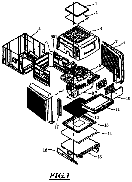
Rotisserie air-fryer oven
An air-fryer oven with a motorized rotating cage inside, so food tumbles in the hot air for even cooking.
US 11,187,373 B2 · Title as filed: Television mounting brackets · Inventors: Levy; Shlomo
Sheet 1 of 15 from the published document. All sheets in the USPTO PDF
A wall bracket in two parts, one on the wall and one on the TV, that hook together to hang it.
A television mounting bracket for hanging a television on a wall that include a first body that is designed to be connected to the wall and a second body that is designed to be connected to the television. The first body has a vertical c-profile channel that has a top opening and a vertical slot. The bottom part of the c-profile channel is narrower than the rest of it. The first body has a horizontal springy pin that is connected to its back part with a spring and protrudes from it into the c-profile channel in a way that enable the springy pin to move backward and forward. The second body has a horizontal pin with a locking piece that includes a vertical channel. The locking piece corresponds with the vertical slot and the vertical channel corresponds with the horizontal springy pin.
There are many types of TV brackets that include two parts: one part to be connected to the TV and the other one to be connected to the wall, then combine the two parts by sliding one part into the other. In many cases, members of the house or guests rise up and accidentally push the TV upwards that comes out of the brackets and falls to the floor or on the household members. The present invention provides an effective solution to this problem.
The first 3 of 15 drawing sheets from the published document, cropped to the drawing. Every sheet is in the USPTO PDF.
Independent claims and the claims that build on them, read from each claim's text.
What the patent claimed, word for word. All of it is now free to use.
The present invention refers to television mounting brackets ( 100 ) for hanging a television on a wall.
There are many types of TV brackets that include two parts: one part to be connected to the TV and the other one to be connected to the wall, then combine the two parts by sliding one part into the other. In many cases, members of the house or guests rise up and accidentally push the TV upwards that comes out of the brackets and falls to the floor or on the household members. The present invention provides an effective solution to this problem.
The intention of the drawing attached to the application is not to limit the scope of the invention and its application. The drawing is intended only to illustrate the invention and it constitutes only one of its many possible implementations.
FIG. 1 depicts the first body ( 10 ) and its elements.
FIG. 2 depicts the first body ( 10 ) and the second body and their elements.
FIG. 3 depicts a cross section view of the first body ( 10 ) and the second body.
FIG. 4 depicts a cross section view of the first body ( 10 ) and the second body ( 20 ) after being connected.
FIG. 5 depicts the television mounting bracket ( 100 ).
FIGS. 6-10 show the second body ( 20 ) and the first body ( 10 ) in several states.
FIGS. 11-13 depict schematically dimensions and proportions of elements of the television mounting bracket ( 100 ).
FIGS. 14-19 depict cross section views of several positions of the first body ( 10 ) together with the second body ( 20 ).
The main objective of the present invention is to provide a television mounting bracket ( 100 ) for hanging a television on a wall. The television mounting bracket ( 100 ) includes a first body ( 10 ) that is designed to be connected to the wall and a second body ( 20 ) that is designed to be connected to the television.
The first body ( 10 ) has a vertical channel in the profile of the letter C ( 11 ) (hereinafter and in the claims “a vertical c-profile channel”) that has a top opening ( 12 ) and a vertical slot ( 13 ). The bottom part ( 14 ) of the vertical c-profile channel is narrower than the rest of the vertical c-profile channel ( 15 ). The first body ( 10 ) has also a horizontal springy pin ( 16 ) that protrudes from the back part ( 17 ) of the first body itself into the vertical c-profile channel. The springy pin ( 16 ) is connected to the back part of the first body with a spring ( 161 ) in a way that it is possible to repel the springy pin backward and it returns to its place by the force of the spring. The first body ( 10 ) may also include holes and screws for connecting it to the wall.
The second body ( 20 ) has a horizontal pin ( 21 ) that is ended with a locking piece ( 22 ) that includes a vertical channel ( 23 ). The locking piece ( 22 ) corresponds with the vertical slot ( 13 ) and the vertical channel ( 23 ) corresponds with the horizontal springy pin ( 16 ). The second body ( 20 ) may also include holes and screws for connecting it to the television.
FIG. 1 depicts the first body ( 10 ) and its elements. FIG. 2 depicts the first body ( 10 ) and the second body ( 20 ) and their elements. FIG. 3 depicts cross section view of the first body ( 10 ) and the second body before connecting them together. FIG. 4 depicts cross section view of the first body ( 10 ) and the second body ( 20 ) after being connected. FIG. 5 depicts the television mounting bracket ( 100 ) when the first body and the second body are connected.
In this paragraph we will explain how to install and use the television mounting bracket ( 100 ) and how it works and by that to provide better understanding as to the structure of its parts and elements. It is preferable to use two television mounting brackets ( 100 ) to hang a television on the wall.
First: connecting the first body ( 10 ) to the wall in a way that the vertical slot ( 13 ) is facing outside and connecting the second body ( 20 ) to the back of the television in a way that the horizontal pin ( 21 ) with the locking piece ( 22 ) are facing outside. Second: connecting the second body ( 20 ) (with the television that is connected to it) to the first body ( 10 ) which is already connected to the wall, simply by inserting the locking piece ( 22 ) through the top opening ( 12 ) into the vertical c-profile channel ( 11 ) and accordingly the horizontal pin ( 21 ) slides down along the vertical slot ( 13 ).
FIG. 6 shows the step of bringing the second body ( 10 ) nearby the first body ( 10 ) before connecting them together. When the locking piece ( 22 ) slides down along the vertical c-profile channel ( 11 ), as depicted for example in FIGS. 7 and 8 , it repels back the horizontal springy pin ( 16 ). Immediately after that, when the locking piece ( 22 ) reaches the bottom part ( 14 ) of the vertical c-profile channel ( 11 ), two things happen: (a) the horizontal springy pin ( 16 ) returns to its place and is now in the upper part ( 231 ) of the vertical channel ( 23 ) as depicted in FIG. 9 ; and (b) the locking piece ( 22 ) is now positioned in the narrow bottom part ( 14 ) of the vertical c-profile channel ( 11 ) so that it is impossible to move is horizontally (Forward or backward) (hereinafter and in the claims “locked position”).
When the television mounting bracket ( 100 ) is in the locked position, as depicted in FIG. 9 and explained above, and the user in mistake pushes the television upward, the horizontal springy pin ( 16 ) that is inserted in the vertical channel ( 23 ) reach now to the bottom part ( 232 ) of the vertical channel ( 23 ), as depicted in FIG. 10 , and prevents the second body ( 10 ) from exiting the vertical c-profile channel ( 11 ). We use a language whereby the springy pin ( 16 ) reach up or down along the vertical channel ( 23 ) for convenience reasons only, although in fact is that the vertical channel ( 23 ) goes up and down with the locking piece ( 22 ) while the springy pin ( 16 ) together with the second body ( 20 ) and wall are left in place, thank God.
When the user wants to pull out the second body 20 from the first body 10 (to remove the television from the wall) he or she should simply lift the second body 20 slightly to the position where the springy pin 16 is positioned at the bottom part 232 of the vertical channel 23 ( FIG. 10 ) and in this state the locking piece 22 is no longer in the narrow bottom part 14 of the vertical c-profile channel 11 but in its wider part ( 15 W). Then the user can simply pull back the second body 20 to the state where the springy pin 16 is no longer inside the vertical channel 23 of the locking piece 22 , and then the second body 20 can be removed from the first body 10 , means to remove the TV from the wall.
It is understood from the above explanations and from the attached drawings, that it is important that the dimensions and proportions of the narrow bottom part 14 , the springy pin 16 , the locking piece 22 and the vertical channel 23 be matched and compatible. FIGS. 11-13 depict schematically these dimensions and proportions as follows: (a) The width ( 22 w ) of the locking piece ( 22 ) should match the width ( 14 w ) of the narrow bottom part ( 14 ), so that the locking piece ( 22 ) cannot move forward or backward in this position, as depicted in FIG. 11 ; (b) Distance A (DA) is greater than Distance B (DB) plus Distance C (DC), means, DA>DB+DC, as described in FIG. 12 ; (c) Distance E (DE) is greater than Distance D (DD) plus Distance F (DF), means, DE>DD+DF, as described in FIG. 13 .
FIGS. 14-19 depict cross section views of several positions of the first body ( 10 ) together with the second body ( 20 ).
Fees are due 3.5, 7.5 and 11.5 years after grant. This patent expired on November 30, 2025, so the fee marked "not paid" was the one that went unpaid.
Television Mounting Brackets
Filed Feb 2020 · published Aug 2021Television mounting brackets
Filed Feb 2020 · granted Nov 2021Earlier publications, parents and continuations. None of them can still be enforced, or this patent would not be listed.
Prior art cited by the examiner or applicant. Useful when you check your own idea for novelty.
Names, summaries, modern angles and build ratings are Patent Yard's editorial notes. Everything else on this page comes from the documents linked above.