 Lapsed, fee not paid4 drawings
Robotics & Automation · US 8,677,854 B2
Modular robot arm joints
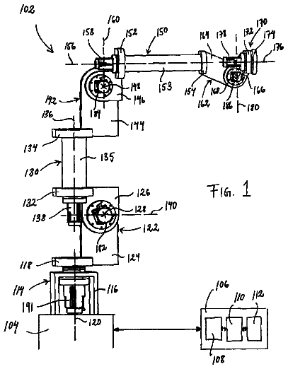
An industrial robot arm built from modules, each with two members that rotate about an axis.
US 11,112,780 B2 · Title as filed: Collaborative determination of a load footprint of a robotic vehicle · Assignee: Skylla Technologies, Inc. · Inventors: Weaver; Kota
Sheet 1 of 8 from the published document. All sheets in the USPTO PDF
One robot drives around another loaded robot and scans it to work out the true outline of the load it carries.
Methods and systems for collaboration between two robotic vehicle systems to accurately determine a geometric model of the footprint of a loaded robotic vehicle are described herein. A scanning robot is employed to scan a robotic vehicle loaded with a payload. The scanning robot measures the geometric information required to determine a geometric model of the loaded robotic vehicle. The scanning robot traverses a trajectory around the payload robot, while one or more distance sensors repeatedly measure the distance between the scanning robot and the payload robot and one or more image capture devices repeatedly image the payload robot. A geometric model of the footprint of the payload robot is generated based on the collected image and distance information. In some examples, virtual boundaries are defined around the payload robot based on the geometric model to navigate with obstacle avoidance.
Robotic systems are widely deployed to perform highly repetitive tasks, typically in a well-controlled, factory environment. In some examples of factory automation, a robot performs a single task repeatedly for long periods of time (e.g., months or years). However, the robotic systems are not yet widely deployed to perform tasks that are part of the everyday lives of humans. To better integrate robotic systems into the everyday lives of humans as well as custom workflows, robotic systems must be able to adapt to new tasks and environmental conditions. In some examples, robotic systems have been developed with increased intelligence to enable robotic systems to perform a wide range of tasks in unstructured environments. Intelligent robotic systems are able to better comprehend complex tasks and execute the task at hand with less instruction. In addition, improved user interfaces enhance c
The first 3 of 8 drawing sheets from the published document, cropped to the drawing. Every sheet is in the USPTO PDF.
Independent claims and the claims that build on them, read from each claim's text.
What the patent claimed, word for word. All of it is now free to use.
The described embodiments relate to systems and methods for payload transport in a service environment.
Robotic systems are widely deployed to perform highly repetitive tasks, typically in a well-controlled, factory environment. In some examples of factory automation, a robot performs a single task repeatedly for long periods of time (e.g., months or years). However, the robotic systems are not yet widely deployed to perform tasks that are part of the everyday lives of humans. To better integrate robotic systems into the everyday lives of humans as well as custom workflows, robotic systems must be able to adapt to new tasks and environmental conditions.
In some examples, robotic systems have been developed with increased intelligence to enable robotic systems to perform a wide range of tasks in unstructured environments. Intelligent robotic systems are able to better comprehend complex tasks and execute the task at hand with less instruction. In addition, improved user interfaces enhance communication between humans and a robotic system; enabling the collaborative robotic system to better understand the task at hand. Recent improvements to user interfaces include the use of natural user interfaces and the use of speech and gesture based technologies to improve usability of robots. However, these approaches focus on communicating task goals and constraints to the collaborative robotic system for execution solely by the robotic system. This limits the complexity of the task that can be accomplished by the robotic system due to limitations in the physical and intellectual capability of the robotic system and limitations in the ability to communicate task parameters and constraints to the robotic system.
A critical element of the navigation subsystem of a robotic vehicle is an internal model of the geometry of the robotic vehicle. This internal model enables the robotic vehicle to perform path planning and execute obstacle avoidance, as well as facilitate physical interactions with the surrounding environment. Models of the geometry of the robotic vehicle are often fixed models that are preprogrammed into the robotic system. However, this approach does not accommodate situations where the robotic vehicle payload changes over time. Cameras and other sensors on-board the robotic vehicle may be used to estimate the shape and size of a payload to determine the overall footprint of the robotic system. Unfortunately, it is often not feasible to include enough sensors with a sufficient field of view to accurately determine the size and shape of a payload when the payload is significantly larger than the robotic vehicle itself.
If a robotic vehicle has the opportunity to scan a payload before onboarding, the robotic vehicle may be able to estimate the size and shape of the payload with sufficient accuracy. However, if the payload is placed on the robotic vehicle, for example by a human or another mechanical system, in an unstructured manner, any available size and shape information cannot be easily relayed to the robot to accurately determine the footprint of the loaded robotic vehicle. To overcome this limitation, the robotic vehicle may be required to assume a very conservative navigation model, or rely on human input to identify a more accurate footprint estimate.
In summary, improvements to robotic systems are desired to enable high accuracy geometric modelling of a loaded robotic vehicle to enhance navigation in highly unstructured environments.
Methods and systems for collaboration between two robotic vehicle systems to accurately determine a geometric model of the footprint of a loaded robotic vehicle are described herein. A scanning robot is employed to scan a robotic vehicle loaded with a payload. The scanning robot measures the geometric information required to determine a geometric model of the loaded robotic vehicle.
The scanning robot traverses a trajectory around the payload robot, while one or more distance sensors repeatedly measure the distance between the scanning robot and the payload robot and one or more image capture devices repeatedly image the payload robot.
In one aspect, a computing system spatially locates the payload robot with respect to the scanning robot based on a collected sequence of images that include images of fiducial tags mounted to the payload robot.
In another aspect, the computing system detects a number of geometric feature points of payload robot from the collected sequence of images and distances. In some embodiments, the geometric feature points are corner points identified using standard, open source feature detector software such as the Shi-Tomasi corner detector, good features to track detector, Features from Accelerated Segment Test (FAST) detector, etc. In some embodiments, the feature detector is applied to all three color channels of each captured image along with the distance data.
In another aspect, the computing system computes position estimates of the detected feature points with respect to the coordinate frame fixed to the payload robot 100 using a homography. The estimates are refined by filtering the localization results through a Kalman filter associated with the known position and velocity of the scanning robot.
In some embodiments, the computing system filters the geometric feature points by distance and clusters the filtered geometric feature points. In some embodiments, a clustering algorithm such as agglomerative hierarchal clustering is employed. Any points located in the same cluster as the center point of the platform of the payload robot 100 are retained; the rest are discarded.
In some embodiments, a Kalman filter with a model for velocity and position is applied to each geometric feature point to reduce variance.
In another aspect, the computing system matches geometric feature points between each subsequent image frame. In some embodiments, a scale and rotation invariant feature descriptor such as Binary Robust Independent Elementary Features (BRIEF) is employed to perform the matching. In some embodiments, duplicate feature points are merged. In one example, feature points within two standard deviations of each other are merged.
After locating the set of geometric feature points, a mesh is created. In some embodiments, a mesh is generated by Poisson surface reconstruction. In some other embodiments, a simple bounding box mesh parameterized by the minimum and maximum values in each of the axes in the coordinate frame of the payload robot is generated.
After mesh generation, the mesh data is communicated to the payload robot. The payload robot updates the geometric model of its own footprint, including the payload. In some embodiments, the payload robot utilizes a two dimensional model of its footprint. In these embodiments, the three dimensional geometric model is flattened via orthographic projection from the top.
In a further aspect, virtual boundaries around the payload robot are defined based on a geometric model of the payload robot. In some examples, the virtual boundaries are employed to perform navigation tasks with obstacle avoidance.
The foregoing is a summary and thus contains, by necessity, simplifications, generalizations, and omissions of detail; consequently, those skilled in the art will appreciate that the summary is illustrative only and is not limiting in any way. Other aspects, inventive features, and advantages of the devices and/or processes described herein will become apparent in the non-limiting detailed description set forth herein.
FIG. 1 is a diagram illustrative of a scanning robot traversing a trajectory around a payload robot to build a geometric model of the payload robot including its payload.
FIG. 2 is a schematic diagram illustrative of elements of a system for collaboratively determining the load footprint of a payload robot.
FIG. 3 is a diagram illustrative of an embodiment of a payload robotic system 100 including a wheeled, robotic vehicle and payload platform in side view.
FIG. 4 is a diagram illustrative of an embodiment of a payload robotic system 100 including a wheeled, robotic vehicle and payload platform in top view.
FIG. 5 is a schematic diagram illustrative of some elements of a payload robotic system 100 .
FIGS. 6A-6D depict illustrations of a payload robotic system jointly executing a task with a human collaborator involving moving an object through a crowded environment.
FIG. 7 depicts an illustration of the interaction between a payload robotic system and an object in the surrounding environment.
FIG. 8 illustrates a flowchart of a method 600 for collaboratively determining a load footprint of a payload robot as described herein.
Reference will now be made in detail to background examples and some embodiments of the invention, examples of which are illustrated in the accompanying drawings.
Methods and systems for collaboration between two robotic vehicle systems to accurately determine a geometric model of the footprint of a loaded robotic vehicle are described herein. A second robotic vehicle is employed to scan the loaded robotic vehicle and provide the geometric information required to determine a geometric model of the loaded robotic vehicle.
FIG. 1 is a diagram illustrative of a scanning robot traversing a trajectory around a payload robot to build a geometric model of the payload robot including its payload. As depicted in FIG. 1 , scanning robot 300 traverses a trajectory 150 around payload robot 100 loaded with payload 110 . As depicted in FIG. 1 , scanning robot 300 includes a computing system 400 , one or more distance sensors 301 , and one or more imaging devices 302 . Coordinate frame {X.sub.SR, Y.sub.SR, and Z.sub.SR} is attached to scanning robot 300 . Payload robot 100 includes computing system 200 , payload platform 106 , payload 110 , and fiducial tags 115 A-D. Coordinate frame {X.sub.LR, Y.sub.LR, and Z.sub.LR} is attached to payload robot 100 .
As depicted in FIGS. 1-2 , scanning robot 300 includes one or more actuators 305 that cause the scanning robot to move along trajectory 150 around payload robot 100 in response to command signals 306 received from computing system 400 . One or more distance sensors 301 repeatedly measures the distance to the payload robot 100 as the scanning robot 300 traverses the commanded trajectory 150 .
Signals 303 indicative of the sequence of distances measured by the one or more distance sensors are communicated to computing system 400 . In addition, one or more image capture devices 302 repeatedly images the payload robot 100 as the scanning robot 300 traverses the commanded trajectory 150 . Signals 304 indicative of the sequence of images captured by the one or more image capture devices are communicated to computing system 400 . In some embodiments, the field of view of the one or more image capture devices includes the field of view of the one or more distance sensors. In some embodiments, an image capture device 302 is a three channel camera (e.g., RGB camera) that generates images with having three different color channels.
In some embodiments, computing system 400 spatially locates the payload robot 100 with respect to the scanning robot 300 based on the collected sequence of images. In the embodiment depicted in FIGS. 1-2 , the collected sequence of images includes images of fiducial tags 115 A-D within the field of view of the one or more imaging devices. The images of the fiducial tags are analyzed by computing system 400 to estimate the location of payload robot 100 with respect to the scanning robot 300 using one or more suitable localization algorithms. In some embodiments, the fiducial tags are AprilTags. Both AprilTags and associated localization software are freely available from the University of Michigan (USA) at the following Internet address: https://april.eecs.umich.edu/software/apriltaa.html.
Computing system 400 also detects a number of geometric feature points of payload robot 100 from the collected sequence of images and distances. In some embodiments, the geometric feature points are corner points identified using standard, open source feature detector software such as the Shi-Tomasi corner detector, good features to track detector, Features from Accelerated Segment Test (FAST) detector, etc. In some embodiments, the feature detector is applied to all three color channels of each captured image along with the distance data.
Computing system 400 also computes position estimates of the detected feature points with respect to the coordinate frame fixed to the payload robot 100 using a homography. The estimates are refined by filtering the localization results through a Kalman filter associated with the known position and velocity of scanning robot 300 . As scanning robot 300 traverses around the payload robot 100 , the positions of key feature points are recorded.
In some embodiments, computing system 400 filters the geometric feature points by distance and clusters the filtered geometric feature points. In some embodiments, a clustering algorithm such as agglomerative hierarchal clustering is employed. Any points located in the same cluster as the center point of the platform of the payload robot 100 are retained; the rest are discarded. Thus, there must be sufficient space between payload robot 100 and surrounding objects when scanning payload robot 100 by scanning robot 300 .
In some embodiments, a Kalman filter with a model for velocity and position is applied to each geometric feature point to reduce variance.
Computing system 400 also matches geometric feature points between each subsequent image frame. In some embodiments, a scale and rotation invariant feature descriptor such as Binary Robust Independent Elementary Features (BRIEF) is employed to perform the matching. In some embodiments, duplicate feature points are merged. In one example, feature points within two standard deviations of each other are merged. A scan of payload robot 100 is complete after scanning robot 300 has traversed a trajectory that completely encircles payload robot 100 .
After locating the set of geometric feature points, a mesh is created. In some embodiments, a mesh is generated by Poisson surface reconstruction. In some other embodiments, a simple bounding box mesh parameterized by the minimum and maximum values in each of the axes in the coordinate frame of payload robot 100 is generated. As payload robot 100 moves the entire system including both the payload and the robotic vehicle itself, feature points associated with the robotic vehicle are not filtered out.
After mesh generation, the mesh data (i.e., the geometric model of the payload robot 100 ) is communicated to the payload robot 100 . Payload robot 100 updates the geometric model of its own footprint, including the payload. In some embodiments, payload robot 100 utilizes a two dimensional model of its footprint. In these embodiments, the three dimensional geometric model is flattened via orthographic projection from the top.
FIG. 2 is a schematic diagram illustrative of elements of a system for collaboratively determining the load footprint of a payload robot. In some embodiments, payload robot 100 requests a scan of its footprint after an unknown load is placed on payload platform 106 . In some examples, payload robot 100 communicates a scan request over a peer-to-peer network. Scanning robot 300 receives this request and responds directly to scanning robot 300 . In some other examples, payload robot communicates a scan request to server 500 . In turn, server 500 broadcasts the scan request, identification number, and location of payload robot 100 . Server 500 conducts a search for any scanning robots that are nearby that are not currently undertaking any tasks. Server 500 selects a scanning robot (e.g., scanning robot 300 ) and notifies the scanning robot to conduct the scan.
As depicted in FIG. 2 , computing system 400 includes a sensor interface 410 , at least one processor 420 , a memory 430 , a bus 440 , a wireless communication transceiver 450 , and a controlled device interface 460 . Sensor interface 410 , processor 420 , memory 430 , wireless communication transceiver 450 , and controlled device interface 460 are configured to communicate over bus 440 .
Sensor interface 410 includes analog to digital conversion (ADC) electronics 411 . In addition, in some embodiments, sensor interface 410 includes a digital input/output interface 412 . In some other embodiments, sensor interface 410 includes a wireless communications transceiver (not shown) configured to communicate with a sensor to receive measurement data from the sensor.
As depicted in FIG. 2 , ADC 411 is configured to receive signals 303 from distance sensor 301 . ADC 411 is further configured to convert the analog signals 303 into equivalent digital signals suitable for digital storage and further digital processing. ADC 411 is selected to ensure that the resulting digital signal is a suitably accurate representation of the incoming analog signals (i.e., quantization and temporal discretization errors are within acceptable error levels). In some other embodiments, distance sensor 301 includes signal capture and processing capability on-board. In these embodiments, distance data are communicated digitally to computing system 400 .
As depicted in FIG. 2 , digital I/O 412 is configured to receive digital signals 304 from image capture device 302 . In this example, image capture device 302 includes on-board electronics to generate digital signals 304 indicative of captured images. In this manner, computing system 400 is configured to interface with both analog and digital sensors. In general, any of the sensors described herein may be digital or analog sensors, and may be communicatively coupled to computing system 400 by the appropriate interface.
Controlled device interface 460 includes appropriate digital to analog conversion (DAC) electronics. In addition, in some embodiments, controlled device interface 460 includes a digital input/output interface. In some other embodiments, controlled device interface 460 includes a wireless communications transceiver configured to communicate with a device, including the transmission of control signals.
As depicted in FIG. 2 , controlled device interface 460 is configured to transmit control commands 306 to one or more vehicle actuators 305 that cause the scanning robot 300 to move, for example, along a desired motion trajectory.
Memory 430 includes an amount of memory 431 that stores sensor data employed by scanning robot 300 to estimate a geometric model of payload robot 100 . Memory 430 also includes an amount of memory 432 that stores program code that, when executed by processor 420 , causes processor 420 to implement payload scanning task execution functionality as described herein.
In some examples, processor 420 is configured to store digital signals generated by sensor interface 410 onto memory 430 . In addition, processor 420 is configured to read the digital signals stored on memory 430 and transmit the digital signals to wireless communication transceiver 450 . In some embodiments, wireless communications transceiver 450 is configured to communicate the digital signals from computing system 400 to server 500 , computing system 200 , or an external computing device (not shown) over a wireless communications link. As depicted in FIG. 2 , wireless communications transceiver 450 transmits a radio frequency signal 452 over antenna 451 . The radio frequency signal 452 includes digital information indicative of the digital signals to be communicated from computing system 400 to the external computing device. In one example, sensor data generated by computer system 200 are communicated to server 500 , computing system 200 , or an external computing system (not shown) for purposes of scanning and generating a geometric model of payload robot 100 based on the sensor data.
In some embodiments, wireless communications transceiver 450 is configured to receive digital signals from server 500 , computing system 200 , or an external computing device (not shown) over a wireless communications link. The radio frequency signals 453 includes digital information indicative of the digital signals to be communicated from server 500 , computing system 200 , or an external computing system (not shown) to computing system 400 .
As depicted in FIG. 2 , server 500 includes at least one processor 520 , a memory 530 , a bus 540 , and a wireless communication transceiver 550 . Processor 520 , memory 530 , and wireless communication transceiver 550 are configured to communicate over bus 540 .
In some embodiments, memory 530 includes an amount of memory 531 that stores sensor data scanned by scanning robot 300 , mesh data associated with a geometric model of payload robot 100 , etc. Memory 530 also includes an amount of memory 532 that stores program code that, when executed by processor 520 , causes processor 520 to generate a geometric model of payload robot 100 based on sensor data collected by scanning robot 300 as described herein.
In some examples, processor 520 is configured to store digital signals received from computing systems 400 and 200 onto memory 530 . In addition, processor 520 is configured to read the digital signals stored on memory 530 and transmit the digital signals to wireless communication transceiver 550 . In some embodiments, wireless communications transceiver 550 is configured to communicate the digital signals from server 500 to computing system 400 , computing system 200 , or an external computing device (not shown) over a wireless communications link. As depicted in FIG. 2 , wireless communications transceiver 550 transmits a radio frequency signal 552 over antenna 551 . The radio frequency signal 552 includes digital information indicative of the digital signals to be communicated from server 500 to computing system 400 , computing system 200 , an external computing device, etc.
In some embodiments, wireless communications transceiver 550 is configured to receive digital signals from computing system 400 , computing system 200 , or an external computing device (not shown) over a wireless communications link. The radio frequency signals 553 includes digital information indicative of the digital signals to be communicated from computing system 400 , computing system 200 , or an external computing system (not shown) to server 500 .
In some embodiments, the scanning of payload robot 100 and geometric model building is performed by computing system 400 , and server 500 serves simply to communicate mesh data from computing system 400 to computing system 200 . Alternatively, computing systems 400 and 200 communicate directly and server 500 is not employed at all. However, in some embodiments, server 500 is employed to perform some or all of the calculation required to generate a geometric model of payload robot 100 from image and distance data generated by scanning robot 300 .
FIGS. 3 and 4 depict a side view and a top view of payload robotic system 100 , respectively, in one embodiment. Payload robotic system 100 includes a wheeled, robotic vehicle 101 with one or more actuated wheels (e.g., actuated wheels 102 A-D) attached to a frame 103 of the vehicle 101 . In some embodiments, wheeled, robotic vehicle 101 is an omni-directional robotic vehicle capable of translating in any direction in the xy plane and rotating about any axis parallel to the z-axis. In some of these embodiments, wheeled, robotic vehicle 101 is also holonomic, and thus is capable of independently translating in the xy plane and rotating about any axis parallel to the z-axis. In some embodiments, the one or more actuated wheels include a mecanum wheel, an omni-directional wheel, or any combination thereof. In one embodiment, wheeled, robotic vehicle 101 employs four mecanum wheels in direct drive. Computing system 200 communicates control commands to the actuated wheels of the wheeled, robotic vehicle that cause the wheeled, robotic vehicle to move in a desired direction in the xy plane and rotate about a desired axis parallel to the z-axis.
As depicted in FIGS. 3 and 4 , collaborative robotic system 100 also includes a payload platform 106 configured to carry a payload 110 . In some embodiments, payload robotic system 100 includes one or more payload platform actuators (not shown) attached to the frame and the payload platform. The payload platform actuators are configured to move the payload platform in a direction normal to the load carrying surface of the payload platform. In this manner, payload robotic system 100 is able to adjust a height of the payload platform 106 to meet the requirements of a variety of transportation tasks.
As depicted in FIG. 3 , payload robotic system 100 includes load sensors (e.g., load sensors 104 A-D). In the embodiment depicted in FIG. 3 , load sensors 104 A-D are coupled to payload platform 106 and frame 103 . In general, load sensors 104 A-D may be located in any suitable location in a load path between payload platform 106 and the actuated wheels (e.g., actuated wheels 102 A-D). The load sensors are employed to analyze the distribution of load on the payload platform.
In some embodiments, load sensors of collaborative robotic system 100 measure forces in a plane parallel to the loading surface of the payload platform. In the embodiment depicted in FIGS. 3 and 4 , load sensors 104 A-D measure forces in a plane parallel to the xy plane. Signals generated by load sensors 104 A-D are communicated to computing system 200 for further processing.
In some embodiments, a payload robotic system includes one or more proximity sensors configured to estimate the proximity of objects to the robotic system. In general, payload robotic system 100 includes proximity sensors of any suitable type. By way of non-limiting example, payload robotic system 100 may include proximity sensors such as capacitive sensors, Doppler effect sensors, Eddy-current sensors, inductive sensors, magnetic sensors, optical sensors, photoelectric sensors, photocell sensors, laser rangefinder sensors, passive sensors (e.g., charge-coupled devices), passive thermal infrared sensors, Radar sensors, sensors based on reflection of ionizing radiation, Sonar based sensors, ultrasonic sensors, fiber optic sensors, Hall effect sensors, or any combination thereof.
In some embodiments, proximity sensors include three dimensional sensors (e.g., three dimensional LIDAR sensors, stereoscopic cameras, time-of-flight cameras, monocular depth cameras, etc.) located along the perimeter of robotic system 100 (e.g., along the front, sides, back, of robotic system 100 , or any combination thereof). In some embodiments, RGB color information is employed in conjunction with depth data to estimate the proximity of objects relative to robotic system 100 .
Proximity sensors of payload robotic system 100 may be coupled to the wheeled, robotic vehicle 101 in any suitable manner. In some examples, the proximity sensors are coupled to frame 103 . In the embodiment depicted in FIGS. 3 and 4 , the proximity sensors 104 A-D are coupled to the payload platform 106 . Signals generated by proximity sensors 105 A-D are communicated to computing system 200 for further processing.
In some embodiments, payload robotic system 100 includes one or more image capture devices (e.g., charge coupled device (CCD) camera, complementary metal on silicon (CMOS) camera, etc.) also configured to estimate the proximity of objects to the robotic system. Signals generated by the image capture devices are communicated to computing system 200 for further processing.
FIG. 4 depicts a top view of the wheeled, robotic vehicle 101 and payload platform 106 of payload robotic system 100 . As depicted in FIG. 4 , wheeled robotic vehicle 101 includes actuated drive wheels 102 A-D. The relative angular velocity of each of the actuated drive wheels 102 A-D controls both the direction of the motion trajectory and the velocity along the motion trajectory of the wheeled, robotic vehicle 101 . Signals generated by computing system 200 are communicated to actuated drive wheels 102 A-D that causes the actuated drive wheels to move wheeled, robotic vehicle 101 along a desired motion trajectory at a desired velocity.
In some other embodiments, one or more wheels of wheeled robotic vehicle 101 are passive wheels that are free to rotate about multiple axes. In these embodiments, passive wheels function primarily to support the load normal to the ground surface, while the rotations of actuated drive wheels dictate the motion trajectory of the wheeled, robotic vehicle 101 . In some other embodiments, the orientation of one or more passive wheels about an axis normal to the ground surface is actively controlled. In these embodiments, these steering wheels also function to control the direction of the motion trajectory of the wheeled, robotic vehicle 101 . In some other embodiments, both the rotation of steering wheels and the orientation of steering wheels about an axis normal to the ground surface are actively controlled. In these embodiments, steering wheels function to control both the direction of the motion trajectory and the velocity along the motion trajectory of the wheeled, robotic vehicle 101 .
FIG. 5 is a diagram illustrative of elements of robotic system 100 including computing system 200 , platform load sensing devices 104 , wheel sensing devices 107 (e.g., encoders, wheel speed sensors, etc., located at each actuated wheel), proximity sensing devices 105 , image capture devices 108 , and wheel actuators 102 . In the embodiment depicted in FIG. 5 , computing system 200 is communicatively coupled to platform load sensing devices 104 , wheel sensing devices 107 (e.g., encoders located at each actuated wheel), proximity sensing devices 105 , image capture devices 108 , and wheel actuators 102 by wired communications links. However, in general, computing system 200 may be communicatively coupled to any of the sensors and devices described herein by either a wired or wireless communication link.
In general, any number of sensors and devices attached to collaborative robotic system 100 , including sensors and devices to interact audibly, visually, and physically with a human collaborator may also be communicatively coupled to computing system 200 .
As depicted in FIG. 5 , computing system 200 includes a sensor interface 210 , at least one processor 220 , a memory 230 , a bus 240 , a wireless communication transceiver 250 , and a controlled device interface 260 . Sensor interface 210 , processor 220 , memory 230 , wireless communication transceiver 250 , and controlled device interface 260 are configured to communicate over bus 240 .
Sensor interface 210 includes analog to digital conversion (ADC) electronics 211 . In addition, in some embodiments, sensor interface 210 includes a digital input/output interface 212 . In some other embodiments, sensor interface 210 includes a wireless communications transceiver (not shown) configured to communicate with a sensor to receive measurement data from the sensor.
As depicted in FIG. 5 , ADC 211 is configured to receive signals 202 from image capture devices 108 . In another non-limiting example, ADC 211 is configured to receive signals 203 from proximity sensing devices 105 . In another non-limiting example, ADC 211 is configured to receive signals 204 from platform load sensing devices 104 . ADC 211 is further configured to convert the analog signals 202 - 204 into equivalent digital signals suitable for digital storage and further digital processing. ADC 211 is selected to ensure that the resulting digital signal is a suitably accurate representation of the incoming analog signals (i.e., quantization and temporal discretization errors are within acceptable error levels). In some other embodiments, image capture devices 108 , proximity sensing devices 105 , and platform load sensing devices 104 include signal capture and processing capability on-board. In these embodiments, image data, proximity data, and load data are communicated digitally to computing system 200 .
As depicted in FIG. 5 , digital I/O 212 is configured to receive digital signals 201 from wheel sensing device 107 . In this example, wheel sensing devices 107 include on-board electronics to generate digital signals 201 indicative of a measured displacement, velocity, etc., of each actuated wheel of wheeled robot 101 . In this manner, computing system 200 is configured to interface with both analog and digital sensors. In general, any of the sensors described herein may be digital or analog sensors, and may be communicatively coupled to computing system 200 by the appropriate interface.
Controlled device interface 260 includes appropriate digital to analog conversion (DAC) electronics. In addition, in some embodiments, controlled device interface 260 includes a digital input/output interface. In some other embodiments, controlled device interface 260 includes a wireless communications transceiver configured to communicate with a device, including the transmission of control signals.
As depicted in FIG. 5 , controlled device interface 260 is configured to transmit control commands 205 to one or more wheel actuators 102 that cause the collaborative robotic system 100 to move, for example, along a desired motion trajectory. In another non-limiting example, controlled device interface 260 is configured to transmit command signals (not shown) to an audio output device, such as a speaker, that causes the speaker to audibly communicate with a human collaborator. In yet another non-limiting example, controlled device interface 260 is configured to transmit display signals (not shown) to an image display device that causes the image display device to visually communicate with the human collaborator. In general, any combination of audio/visual input and output devices may be contemplated to implement a natural language communication interface between collaborative robotic system 100 and a human collaborator to facilitate collaborative task execution as described herein.
Memory 230 includes an amount of memory 231 that stores sensor data employed by collaborative robotic system 100 to navigate an environment while collaboratively executing a task with a human collaborator. Memory 230 also includes an amount of memory 232 that stores program code that, when executed by processor 220 , causes processor 220 to implement payload transport task execution functionality including obstacle avoidance based on geometric models as described herein.
In some examples, processor 220 is configured to store digital signals generated by sensor interface 210 onto memory 230 . In addition, processor 220 is configured to read the digital signals stored on memory 230 and transmit the digital signals to wireless communication transceiver 250 . In some embodiments, wireless communications transceiver 250 is configured to communicate the digital signals from computing system 200 to an external computing device (not shown) over a wireless communications link. As depicted in FIG. 5 , wireless communications transceiver transmits a radio frequency signal 252 over antenna 251 . The radio frequency signal 252 includes digital information indicative of the digital signals to be communicated from computing system 200 to the external computing device. In one example, sensor data generated by computer system 200 are communicated to an external computing system (not shown) for purposes of monitoring and redirecting the robotic system 100 based on the sensor data.
In some embodiments, wireless communications transceiver 250 is configured to receive digital signals from an external computing device (not shown) over a wireless communications link. The radio frequency signals 253 includes digital information indicative of the digital signals to be communicated from an external computing system (not shown) to computing system 200 . In one example, a geometric mesh model of robotic system 100 loaded with a payload generated by an external computing system (e.g., computing system 400 or computing system 500 ) are communicated to computer system 200 for implementation by robotic system 100 . In some examples, an external computing system accesses additional sensor data (e.g., image data) that is otherwise unavailable to the collaborative robotic system 100 . This additional sensor data is employed by the external computing system to update a motion trajectory of collaborative robotic system 100 , for example, to avoid obstacles that are not within the field of view of collaborative robotic system 100 .
In one example, robotic system 100 operates with a human collaborator to carry a large object (e.g., a desk) through a crowded environment (e.g., an office). FIGS. 6A-6D depict illustrations of robotic system 100 jointly moving a desk 130 with a human collaborator 120 through a crowded environment including object 125 .
As depicted in FIG. 6A , robotic system 100 carries a portion of desk 130 on its payload platform and human collaborator 120 carries the remaining portion of desk 130 . In the scenario depicted in FIG. 6A , robotic system 100 and human collaborator 120 move desk 125 in the Y-direction (i.e., from right to left across the drawing page). Human collaborator 120 provides general navigation instructions by applying forces to desk 130 in a plane parallel to the XY plane. Robotic system 100 measures a force applied to the payload in a plane parallel to the XY plane by human collaborator 120 based on force signals received from load sensors 104 A-D. Computing system 200 determines a desired movement direction to be the direction of the measured force vector applied to the payload by the human collaborator in the plane parallel to the XY plane. For example, if the force applied to desk 130 in a plane parallel to the XY plane is aligned with the Y-direction, robotic system 100 determines the desired movement direction to be the Y-direction. However, if the force applied to desk 130 in a plane parallel to the XY plane is aligned with the X-direction, robotic system 100 determines the desired movement direction to be aligned with the X-direction.
For example, as depicted in FIG. 6A , human collaborator 120 applies lateral forces to desk 130 in a direction aligned with the Y-direction. At this instant, robotic system 100 responds by moving in the Y-direction. However, as depicted in FIG. 6B , human collaborator 120 applies forces to desk 130 in a direction that includes both X and Y components. At this instant, robotic system 100 responds by moving in a direction aligned with the forces applied to desk 130 by human collaborator 120 .
As depicted in FIGS. 6B and 6C , the forces applied to desk 130 (i.e., the navigational cues) by human collaborator 120 lead desk 130 on a collision course with object 125 .
In another aspect, robotic system 100 overrides the navigational cues of the human collaborator to avoid collisions between an object in the environment and any of the robotic system itself, the human collaborator, the shared payload, or any combination thereof.
The description continues in the full USPTO document.
Fees are due 3.5, 7.5 and 11.5 years after grant. This patent expired on September 7, 2025, so the fee marked "not paid" was the one that went unpaid.
Collaborative Determination Of A Load Footprint Of A Robotic Vehicle
Filed Mar 2019 · published Jun 2020Collaborative determination of a load footprint of a robotic vehicle
Filed Mar 2019 · granted Sep 2021Earlier publications, parents and continuations. None of them can still be enforced, or this patent would not be listed.
Prior art cited by the examiner or applicant. Useful when you check your own idea for novelty.
Names, summaries, modern angles and build ratings are Patent Yard's editorial notes. Everything else on this page comes from the documents linked above.