 Lapsed, fee not paid8 drawings
Vehicles & Drones · US 11,230,237 B1
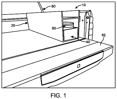
Truck bed tool drawer
A slide-out drawer toolbox with a built-in bucket that mounts in a vehicle.
US 11,110,849 B1 · Title as filed: Load securing device · Inventors: Alterie; Allen
Sheet 1 of 3 from the published document. All sheets in the USPTO PDF
A lever chain binder with a sealed bearing, shock cover and ergonomic handles for tying down loads.
A load securing device includes a lever binder used with chains or a similar fastener. The binder includes a sealed bearing, a shock cover, and ergonomic operational handles. The load securing device includes a first draw bolt and a second draw bolt that extends away from opposing sides of the bearing and are thus linearly arranged with respect to each other. The bearing is sealed to prevent rust or binding of the ratchet device with environmental debris.
There are countless tractor-trailer trucks that crisscross our country every day. These large vehicles bring just about every object we touch in our daily lives to use. One type of trailer commonly used with large or bulky objects such as PVC pipe, metal pipe, large tubing, logs, and the like is the flatbed trailer. Such a trailer does not only a great job of transporting such bulky loads but allows access to all three sides of the trailer for loading and unloading purposes. Such trailers and loads often use chains with a lever binder to hold such loads during transit. While lever binders have been used for generations, they are not without their faults. Their simple hinges can easily become bound up with rust making them difficult to open or close. Dirt and other contaminants can enter the mechanism not only making them hard to use, but perhaps even allowing them to open during use. Fin
All 3 drawing sheets from the published document, cropped to the drawing.
Independent claims and the claims that build on them, read from each claim's text.
What the patent claimed, word for word. All of it is now free to use.
The presently disclosed subject matter is directed to a load securing device.
There are countless tractor-trailer trucks that crisscross our country every day. These large vehicles bring just about every object we touch in our daily lives to use. One type of trailer commonly used with large or bulky objects such as PVC pipe, metal pipe, large tubing, logs, and the like is the flatbed trailer. Such a trailer does not only a great job of transporting such bulky loads but allows access to all three sides of the trailer for loading and unloading purposes. Such trailers and loads often use chains with a lever binder to hold such loads during transit.
While lever binders have been used for generations, they are not without their faults. Their simple hinges can easily become bound up with rust making them difficult to open or close. Dirt and other contaminants can enter the mechanism not only making them hard to use, but perhaps even allowing them to open during use. Finally, their metal handles can be painful to use should rust dings and scrapes cause sharp edges. Accordingly, there exists a need for a means by which lever binders can be used on flatbed trailers in a manner which addresses the disadvantages as described above. The development of the load securing device fulfills this need.
The principles of the present invention provide for a load securing device, comprising a handle and a ratchet device capable of incrementally operably retracting a first draw bolt and a second draw bolt towards each other. The ratchet device is also engaged by the handle. The load securing device also comprises an enclosed bearing housing the ratchet device and a first grease fitting located on the first draw bolt to provide enablement of introducing a first grease to the bearing to encourage friction-free movement, a second grease fitting located on the second draw bolt, respectively, to provide enablement of introducing a second grease to the bearing to encourage friction-free movement, a yoke which is attached to the housing of the bearing and is oriented perpendicular to the first draw bolt and second draw bolt, a handle pivot which affixes the plates together and is located at an opposing side of the yoke to the bearing, a first eye bolt which is attached to the second side of the first draw bolt opposite the bearing, an articulating first cover which is disposed between the first end of the bearing and the first eyebolt, a first buckle removably attaching a first hook to the first eyebolt, the first hook and the first eyebolt travels with the first draw bolt and a second buckle removably attaching a second hook to the second eyebolt. The second hook and the second eyebolt travels with the second draw bolt.
The handle may operably connected to a first end of the ratchet device and incrementally actuates the ratchet device so as to simultaneously retract the first draw bolt towards the bearing and to retract the second draw bolt towards the bearing. The handle may extend outward from in between the two plates of the yoke and is operably attached to the handle pivot. The first draw bolt may have a first end operably connected to a first end of the ratchet device within the bearing while the second draw bolt may have a first end operably connected to a second end of the ratchet device within the bearing.
The first draw bolt and the second draw bolt may extend away from opposing sides of the bearing and are thus linearly arranged with respect to each other. The first draw bolt may extend in and out of the first side of the bearing and may be actuated by the ratchet device.
The bearing may be sealed to prevent rust or binding of the ratchet device with environmental debris. The yoke may generally be two coextensive planar elements with a gap in the middle. The first draw bolt may be extended away from the bearing to a position that the first hook is secured into a link of a chain. The load securing device may be securely connected to the chain that securely wraps around the load secured at the first side or the second side of the bearing. The handle pivot may be operably attached to the ratchet device in between the two plates of the yoke adjacent the bearing. The handle may be motionable about the handle pivot to operate the ratchet device and may be available to be motioned towards either side, relative to the yoke, due to how the load securing device is installed.
The articulating first cover may be made of rubber. The articulating first cover may extend out of the first end of the bearing and prevent debris from entering the bearing. The load securing device may secure a load onto a towing vehicle. The towing vehicle may be a vehicle which is selected from the group consisting of a trailer that is not enclosed, a flatbed truck, or a gooseneck trailer. The load securing device may be manufactured out of a forged metallic material for strength and resiliency. The load securing device may be coated or treated with a protective material to resist rusting and damage from the environment. The protective coating may also provide for an enhanced grip when being manipulated.
The advantages and features of the present invention will become better understood with reference to the following more detailed description and claims taken in conjunction with the accompanying drawings, in which like elements are identified with like symbols, and in which:
FIG. 1 is a top perspective view of a load securing device 10 in a first configuration, according to the preferred embodiment of the present invention;
FIG. 2 is a top perspective view of the load securing device 10 in a second configuration, according to the preferred embodiment of the present invention; and,
FIG. 3 is an environmental view of the load securing device 10 in a second configuration, according to the preferred embodiment of the present invention.
10 load securing device 11 handle 12 yoke 14 a first grease fitting 14 b second grease fitting 16 bearing 17 handle pivot 20 a first side 20 b second side 21 a first draw bolt 21 b second draw bolt 22 a first cover 22 b second cover 23 a first eyebolt 23 b second eyebolt 24 a first buckle 24 b second buckle 25 a first hook 25 b second hook 30 locking lever 40 frame 41 tie-down location 42 vehicle 45 chain 50 load DESCRIPTION OF THE INVENTION
The best mode for carrying out the invention is presented in terms of its preferred embodiment, herein depicted within FIGS. 1 and 2 . However, the invention is not limited to the described embodiment, and a person skilled in the art will appreciate that many other embodiments of the invention are possible without deviating from the basic concept of the invention and that any such work around will also fall under scope of this invention. It is envisioned that other styles and configurations of the present invention can be easily incorporated into the teachings of the present invention, and only one
particular configuration shall be shown and described for purposes of clarity and disclosure and not by way of limitation of scope. All of the implementations described below are exemplary implementations provided to enable persons skilled in the art to make or use the embodiments of the disclosure and are not intended to limit the scope of the disclosure, which is defined by the claims.
The terms “a” and “an” herein do not denote a limitation of quantity, but rather denote the presence of at least one
of the referenced items.
Referring now to FIG. 3 , there is depicted an environmental view of a load securing device (herein described as the “device”) 10 in an exemplary method of use. The device 10 is particularly suited for securing a load 50 onto a towing vehicle 42 , such as a trailer that is not enclosed (e.g., a flatbed or gooseneck trailer), although other vehicles 42 where a load 50 needs to be properly secured can benefit from this invention. The device 10 is capable of secure connection to a chain 45 or similar device that securely wraps around the load 50 to be secured at a first side 20 a and is capable of secure connection to a tie-down location 41 (e.g., an eye hook or tow point) on a frame 40 of the towing vehicle 42 at a second side 20 b . Thus, the device 10 secures the chain 45 about a load 50 on the towing vehicle 42 . It is appreciated that either the first side 20 a or second side 20 b can engage either the chain 50 or the tie-down location 41 on the towing vehicle.
Referring now to FIGS. 1 and 2 , there is depicted a top perspective view of the device in a first configuration (i.e., a resting configuration, FIG. 1 ) and in a second configuration (i.e., a tensioning configuration, FIG. 2 ). More specifically, the device 10 has a handle 11 that engages a ratchet device (not shown) to incrementally operably retract a first draw bolt 21 a and a second draw bolt 21 b towards each other. The ratchet device is housed within an enclosed bearing 16 . The first draw bolt 21 a has a first end operably connected to a first end of the ratchet device within the bearing 16 and the second draw bolt 21 b has a first end operably connected to a second end of the ratchet device within the bearing 16 . The first draw bolt 21 a and second draw bolt 21 b extend away from opposing sides of the bearing 16 and are thus linearly arranged with respect to each other. A first grease fitting 14 a is located on the first draw bolt 21 a and a second grease fitting 14 b is located on the second draw bolt 21 b , respectively, to provide enablement of introducing a grease to the bearing 16 to encourage friction-free movement thereof.
The handle 11 is operably connected to a first end of the ratchet device and incrementally actuates the ratchet device so as to simultaneously retract the first draw bolt 21 a towards the bearing 16 and to retract the second draw bolt 21 b towards the bearing. A yoke 12 is attached to, or an integral part of, the housing of the bearing 16 and is oriented perpendicular to the first draw bolt 21 a and second draw bolt 21 b . The yoke 12 is generally two
coextensive planar elements with a gap in the middle. A handle pivot 17 affixes the plates together and is located at an opposing side of the yoke 12 to the bearing 16 . The handle 11 extends outward from in between the two
plates of the yoke 12 and is operably attached to the handle pivot 17 . The handle pivot 17 is operably attached to the ratchet device in between the two
plates of the yoke 12 adjacent the bearing 16 (not shown). The handle 11 is motionable about the handle pivot 17 to operate the ratchet device and is preferably available to be motioned towards either side, relative to the yoke 12 , due to how the device 10 is installed.
The first draw bolt 21 a extends in and out of the first side of the bearing 16 as actuated by the ratchet device. Attached to the second side of the first draw bolt 21 a , opposite the bearing 16 , is a first eyebolt 23 a . Disposed between the first end of the bearing 16 and the first eyebolt 21 a is an articulating first cover 22 a . The first cover 22 a can be rubber or some other material capable of covering the portion of the first draw bolt 21 a that extends out of the first end of the bearing 16 and prevent debris from entering the bearing 16 . A first buckle 24 a removably attaches a first hook 25 a to the first eyebolt 23 a . Thus, the first hook 25 a and first eyebolt 23 a travels with the first draw bolt 21 a.
The second draw bolt 21 b extends in and out of the second side of the bearing 16 as actuated by the ratchet device. Attached to the second side of the second draw bolt 21 b , opposite the bearing 16 , is a second eyebolt 23 b . Disposed between the second end of the bearing 16 and the second eyebolt 21 b is an articulating second cover 22 b . The second cover 22 b can be rubber or some other material capable of covering the portion of the second draw bolt 21 b that extends out of the second end of the bearing 16 and prevent debris from entering the bearing 16 . A second buckle 24 b removably attaches a second hook 25 b to the second eyebolt 23 b . Thus, the second hook 25 b and second eyebolt 23 b travels with the second draw bolt 21 b.
The device 10 is preferably manufactured out of a forged metallic material for strength and resiliency. All exposed metallic portions of the device 10 are preferably coated or treated with a protective material to resist rusting and damage from the environment. Such a protective coating can also provide for an enhanced grip when being manipulated. The first cover 22 a and second cover 22 b can be a resilient synthetic material. The bearing 16 is sealed to prevent rust or binding of the ratchet device with environmental debris such as dust, rocks, or ice.
In a preferred method of use, either the first side 20 a or second side 20 b is identified as being able to attach to the chain 45 or towing vehicle 42 . Once this determination is met, in an exemplary method of use, the first side 20 a is identified as attaching to the chain 45 . The first draw bolt 21 a is extended away from the bearing 16 to a position that the first hook 25 a is capable of securing into a link of the chain 45 . The second draw bolt 21 b is extended away from the bearing 16 to engage a secure connection to a tie-down location 41 of the towing vehicle 42 . Then, the handle 11 is motioned in a pivoting manner about the handle pivot 17 to engage the ratchet device. The ratchet device, in an incremental manner, retracts the first draw bolt 21 a and second draw bolt 21 b towards the bearing 16 . Each incremental movement engages the ratchet device to secure the desired position of the first draw bolt 21 a , and hence the chain 45 , towards the bearing 16 and simultaneously to secure the desired position of the second draw bolt 21 b , and hence the device 10 , towards the towing vehicle 42 . When the chain 45 is extremely taut against the load 50 , the handle 11 is left in the desired position, which secures the ratchet device from further movement. Other embodiments provide for a more positive lock for the ratchet device, such as a locking lever 30 on the bearing 16 that positively locks the handle 17 to set the desired position of the draw bolts 21 a , 21 b relative to the bearing 16 . The device 10 can be provided in different sizes and load ratings, according to the desired method of use.
The foregoing descriptions of specific embodiments of the present invention have been presented for purposes of illustration and description. They are not intended to be exhaustive or to limit the invention to the precise forms disclosed, and obviously many modifications and variations are possible in light of the above teaching. The embodiments were chosen and described in order to best explain the principles of the invention and its practical application, to thereby enable others skilled in the art to best utilize the invention and various embodiments with various modifications as are suited to the particular use contemplated.
Fees are due 3.5, 7.5 and 11.5 years after grant. This patent expired on September 7, 2025, so the fee marked "not paid" was the one that went unpaid.
Load securing device
Filed Mar 2020 · granted Sep 2021Earlier publications, parents and continuations. None of them can still be enforced, or this patent would not be listed.
Prior art cited by the examiner or applicant. Useful when you check your own idea for novelty.
Names, summaries, modern angles and build ratings are Patent Yard's editorial notes. Everything else on this page comes from the documents linked above.