 Lapsed, fee not paid8 drawings
Consumer Products · US 11,278,152 B2
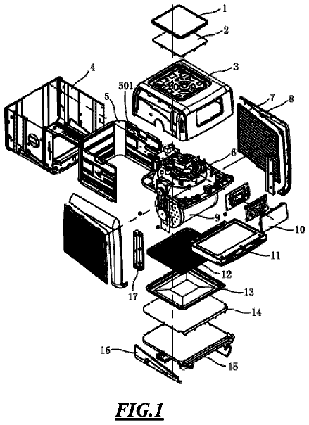
Rotisserie air-fryer oven
An air-fryer oven with a motorized rotating cage inside, so food tumbles in the hot air for even cooking.
US 11,110,737 B2 · Title as filed: Nib holder · Inventors: Umemura; Kazumasa
Sheet 1 of 7 from the published document. All sheets in the USPTO PDF
A case with a slider and pusher that swaps and holds pen nibs so you never touch the ink.
A nib holder. The nib holder includes a case having a nib insertion slot. A slider is contained within the case and has a plurality of connection pins and slider connection threads. A pusher is contained within the case and has a plurality of sliding slots. The pusher utilizes the sliding slots to establish a sliding connection to the slider via the slider's connection pins. A stopper is contained within the case. The stopper prevents horizontal motion of the pusher but permits vertical motion of the pusher. An adjuster has adjuster connection threads and utilizes the connection threads to mesh with the connection threads of the slider to establish a threaded connection. A nib is connected to the nib holder by insertion of the nib into the nib insertion slot and then rotation of the adjuster to raise the pusher vertically so that the nib is compressed between the pusher and the case.
Nibs and nib holders are known in the prior art. A nib is a pointed piece of metal that deposits ink onto a writing surface. A nib is mounted onto a nib holder to create a dip pen. Dipping pens are used by writers, artists and drafters for writing, calligraphy, sketching, mapping and technical drawing. FIG. 1 shows prior art nibs 1 and 2 . Nib 2 inserted into nib holder 3 to form dipping pen 5 . Nib 2 of dipping pen 5 may be dipped into ink jar 4 . Dipping pen 5 can then be used to write onto a paper writing surface. In the prior art nib 2 is press fit into nib holder 3 . Eventually, the attachment can weaken and the nib may become loose within the nib holder. This makes writing difficult and the dipping pen will eventually need to be discarded and replaced with a new functional nib holder. This can be frustrating, inconvenient, expensive and time consuming for the user. What is needed i
The first 3 of 7 drawing sheets from the published document, cropped to the drawing. Every sheet is in the USPTO PDF.
Independent claims and the claims that build on them, read from each claim's text.
What the patent claimed, word for word. All of it is now free to use.
This invention relates to dip pens, and in particular, to nib holders for dip pens.
Nibs and nib holders are known in the prior art. A nib is a pointed piece of metal that deposits ink onto a writing surface. A nib is mounted onto a nib holder to create a dip pen. Dipping pens are used by writers, artists and drafters for writing, calligraphy, sketching, mapping and technical drawing.
FIG. 1 shows prior art nibs 1 and 2 . Nib 2 inserted into nib holder 3 to form dipping pen 5 . Nib 2 of dipping pen 5 may be dipped into ink jar 4 . Dipping pen 5 can then be used to write onto a paper writing surface.
In the prior art nib 2 is press fit into nib holder 3 . Eventually, the attachment can weaken and the nib may become loose within the nib holder. This makes writing difficult and the dipping pen will eventually need to be discarded and replaced with a new functional nib holder. This can be frustrating, inconvenient, expensive and time consuming for the user.
What is needed is a better is a better nib holder.
The present invention provides a nib holder. The nib holder includes a case having a nib insertion slot. A slider is contained within the case and has a plurality of connection pins and slider connection threads. A pusher is contained within the case and has a plurality of sliding slots. The pusher utilizes the sliding slots to establish a sliding connection to the slider via the slider's connection pins. A stopper is contained within the case. The stopper prevents horizontal motion of the pusher but permits vertical motion of the pusher. An adjuster has adjuster connection threads and utilizes the connection threads to mesh with the connection threads of the slider to establish a threaded connection. A nib is connected to the nib holder by insertion of the nib into the nib insertion slot and then rotation of the adjuster to raise the pusher vertically so that the nib is compressed between the pusher and the case.
FIG. 1 shows a prior art nib, dipping pen and ink jar.
FIGS. 2-7 show components of a preferred embodiment of the present invention.
FIGS. 8-13 show a method for assembling a preferred embodiment of the present invention.
FIGS. 14-18 show a method for insertion of a nib into a preferred nib holder.
FIGS. 19-22 show a preferred nib insertion slot.
FIGS. 23-24 show another preferred embodiment of the present invention.
FIGS. 2-7 show components of a preferred embodiment of the present invention: case 10 ( FIG. 3 ), adjuster 11 ( FIG. 5 ), stopper 12 ( FIG. 6 ), pusher 13 ( FIG. 4 ), slider 14 ( FIG. 7 ), and guide 15 ( FIG. 2 ). In one preferred embodiment the components shown in FIGS. 2-7 are fabricated from metal. Assembly of a Preferred Nib Holder
In FIG. 8 , slider 14 and pusher 13 have been placed inside guide 15 . Sliding slots 81 ( FIG. 4 ) of pusher 13 have been aligned with pins 83 of slider 14 so that there is a sliding attachment between both parts.
In FIG. 9 , slider 14 , pusher 13 and guide 15 has been inserted into case 10 .
In FIG. 10 , stopper 12 has been inserted into gap opening 20 of case 10 .
In FIG. 11 , adjuster 11 is positioned next to case 10 and is ready for attachment.
In FIGS. 12-13 , threads 22 of adjuster 11 have been threaded onto threads 21 of slider 14 to form nib holder 50 . Installing a Nib into a Preferred Nib Holder
FIGS. 14 and 15 show slider 14 , stopper 12 and pusher 13 in the position shown in FIGS. 12-13 .
In FIG. 14 , a user has inserted Nib 55 into nib insertion slot 57 in case 10 , see also FIG. 3 .
In FIG. 16 , the user has rotated adjuster 11 further clockwise thereby causing slider 14 to move rightward. The horizontal rightward motion of pusher 13 is blocked by stopper 12 . The rightward motion of slider 14 has caused pins 83 of slider 14 also to move rightward, as shown. Pusher 13 cannot move rightward because its horizontal motion is blocked by stopper 12 . However, because pusher 13 is slidingly attached to slider 14 via pins 83 , pusher 13 moves vertically upward as shown (see also FIG. 17 ). Nib 55 is compressed between pusher 13 and case 10 , firmly securing nib 55 in place as shown.
In FIG. 18 , nib 55 is firmly held secure within case 10 to form dip pen 110 . Dip pen 110 is ready for usage as shown.
FIGS. 19-22 show a front view of case 10 . In a preferred embodiment, nib insertion slot 57 includes primary arc 71 and smaller secondary arc 72 .
FIG. 19 shows the insertion of thin nib 55 A. In FIG. 20 , the user has rotated adjuster 11 clockwise causing pusher 13 to rise vertically and compress thin nib 55 A between pusher 13 and case 10 . The utilization of secondary arc 72 creates three points of contact ( 96 - 98 ) for increased stability.
FIG. 21 shows the insertion of thick nib 55 B. In FIG. 22 , the user has rotated adjuster 11 clockwise causing pusher 13 to rise vertically and compress thick nib 55 A between pusher 13 and case 10 . The utilization of secondary arc 72 creates three points of contact ( 96 - 98 ) for increased stability. Other Preferred Embodiment
FIGS. 23 and 24 show another preferred embodiment of the present invention.
In FIG. 23 , threads 22 a of adjuster 11 a have been threaded onto threads 21 a of slider 14 a to form nib holder 50 a . End cap 99 a has been attached as shown.
In FIG. 23 , a user has inserted nib 55 into nib insertion slot 57 a in case 10 a.
In FIG. 24 , the user has rotated adjuster 11 a further clockwise thereby causing slider 14 a to move rightward. The rightward horizontal motion of pusher 13 a is blocked by stopper 12 a . The rightward motion of slider 14 a has caused pins 83 a of slider 14 a also to move rightward, as shown. Pusher 13 a cannot move rightward because its horizontal motion is blocked by stopper 12 a . However, because pusher 13 a is slidingly attached to slider 14 a via pins 83 a , pusher 13 a moves vertically upward as shown. Nib 55 is compressed between pusher 13 a and case 10 a , firmly securing nib 55 in place as shown.
Although the above-preferred embodiments have been described with specificity, persons skilled in this art will recognize that many changes to the specific embodiments disclosed above could be made without departing from the spirit of the invention. Therefore, the attached claims and their legal equivalents should determine the scope of the invention.
Fees are due 3.5, 7.5 and 11.5 years after grant. This patent expired on September 7, 2025, so the fee marked "not paid" was the one that went unpaid.
NIB HOLDER
Filed Nov 2019 · published May 2021Nib holder
Filed Nov 2019 · granted Sep 2021Earlier publications, parents and continuations. None of them can still be enforced, or this patent would not be listed.
Prior art cited by the examiner or applicant. Useful when you check your own idea for novelty.
Names, summaries, modern angles and build ratings are Patent Yard's editorial notes. Everything else on this page comes from the documents linked above.