 Lapsed, fee not paid4 drawings
Industrial Equipment · US 11,282,406 B2
Dropped-object reaction trainer
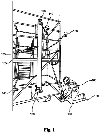
A tube rig that drops an object from above to show workers how little time they have to react to falling tools.
US 11,088,502 B1 · Title as filed: Wire termination assembly station and universal applicator for insulation displacement (IDT) strip terminals and connectors therefor · Inventors: Tillotson, Jr.; John D
Sheet 1 of 13 from the published document. All sheets in the USPTO PDF
A work cell with a spring or air-powered press that terminates a whole row of wires into connectors in one stroke.
A wire harness assembly work cell includes a wire harness assembly work table with a pneumatically powered or spring-fed universal applicator tool for mass terminating sets of wires into insulator wafers. The insulator wafers may be assembled in stacks to form cable-end connector headshells. Insulation displacement terminals (IDT) are designed to receive wide ranges of wire diameters so that larger varieties of wire sizes may be received into these connector assemblies while using fewer different sizes of terminals, thus reducing the number of items in a bill of material (BOM) and substantially reducing the volumes and overhead costs of testing and quality control documentation dedicated to each individual BOM item.
Manufacturers of discrete wire harness assemblies must usually arrange to provide an extensive inventory of components that require high labor content to assemble in order to produce acceptable finished products to their OEM customers. Labor-intensive tasks commonly include selecting and handling correct wires types and sizes, and selecting from a myriad of loose piece components such as connector housings, hardware, clips, terminals, all of from among large numbers of bulk supplies. Other tasks include pulling wire and routing groups of wires around pegs and other such layout fixtures to establish proper lengths for each wire of a product being manufactured, inserting wires into terminal and jacket crimping and forming machines, and snapping or inserting terminated wires into proper cavities of cable end connector housings, or arranging groups of wires cables onto insulation-displacemen
The first 3 of 13 drawing sheets from the published document, cropped to the drawing. Every sheet is in the USPTO PDF.
Independent claims and the claims that build on them, read from each claim's text.
What the patent claimed, word for word. All of it is now free to use.
A portion of the disclosure of this patent document contains material that is subject to copyright protection. The copyright owner has no objection to the facsimile reproduction by anyone of the patent document or the patent disclosure as it appears in the Patent and Trademark Office patent file or records, but otherwise reserves all copyright rights whatsoever.
The invention generally relates connector assembly fixturing and machinery and mechanical devices and aids for increasing assembly productivity of electrical connectors and wire harnesses which have electrical connectors at their various ends.
Manufacturers of discrete wire harness assemblies must usually arrange to provide an extensive inventory of components that require high labor content to assemble in order to produce acceptable finished products to their OEM customers. Labor-intensive tasks commonly include selecting and handling correct wires types and sizes, and selecting from a myriad of loose piece components such as connector housings, hardware, clips, terminals, all of from among large numbers of bulk supplies. Other tasks include pulling wire and routing groups of wires around pegs and other such layout fixtures to establish proper lengths for each wire of a product being manufactured, inserting wires into terminal and jacket crimping and forming machines, and snapping or inserting terminated wires into proper cavities of cable end connector housings, or arranging groups of wires cables onto insulation-displacement devices and mass-terminating these groups using an arbor press or some other high-force machine.
Thus cable assembly work entails much dexterity, attention to details, fine finger work, the ability to follow complex assembly and testing instructions, and to react correctly as these instructions are changed to follow various and flexible production schedules. Wire harness manufacturing entails an intense amount of complex and detailed work, all of which must be executed competently and correctly.
Thus opportunities exist and will continue to exist for reducing labor costs by simplifying tasks, providing machines that can execute sets of similar functions simultaneously, and machinery of fixtures which are easy to re-configure so that flexible manufacturing work cells may convert from one setup to the next with less time, less effort, and while minimizing the opportunity for manufacturing errors.
From the aforementioned background it is understood that many objectives exist. A primary objective of the invention is to arrange and provide a configurable fixture for use within a work station to assist with pulling wires, cutting them to required lengths, and preparing wire ends such as by stripping off insulation jackets or by crimping terminals to wire ends.
Since the largest portion of the expense in producing a wire harness assembly is in the management of so many different wires and leads, another objective of the invention is to reduce a unit cost of the harness produced in the work station by enabling mass terminations or in-gang assemblies of similar or sufficiently identical components so that a single action of an application-specific machine or tool may correctly and completely execute a plurality of similar or identical assembly steps in several closely collected locations. Thus another objective of the invention is to enable pulling and cutting to length of appropriate wires in sets of two or more wires at a time.
Another objective of the invention is to provide assembly fixtures and aids which simplify or eliminate steps in the processes of applying terminals to prepared wire ends, inserting terminated wire ends into insulator housings, and combining connector subassemblies to form completed connectors at appropriate wire harness locations.
Yet another objective of the invention is to provide for electrical testing and verification of terminals while they are affixed to wire ends but before they have been fully and permanently inserted into their insulator housings.
Combined with a capability to perform more than one identical task in a single space, it is therefore an additional objective of the invention to arrange all assembly and process infrastructures in a smaller space and volume than current methodologies typically require and consume.
From the foregoing, there is also seen a need for streamlining the process for changing over a set-up for making one assembly to a configuration for making a different assembly. Universal, programmable tooling may then effect substantial cost savings over current manufacturing operations. Various devices are currently available which attempt to address these challenges, although they may at best meet only one or two aspects of the totality of the requirements.
A further understanding of the nature and advantages of particular embodiments may be realized by reference to the remaining portions of the specification and the drawings. Similar reference numerals are used to refer to similar components.
FIG. 1 a shows a cable assembly work center which includes assembly machinery in accordance with the invention.
FIG. 1 b shows a back wall, a movable ram, and other components in accordance with the invention.
FIG. 1 c shows a fine-pitch helical spring used to retain wires at various pitches between its coils.
FIG. 2 a shows a front elevation view of a back wall and a portion of a work station including a universal applicator tool driven by a movable automated vertical ram.
FIG. 2 b shows an oblique, rear left top view of the of back wall, universal applicator tool and movable automated vertical ram of FIG. 2 a.
FIG. 3 a shows an oblique, front left top view of the universal applicator tool and movable automated vertical ram of FIG. 2 a and also a slidable magazine in accordance with the invention.
FIG. 3 b shows an oblique, front left top view of the universal applicator tool abutted to a workbench surface with the wire retaining helical spring nearby to assist laying out of wires to be assembled into connector wafers and headshells.
FIG. 4 a shows a left rear view of an applicator tool atop a connector assembly magazine in accordance with the invention.
FIG. 4 b shows a rear view of the spring feed applicator of FIG. 4 a and the advancing motion of the magazine.
FIG. 4 c shows an alternative assembly operating mode of the applicator tool in which the magazine is fixed, and the applicator is coupled for to the workbench for lateral motion along the length of the magazine.
FIGS. 5 a , 5 b , and 5 c show the timing of an applicator configured to perform a first IDT insertion operation and a second jacket crimp operation separately.
FIG. 6 a shows a cable end connector assembly having terminals, an insulator housing, and a terminal keeper bar.
FIG. 6 b shows an alternative embodiment of a connector assembly or subassembly in accordance with the invention.
FIG. 6 c shows another alternative embodiment of a subassembly in accordance with the invention.
FIG. 6 d shows an embodiment of a multiple-row connector assembly with its wafers exploded apart.
FIG. 6 e shows the multiple-row connector assembly of 6 d with its wafers snapped together.
FIG. 7 a shows a magazine with some of its bays populated with connector insulator housings ready for assembly, and finished connectors in other bays, and one connector and its terminals and wires in an intermediate assembly stage.
FIG. 7 b shows the connector of FIG. 7 a in its intermediate assembly stage with other components omitted for clarity.
FIG. 7 c shows an electrical testing substructure in accordance with another alternate embodiment of the invention.
FIG. 8 a shows a connector assembly fixture in accordance with the invention.
FIG. 8 b shows a cable end connector assembly step wherein terminals may be electrically tested before being inserted into a connector insulator housing.
FIG. 8 c shows another view of a cable end connector assembly step after the crimp wings formed over into a permanent, assembled condition.
FIG. 9 a shows an IDT insertion tool for terminating wires to contacts in accordance with the invention.
FIG. 9 b shows a set of forming tools for closing crimp wings onto wire jackets of an array of wires held within an application specific assembly fixture, in which the upper-side forming tools are adjustable by height.
FIG. 9 c shows a set of forming tools for closing crimp wings onto wire jackets of an array of wires held within an application specific assembly fixture, in which the anvils are adjustable by height.
While various aspects and features of certain embodiments have been summarized above, the following detailed description illustrates a few exemplary embodiments in further detail to enable one skilled in the art to practice such embodiments. The described examples are provided for illustrative purposes and are not intended to limit the scope of the invention.
In the following description, for the purposes of explanation, numerous specific details are set forth in order to provide a thorough understanding of the described embodiments. It will be apparent to one skilled in the art, however, that other embodiments of the present invention may be practiced without some of these specific details. Several embodiments are described herein, and while various features are ascribed to different embodiments, it should be appreciated that the features described with respect to one embodiment may be incorporated with other embodiments as well. By the same token, however, no single feature or features of any described embodiment should be considered essential to every embodiment of the invention, as other embodiments of the invention may omit such features.
In this specification, the term “means for . . . ” as used herein including the claims, is to be interpreted according to 35 USC 112 paragraph 6. In method claims, a step said to be performed “after” a prior step may be performed immediately after the prior step, or it may be performed after other intervening steps are also performed after the prior step.
Unless otherwise indicated, all numbers herein used to express quantities, dimensions, and so forth, should be understood as being modified in all instances by the term “about.” In this application, the use of the singular includes the plural unless specifically stated otherwise, and use of the terms “and” and “or” means “and/or” unless otherwise indicated. Moreover, the use of the term “including,” as well as other forms, such as “includes” and “included,” should be considered non-exclusive. Also, terms such as “element” or “component” encompass both elements and components comprising one unit and elements and components that comprise more than one unit, unless specifically stated otherwise. The word “by” in this specification not only means “by means of” in some instances in this specification and claims, but in other instances “by” is a preposition also meaning “at,” “in the vicinity of,” or “next to.”
In this specification the word “substantially” when used as a comparative, such as a first quantity, parameter, or geometric entity being “substantially equal to” or “substantially parallel to” or “substantially perpendicular to” a second quantity, parameter, or geometric entity shall be taken to mean that for numerical values the second value resides within 10% of the first value and for angular measures the second entity resides within 10° of the condition referencing the first entity.
Also in this specification the word “wire” may be used interchangeably with the word “cable” when meaning a single strand structure comprising a solid or a stranded central conductor surrounded by an insulating coating or a jacket. A “wire” in this specification may have a solid central conductor or a braided or served strand built up from a plurality of solid conductors. Some wires have a built-up core of multiple conductors, with each individually coated with a solder or a brazing material which is heated to bond the group to act as a unitary conductor. Also in this specification, where the word “terminal” or its plural is used without any other adjacent word defining or limiting the scope or type of terminal, then the word applies to all types of terminals and all manners of bulk supplies of these terminals, such as side feed, end feed, and loose piece terminals. As the wires are drawn and cut to length by the invention material moves from bulk stores, through guiding devices such as fairleads and infeed guides, through clamps, outfeed guides, and wire cutters. The direction of material motion over time allows the use of relative words used to describe sequences in time such as “before” and “after” and words describing relative positions in a flow such as “ahead of,” “upstream,” and “downstream” to be used to describe the relative positions or sequences of components within a series of elements spaced out along a length of wire set up and threaded through the inventive machine.
During cable and wire harness assembly, fixtures are often used for assembling wire harnesses for nearly any industry, the devices and their arrangements as disclosed in this document may offer some of their greatest benefits and improvements to wire harness assembly in the automotive industry. Wire and lead production may proceed at a rate of more than 3,000 wires or leads per hour, and may include tasks such as handling wires of different gauges, different lengths, different colors, or having different terminals crimped to them, and other variations in accordance with customer requirements. A significant amount time is consumed in handling wires from the time they are produced to the time they are assembled on the harness boards and finally packaged and shipped. The time defined by movement of one cut wire length from one place to another is referred to as “in-process inventory movement” of wires or leads. Inventory retained for a long period of time has an inherent cost where return on investment is affected. By reducing in-process inventory time in the manufacturing cycle, the end cost of a completed wire assembly may also be effectively reduced, when compared to a conventional production arrangement as described in patent application Ser. No. 16/133,466 for its FIGS. 1 and 4a.
Now referring to the figures, FIG. 1 a shows a work center which includes assembly machinery in accordance with the invention, especially a wire termination assembly station and universal applicator in accordance with the invention. The work station shown includes termination tools or machines for terminals supplied in bulk such as side feed, end feed, and tape mounted terminals. The work cell is a configurable modular work space where assembly tools, jigs and fixtures, and machinery may be arranged for production and verification testing of various wire harness assemblies, wherein the modules and work spaces within the work cell may be rapidly, easily, and safely rearranged for most efficient production of a product to OEM or customer specifications.
Discrete wire termination stations have wire end applicator machines [ 107 ] which may be configured to process many types of wire terminals, including but not limited to end feed terminals, side feed terminals, loose terminals, and tape mounted terminals. Cost saving benefits include that the use of universal applicator tooling may eliminate a need to purchase or lease dedicated application tooling, and manufacturing time savings during setup or to transition from one terminal strip to another.
Although bulk quantities of wire are available in spools, tubs, boxes, or barrels, in this illustration wires are shown in spools [ 90 a ] arranged on a bulk supply frame [ 90 .] Bulk wire supplied by barrel may contain up to 17 miles of wire per barrel. Wires of various types and sizes are pulled from bulk supplies and routed to a programmable discrete wire inventory indexing system. The wires may be retained by insertion into gaps of an extended helical spring as is explained and illustrated below. Other bulk stores of wire may be located beneath the work center tables or may be located overhead or in an upper floor warehouse and routed from above as in [ 96 .]
Computers and video display monitors [ 98 ] are positioned at work areas and component storage areas and in view of workers at activity stations within the work cell. Display monitors may indicate inventory on hand and may be part of a kanban system for more automated inventory replenishment or a heijunka system for scheduling “pitches” of work intervals comprising mixed product production.
Predetermined lengths of loose wires are pulled, cut to length, and collected at the presentation table [ 95 .] Cost saving benefits include a capability for multiple wire types to be made available and ready at the assembly site, which reduces in-process inventory time, and time used for wire selection and lead preparation. An assembly workbench or work table [ 103 ] in accordance with the invention may include a form board [ 115 ] also called a finger board, which includes pegs for routing harness wiring between various cable end connector headshells. Linear arrays of various wire types [ 92 ] protrude through back walls [ 87 ] and side walls from local bulk stores [ 104 ] and spools at the perimeter of the work table, and operators may grab them singly or in groups or sets, which is an action called a “multiple wire pull.” Connector assembly and testing as described herein may also be performed within this work area providing further productivity improvements.
FIG. 1 b shows a back wall [ 87 ,] a movable ram [ 89 ,] and other components in accordance with the invention. The ram includes a helical ball screw system having a variable pitch helix with a first helical pitch in a first portion or first end of the helix which is larger (i.e, steeper) than a second helical pitch in a second portion or second end of the helix. A long, helical spring [ 85 ] having fine-pitch coils assist in laying out sets of wires to be terminated by electrical contacts for connector assembly work.
FIG. 1 c shows a fine-pitch helical spring [ 85 ] used to retain wires at various pitches between its coils. The spring [ 85 ] secured at both ends and extended so that the helix spreads to a substantially uniform pitch p 0 . As an assistance for placing wires of various sizes in position for mass termination, the extension of the spring can be set so that for wires of multiple pitches p 1 and p 2 , etc, the pitch of the helix is set to at or near the largest common denominator of the pitches to be terminated. For example, if signal wiring of a size [W 2 ] is spaced at 0.060 in apart (p 1 ) and power wiring of a size [W 4 ] is spaced at 0.090 in apart (p 2 ,) then the spring can be stretched so that the coil pitch and its openings between the coil reside on a pitch p 0 of 0.030 in apart.
A fence or a wire stop ahead or behind the extended helical spring may be used to set the longitudinal location of the wire end with respect to the spring. Wire-grabbing fixtures may be adjusted so the fence acts as a wire-end reference, so that such a grabbing fixture may accurately position a wire end in a terminating location, or may insert a wire end to a known depth inside an application specific tool such as a terminal applicator or a wire stripping machine.
FIG. 2 a shows a front elevation view of a back wall [ 87 ] and a portion of a work station including a universal applicator tool [ 250 ] driven by a movable automated vertical ram [ 89 .] In a preferred embodiment, the vertical ram includes a first motor driven power source used for horizontal movement and positioning along the back wall, and a second motor driven power source for raising and lowering its vertically oriented ram rod, which delivers terminal forming forces through to the forming tools affixed to the applicator tool and also delivers mechanical power to cock the applicator's spring-feed mechanism for advancing and separating strip fed terminal form a bulk supply such as terminals furnished on a pilot strip or furnished as mounted on mylar tape. For tape-mounted contacts the applicator tool functions much like a component pick and place machine for populating printed circuit board assemblies. The ram delivers forces and power to form terminals, assemble connectors, advance the connector magazine described further below, and to advance bulk supplies of terminals which may be furnished as side feed or end feed terminal, or tape mounted terminals.
The helical spring [ 85 ] for laying out connector leads is positioned along the work table or workbench perimeter and the ram may be translated along the transverse width of the back wall using a top rail and if required, an additional stabilizing or support rail residing within or part of a transverse slot [ 221 ] which extends for most of the width of the back wall.
FIG. 2 b shows an oblique, rear left top view of the of back wall [ 87 ,] universal applicator tool, and movable automated vertical ram [ 89 ] of FIG. 2 a . The ram translates along the width of the back wall slot [ 221 ] by means of a pinion or spur gear [ 225 ] which engages with a toothed rack [ 223 ] which resides in the slot. Although in a preferred embodiment the motion of the ram is automatically controlled by a production control computer, it is also possible to manually override or manually position this machine by means of a hand crank [ 226 ] affixed to the gear.
FIG. 3 a shows an oblique, front left top view of the universal applicator tool [ 250 ] and movable automated vertical ram [ 89 ] of FIG. 2 a and also a slidable magazine [ 240 ] in accordance with the invention. In this figure and some of the following figures, some common hardware such as fasteners and brackets are omitted so that the disclosure may concentrate on more salient and novel components. Nevertheless a tool maker of average skill in this specific art will easily appreciate how to fashion such objects so as to affix and orient the relevant components under discussion with respect to each other.
FIG. 3 b shows an oblique, front left top view of the universal applicator tool abutted to a workbench surface with the wire retaining helical spring [ 85 ] nearby to assist laying out of wires to be assembled into connector wafers and headshells. A spring-fed actuator indexes a connector wafer magazine [ 240 ] which includes a T-slot [ 245 ] which rides along a T-rail. The magazine includes a linearly spaced set of bays [ 243 ] for receiving insulator housings, and a portion having regularly-spaced sawtooth profiles [ 242 ] used to index the insulators as they are populated with sets of terminals as these are crimped to their wires by any of various forming and crimping tools [ 94 ] held by the applicator tool. These tools operate against an anvil tool [ 91 ] comprising a series of crimp forming sites which control shape and dimensions of the underside surface of the crimp wing portions of terminals while the wings are being formed. Another portion of the upper crimping tool forcibly inserts jacketed wires into the insulation displacement terminal (IDT) portion of the terminals which are inserted into the insulator headshells or wafers. Insulation displacement terminals are designed to lacerate wire jackets, expose the central conductive strands, and pinch the conductors securely to establish and maintain reliable electrical interconnections over the service life of the wire harness assembly. By bringing groups of wires to a wire stop in each multiple wire pull from appropriate bulk wire sources, and laying the wires atop the terminals, no wire cutting or trimming is necessary at the IDT terminals. The invention both eliminates individual, one at a time wire pulling and eliminates individual, one at a time wire termination tasks, while also enabling mass termination of groups of wires in a single tool hit with no wire cutting, stripping, tinning, or other wire end preparations being required.
The ram presses down onto a threaded shank [ 253 ] seated onto the upper of at least two forming tool height adjusting discs [ 252 a ] and [ 252 b .] According to one set of embodiments in accordance with the invention, the shank passes through and is threadably coupled to the first disc. The lower or lowest of these discs couples to a spring-loaded vertically movable column in the applicator tool by means of precision threads of a first pitch. The next disc above stacks atop the lower disc and couples to it by precision threads of a second pitch which is preferably a fractional pitch compared to the first pitch. The adjustment discs include a radial array of faces marked with indicia and are detented so that when rotated they click-stop at the indicated faces, allowing for very fine adjustment of the lowest stop point of the forming tool. For example, a first disc may have 10 faces around its circumference and be threaded on 2 mm pitch, and a second disc threadingly coupled to the first disc may have its own 10 faces but its thread pitch is 0.2 mm pitch. With both discs detented to click-stop at 36° rotational increments, the faces of the first disc would be marked “0.0,” “0.2” etc. to “1.8” and the second disc would be marked “0.00,” “0.02” etc. to “0.18.” Rotating the first disc from one click-stop to the next adjusts the stop height of the forming tool in 0.2 mm (0.0078 in) increments, with the finer pitch disc adjustable to 0.02 mm (0.0008 in) increments.
The applicator tool may thus be used to effect extremely precise control of forming and crimping operations, especially where overbending or over-compression of materials is required to assure proper and complete plastic deformation and fusion of gas-tight interconnections between conductors. Most metallic conductors accrue an oxide film while exposed to air, so plastic deformation is necessary to stretch and break open this oxide film to expose fresh metal which is immediately and permanently swaged to other freshly exposed metal in adjacent conductors. When performed correctly, permanent compressive forces left behind after such an operation exclude atmospheric corrosion from insinuating new oxide films between these metal to metal junctions, which is the definition of a gas-tight electrical interconnection.
FIG. 4 a shows a left rear view of an applicator tool atop a connector assembly magazine in accordance with the invention. The magazine includes a linearly spaced set of insulator-receiving bays [ 243 ] and a portion having regularly-spaced sawtooth profiles [ 242 ] used to index the insulators as they are populated with sets of terminals. A cam follower [ 255 ] rides along a guide which includes an arcuate profile [ 256 ] or “J” so that during the descent of the ram, the follower acquires an angular rotation which rotates a feed spindle to which it is coupled, and the rotation of the feed spindle drives a cocking rod which cocks the spring feed mechanism of the applicator. The cocking spring is housed in a tube which includes a threaded cap [ 261 ] for adjusting spring compression. A U-shaped spacer [ 244 ] sits upon the cocking rod with its arms preferably facing downward, and it is secured in place on the rod by a set screw collar [ 246 .] These two components are shown in duplicate exploded away from the assembly to show their features.
The cocking mechanism also cocks a spring which when released powers a drive dog [ 258 ] which has a pawl [ 259 ] which operates similar to a walking foot of a sewing machine; it is pinned to the lower end of the drive dog. Thus with successive ram operations from above, applicator advances sets of terminals supplied to it in bulk strips, in an in-feed direction shown by arrow [ 238 .] An illustration of a set of terminals [ 185 ] furnished on mylar tape is included in this figure. Preferred IDT terminals for use with this applicator and assembly system are designed to accept a wide range of wire sizes and configurations. A U-shaped spacer [ 244 ] sits upon the cocking rod with its arms preferably facing downward, and it is secured in place on the rod by a set screw collar [ 246 .] These two components control the throw length of the cocking mechanism so that the drive dog swings back far enough for the pawl to engage and drive the slidable magazine by passing over and catching the next peak of the sawtooth profile of the magazine. Wider insulator housings, such as those having more lines or larger terminals or both will require more generous swings of the drive dog to operate the pawl, and sets of U-spacers may be fashioned in various lengths so that a desired throw length for a given connector width is made available.
One of the most preferred terminal designs is disclosed by the inventor in application Ser. No. 16/516,672 which issued on 28 Jan. 2020 as U.S. Pat. No. 10,547,125. This type of terminal includes an opposed pair of pincers [ 30 ] with the wire being inserted in a direction perpendicular to the pincers. The terminals also include jacket crimp ears [ 77 .] The specific mating features of the contact are not within the scope of the invention, and may be rolled pins, blades, lugs, box-type contacts, duck-bill contacts, blade-on-beam designs, cantilever contacts or others known within the industry. In the figures, the particulars of the contact features are shown by a lozenge shaped volume [ 78 ] which represents any terminal contact configuration.
In the assembly system disclosed in this application, the terminals are lain horizontally and wires are lain atop each terminal. Then, the entire set of wires are forced into electrical interconnections in a single press from above. However, it is also within the scope of the invention to terminate wires to IDT terminals while these connector components are oriented differently, such as by a vertical rotating turret or carrousel system.
FIG. 4 b shows a rear view of the spring feed applicator of FIG. 4 a and the advancing motion of the magazine [ 240 .] The ram presses down onto a threaded shank [ 253 ] seated onto top of the spring feed applicator. A cam follower rides along a guide which includes an arcuate profile [ 256 ] or “J” to cock the spring during the descent of the ram. The spring [ 254 ] is housed in a tube which includes a threaded cap for adjusting spring compression. The magazine is indexed along a direction indicated by arrow [ 241 b ] as the cocking and releasing of the spring drives a drive dog [ 258 ] and pawl [ 259 ] in an oscillating arc shown by arrow [ 241 a .] Successive motions of the drive dog and pawl index the pawl over successive crests of the sawtooth profile, which advances the magazine by one connector bay per cycle. Also, in addition to a sawtooth profile [ 242 ,] a variant magazine having complementary rectangular wells [ 242 a ] punctuated by fences between the wells may also be driven by the pawl passing over a fence, dropping into a well, and then catching the root of the fence as a traction drive.
FIG. 4 c shows an alternative assembly operating mode of the applicator tool in which the magazine is fixed, and the applicator is coupled for to the workbench for lateral motion along the length of the magazine. Successive down-strokes of the ram (indicated by the arrow [ 257 a ,]) terminate and form the connectors in one bay while cocking the spring and the drive dog.
On the upstroke of the ram, the drive dog laterally translates the applicator (as indicated by the arrow [ 257 c ,]) and the ram is moved in tandem along the backwall by automatic control. The upstroke of the ram combined with its lateral motion chasing the applicator is shown by diagonal arrow [ 257 b .] Also, besides using a spring cocked by energy delivered by the ram, the applicator may also be powered by pneumatic or hydraulic means or by an electric solenoid. These alternate means may also advance the bulk supply of terminals supplied by strip, reel, or tape.
FIGS. 5 a , 5 b , and 5 c show the timing of an applicator configured as a wire terminating apparatus which performs a first IDT insertion operation and a second jacket crimp operation separately. Beginning with FIG. 5 a , the terminal (not shown) is lain upon two anvils, of which a first anvil [ 91 a ] is for the tool which forcibly inserts a wire lain atop the terminal into its IDT pincers. The mutually opposed pincers trap the wire from axial excursion over the life of the interconnection. However, with no other crimping or forming of the contact, at any time before the jacket crimp is made, the wire may be wrested from the pincer jaws and removed if such a rework operation is required. The first anvil is registered with the wire insertion tool and in contact with the second pressure surface so that force from the ram is directed to the insertion operation. Although the applicator may be used for many types of wire insertion tools, in this configuration the wire insertion tool is an insulation displacement terminal (IDT) insertion tool.
The jacket crimp wings of the terminal are lain atop a second anvil [ 91 b ] registered with the crimp forming tool. The threaded shank [ 253 ] of the applicator tool is height adjustable. The first threadably adjustable disc [ 252 a ] controls the height of the jacket crimp forming tool and its gap height above the terminal to be crimped. A first elastic member or set of springs [s 1 ] is or are disposed between the first adjustable disc and the second adjustable disc [ 252 b ] leaving a gap height [g 2 ] closable by overcoming the elastic compression forces in [s 1 .] Gap [g 2 ] is adjustable by rotating the first disc or the threaded shank, and gap [g 1 ] is adjustable by rotating the second disc. The first elastic member is compressible along an axial direction [A] and disposed between the first pressure surface and the second disc. The crimp forming tool is in contact with the first pressure surface.
The jacket crimp forming tool [ 94 b ] is connected to or impinged from above by an underside surface which is a first pressure surface of the first adjustable disc. The IDT insertion tool [ 94 a ] is connected to or impinged from above by an underside surface which is a second pressure surface of the second adjustable disc. The stack of discs rest upon a second elastic member or set of springs [s 2 ] disposed between the second adjustable disc and a stationary member of the applicator, leaving a gap height [g 1 ] closable by overcoming the elastic compression forces in [s 2 .] The spring rate of the first elastic member [s 1 ] is greater than that of the second elastic member [s 2 ,] and preloads may also be incorporated into either or both [s 1 ] and [s 2 ] so that force or downward displacement applied to the shank will close gap [g 1 ] before little or any extent of gap [g 2 ] is closed. The gap [g 1 ] is related to the tooling gap [c 1 ] between the IDT insertion tool and its anvil, while the gap [g 2 ] is related to an additional tooling clearance [c 2 ] between the jacket crimp tool and its anvil, minus the IDT tooling clearance [c 1 .] The second elastic member is compressible along the axial direction and in contact with the second pressure surface.
In an exemplary embodiment using patented IDT pincer terminals, individual insertion forces for wires ranging in size from 26 AWG to 14 AWG inclusively may be as small as 1 ounce per mated line. Thus for a 10-line connector or connector wafer (a wafer being comparable to a single row receptacle,) the force sustained by spring member [s 2 ] when gap [g 2 ] remains open need be no more or only little more than the weight of the discs, forming tools, the shank and the compressible member [s 1 ,] plus 10 ounces of force. This first forming step may begin when the second disc is spaced apart from a first stop [k 1 ] in an axial direction to form a first gap [g 1 .] For controlling the next forming step described below, the shank has an end face axially spaced apart from a second stop [k 2 ] attached to the second disc to form a second gap [g 2 .] In optional arrangements of these control features in accordance with the invention, the first elastic member may also be disposed between the first pressure surface and this second stop, and the second stop may threadably coupled to the second disc to allow adjustment of gap [g 2 .]
In FIG. 5 b the ram has pushed the top of the applicator tool partway down. In applying only the additional force required to overcome [s 2 ,] the gap [g 1 ] closes while gap [g 2 ] remains open. At the terminal, the IDT insertion tool has inserted the wires into their terminals. As the first tooling gap [c 1 ] closes, the pincer contacts lacerate the wire jackets to expose and bite into the conductive strands of the wires. For a linear set of wires arrayed upon their IDT contacts, the insertion operation is a single act effecting a gang insertion of the plurality of wires. Gaps [g 2 ] and [c 2 ] remain unclosed at this stage.
At this point, the downward motion of the ram may be paused so that electrical verification or validation may be performed on the set of terminals. Electrical access to the terminals at this stage is explained more fully below, but may preferably comprise pogo pins positioned in the assembly fixture either within or near the anvils to contact the terminals from below, or pins positioned within the connector headshell in electrical contact with the terminals before the forming operation begins.
FIG. 5 c shows that upon receiving an acceptable electrical continuity test (if performed,) the descent of the ram is resumed. Gap [g 2 ] closes under the additional force, which is routed through the first disc to drive the jacket crimp forming tool, which also acts in gang on the set of wires. Wire termination is now complete.
In summarizing the steps shown in FIGS. 5 a , 5 b , and 5 c , a method for terminating a plurality of wires to a plurality of (IDT) terminals is disclosed, comprising the steps of a. providing a wire terminating apparatus comprising:
a first disc having a first pressure surface, a second disc having a second pressure surface spaced apart from a first stop in an axial direction to form a first gap, a first elastic member compressible along an axial direction and disposed between the first pressure surface and the second disc, a second elastic member compressible along the axial direction and in contact with the second pressure surface, a shank passing through and threadably coupled to the first disc and having and end face axially spaced apart from a second stop attached to the second disc to form a second gap, and a first anvil registered with a wire insertion tool which is an (IDT) insertion tool in contact with the second pressure surface, b. positioning a terminal having a wire receiving site which comprises an IDT contact portion with the IDT contact portion in registration with the first anvil, c. providing a wire and positioning the wire in contact with the IDT contact portion of the terminal, and d. displacing the second disc in the axial direction so that the IDT insertion tool inserts the wire into the IDT contact portion of the terminal.
The description continues in the full USPTO document.
Fees are due 3.5, 7.5 and 11.5 years after grant. This patent expired on August 10, 2025, so the fee marked "not paid" was the one that went unpaid.
Wire termination assembly station and universal applicator for insulation displacement (IDT) strip terminals and connectors therefor
Filed Dec 2020 · granted Aug 2021Earlier publications, parents and continuations. None of them can still be enforced, or this patent would not be listed.
Prior art cited by the examiner or applicant. Useful when you check your own idea for novelty.
Names, summaries, modern angles and build ratings are Patent Yard's editorial notes. Everything else on this page comes from the documents linked above.