 Lapsed, fee not paid8 drawings
Consumer Products · US 11,278,152 B2
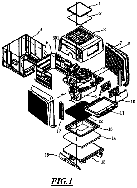
Rotisserie air-fryer oven
An air-fryer oven with a motorized rotating cage inside, so food tumbles in the hot air for even cooking.
US 11,085,657 B2 · Title as filed: Humidifier and float block for humidifier · Inventors: Chen; Ganlin
Sheet 1 of 4 from the published document. All sheets in the USPTO PDF
A humidifier whose float block inside the tank regulates flow through the air channel.
A humidifier and a float block for the humidifier are provided. The humidifier includes a water tank and a base. The water tank is located on the base. An air channel is arranged inside the water tank. A lower end of the air channel communicates with a blower installed inside the base. A mist passage chamber is vertically in the water tank. An upper end of the air channel communicates with an upper end of the mist passage chamber via a mist guide tube. The float block is arranged to float up and down inside the mist passage chamber. An atomizer corresponding to the mist passage chamber is installed at a lower end of the water tank.
The first 3 of 4 drawing sheets from the published document, cropped to the drawing. Every sheet is in the USPTO PDF.
Independent claims and the claims that build on them, read from each claim's text.
What the patent claimed, word for word. All of it is now free to use.
This application claims the priority benefit of China application serial no. 201710727510.2, filed on Aug. 23, 2017. The entirety of the above-mentioned patent application is hereby incorporated by reference herein and made a part of this specification. BACKGROUND Technical Field
The disclosure relates to the field of humidifiers, and in particular, to a humidifier and a float block for the humidifier. Description of Related Art
The humidifier is a small appliance commonly used in daily life. The humidifiers currently available generally do not exhibit a high efficiency in atomization of liquids, and the generated mist amount is often not large, which limits the effect of utilization of the humidifiers. To add water into the humidifiers currently available, the water tank must be picked up upside down, making the addition of water very inconvenient and also difficult to clean and easy to breed bacteria. In addition, in the humidifier currently available, the distance between the water surface of the water contained in the water tank and the atomizer at the bottom of the water tank cannot exceed a specific value. Otherwise, the mist amount generated will be very small due to the high water level in the humidifier currently available. As a result, the user must often add water because of the small amount of water that can be accommodated in the humidifier currently available.
The disclosure provides a humidifier and a float block for the humidifier that generate a larger mist amount and enhance the effect of utilization.
A humidifier of an embodiment of the disclosure includes a water tank and a base. The water tank is located on the base. An air channel is arranged inside the water tank. A lower end of the air channel communicates with a blower installed inside the base. A mist passage chamber is arranged in the water tank. An upper end of the air channel communicates with an upper end of the mist passage chamber via a mist guide tube. A float block is arranged to float up and down inside the mist passage chamber. An atomizer corresponding to the mist passage chamber is installed at a lower end of the water tank.
A float block of an embodiment of the disclosure is used in a humidifier. The float block includes an outer barrel that is hollow inside, and an inner float block is arranged to float inside the outer barrel.
In the humidifier and the float block for the humidifier of the embodiments of the disclosure, by applying a pressure to the liquid through the float block, a larger mist amount is generated and the effect of utilization is enhanced.
FIG. 1A is a perspective diagram illustrating a humidifier of the disclosure.
FIG. 1B is a perspective cross-sectional view illustrating a humidifier of the disclosure.
FIG. 2 is a perspective structural diagram illustrating a float block for a humidifier according to an embodiment of the disclosure.
FIG. 3 is a perspective structural diagram illustrating a float block for a humidifier according to another embodiment of the disclosure.
FIG. 4 is a cross-sectional diagram illustrating a use status of the float block of FIG. 3 installed in the humidifier.
The disclosure is further illustrated with reference to specific embodiments below. It is understood that the embodiments are merely meant to illustrate the disclosure rather than limit the scope of the disclosure. Moreover, it is also understood that, after reviewing the content taught in the disclosure, people skilled in the art may make various variations or modifications to the disclosure, and these equivalent forms similarly fall within the scope defined by the claims attached to the specification.
As shown in FIG. 1A and FIG. 1B , an embodiment of the disclosure relates to a top-fill humidifier 50 including a mist guide purification device. The humidifier 50 includes a water tank 1 and a base 5 . The water tank 1 is located on the base 5 . An air channel 14 is arranged inside the water tank 1 . A lower end of the air channel 14 communicates with a blower 2 installed inside the base 5 . Therefore, an air flow generated by the blower 2 can be conveyed to a top portion of the water tank 1 along the air channel 14 . A mist passage chamber 9 is arranged in the water tank 1 . An upper end of the air channel 14 communicates with an upper end of the mist passage chamber 9 via a mist guide tube 13 on a side. An atomizer 3 corresponding to the mist passage chamber 9 is installed at a lower end of the water tank 1 . A float block 8 having an opening in a middle portion is arranged to float up and down inside the mist passage chamber 9 . In other words, the float block 8 can move up and down inside the mist passage chamber 9 and is not fixed at a specific height inside the mist passage chamber 9 .
When in use, water or another liquid to be atomized is added into the water tank 1 . Then, the atomizer 3 starts to function and atomizes the liquid to be atomized in the mist passage chamber 9 . Mist moves upward along the mist passage chamber 9 to the top portion of the water tank 1 and then is discharged. Meanwhile, the blower 2 also starts to function, and the generated air flow is blown upward along the air channel 14 and enters the upper end of the mist passage chamber 9 via the mist guide tube 13 , which simultaneously drives blow of the mist to the outside and enhances the efficiency of mist discharge. Moreover, a pressure is applied to the liquid to be atomized through the float block 8 located in the mist passage chamber 9 , which enhances the efficiency of atomization of the liquid to be atomized by the atomizer 3 . In an actual operation, it was found that a mist amount generated by using the float block 8 was significantly increased as compared to a mist amount generated without using the float block 8 .
Optionally, a density of the float block 8 of the present embodiment may be smaller than the density of water. Therefore, the float block 8 can stay on the surface of the liquid to be atomized. In an actual operation, it was found that when the float block 8 stayed on the surface of the liquid to be atomized, the atomization efficiency of the atomizer 3 was further significantly enhanced.
In the present embodiment, a switch module 6 and a control circuit board 4 are installed on a sidewall on a side of the base 5 . The switch module 6 is configured to turn on/off the humidifier 50 , and the control circuit board 4 is configured to control operation statuses of the atomizer 3 , the blower 2 , and other components. Moreover, a float block positioning sleeve 17 is sleeved at the lower end of the mist passage chamber 9 to avoid direct contact between the float block 8 and the atomizer 3 . The air channel 14 can be vertically arranged on a side inside the water tank 1 , and the mist passage chamber 9 can be vertically arranged in a middle portion of the water tank 1 .
In the present embodiment, a filter part 7 having hollowed sidewalls is arranged to be outer to the lower end of the mist passage chamber 9 . A filter material 7 C is filled in the filter part 7 . For clarity of the drawings, the filter material 7 C is only shown in FIG. 1B . The filter part 7 includes, for example, a filter cover 7 A and a filter inner cover 7 B. The filter inner cover 7 B located on a bottom surface of the water tank 1 is arranged to be inner to a lower end of the filter cover 7 A. A filter inner chamber having hollowed sidewalls is formed between the filter inner cover 7 B and the filter cover 7 A, and the filter inner chamber is filled with the filter material 7 C. Such structure exhibits excellent filtering effect.
In the present embodiment, an upper lid 11 is installed at the upper end of the water tank 1 . A spray nozzle 12 located at the upper end of the mist passage chamber 9 is installed in a middle portion of the upper lid 11 . The mist can be blown to the outside via the spray nozzle 12 . The upper lid 11 can adequately block foreign matters such as dust in the environment from entering the water tank and prevent pollution of the liquid to be atomized. A water feed hole 16 is configured in an axial direction on sidewalls on two sides at the lower end of the mist passage chamber 9 to allow water feeding. One end of the mist guide tube 13 is connected to a separation board 10 vertically located at the upper end of the mist passage chamber 9 . The separation board 10 divides the upper end of the mist passage chamber 9 into two spaces and can prevent diffusion of the mist in the water tank 1 , which effectively enhances a humidification amount of the product.
As shown in FIG. 2 , the float block 8 of the present embodiment includes a barrel 81 having an opening in a middle portion. Guide circular plates 82 matching an inner diameter of the mist passage chamber 9 of FIG. 1B are arranged at two ends in the axial direction of the barrel 81 . A mist guide through-hole 81 A is vertically arranged inside the barrel 81 such that the mist can move toward the upper end of the mist passage chamber 9 via the mist guide through-hole 81 A. With the guide circular plates 82 , the float block 8 can smoothly move in the mist passage chamber 9 without rotating easily. Multiple axial direction reinforcement plates 83 are arranged surrounding a circumference outside the barrel 81 , which contributes to structural reliability.
According to an embodiment of the disclosure, when in use, the upper lid 11 is opened, water or another liquid to be atomized is added into the water tank 1 , and the liquid to be atomized passes through the filter cover 7 A and the filter inner cover 7 B and then enters the mist passage chamber 9 via the water feed hole 16 . The liquid to be atomized pushes the float block 8 up such that the float block 8 floats on the water surface. Then, the atomizer 3 starts to function and atomizes the liquid to be atomized in the mist passage chamber 9 . The mist moves upward from the mist guide through-hole 81 A of the float block 8 and is discharged via the spray nozzle 12 . Meanwhile, the blower 2 also starts to function, and the generated air flow is blown upward along the air channel 14 and enters the upper end of the mist passage chamber 9 via the mist guide tube 13 , which simultaneously drives blow of the mist to the outside and enhances the efficiency of mist discharge. A pressure is applied to the surface of the liquid to be atomized through the float block 8 located in the mist passage chamber 9 , which enhances the efficiency of atomization of the liquid to be atomized by the atomizer 3 .
As shown in FIG. 3 and FIG. 4 , a float block 100 of another embodiment of the disclosure includes an outer barrel 110 that is hollow inside. An inner float block 120 is arranged to float up and down inside the outer barrel 110 . When the surface of the liquid to be atomized in the mist passage chamber 9 is low, the outer barrel 110 of the float block 100 may contact the float block positioning sleeve 17 or the atomizer 3 below, such that the outer barrel 110 cannot apply a pressure to the liquid to be atomized. However, since the outer barrel 110 further includes the inner float block 120 inside, even if the surface of the liquid to be atomized is low, the inner float block 120 can still stay on the surface of the liquid to be atomized and continue to apply a pressure to the liquid to be atomized without contacting the float block positioning sleeve 17 or the atomizer 3 below. Accordingly, the float block 100 of the present embodiment can still increase the mist amount generated by the humidifier even if the surface of the liquid to be atomized is low.
In the present embodiment, an opening is configured at a lower end of the outer barrel 110 . A mist guide through-hole 170 is vertically arranged inside the inner float block 120 . An upper mist guide hole 160 is arranged in the middle of a top portion at an upper end of the outer barrel 110 . The mist guide through-hole 170 and the upper mist guide hole 160 are both configured to allow the mist to pass. A hollowed part 140 is configured on sidewalls on two sides of the outer barrel 110 . A seal ring 130 is installed at the lower end of the outer barrel 110 . The seal ring 130 seals the inner float block 120 inside the outer barrel 110 . A connection plate 150 is vertically arranged in a middle portion of the hollowed part 140 to enhance an overall structural strength.
In the humidifier and the float block for the humidifier of the disclosure, by disposing the float block to apply a pressure to the liquid, a larger mist amount is generated and the effect of utilization is enhanced. When the filter part is disposed, the humidifier further exhibits purification and filtering functions, enhances purity of the mist, and is more hygienic. When the inner float block is disposed in the float block, the mist amount generated by the humidifier can still be increased even if the surface of the liquid to be atomized is low.
Fees are due 3.5, 7.5 and 11.5 years after grant. This patent expired on August 10, 2025, so the fee marked "not paid" was the one that went unpaid.
HUMIDIFIER AND FLOAT BLOCK FOR HUMIDIFIER
Filed Jun 2018 · published Feb 2019Humidifier and float block for humidifier
Filed Jun 2018 · granted Aug 2021Earlier publications, parents and continuations. None of them can still be enforced, or this patent would not be listed.
Prior art cited by the examiner or applicant. Useful when you check your own idea for novelty.
Names, summaries, modern angles and build ratings are Patent Yard's editorial notes. Everything else on this page comes from the documents linked above.