 Lapsed, fee not paid8 drawings
Vehicles & Drones · US 11,230,237 B1
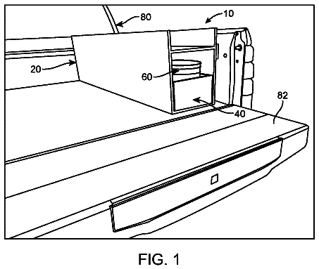
Truck bed tool drawer
A slide-out drawer toolbox with a built-in bucket that mounts in a vehicle.
US 11,084,516 B2 · Title as filed: Hydraulic helm pump with integrated electric pump · Inventors: Shannon; David Thomas
Sheet 1 of 10 from the published document. All sheets in the USPTO PDF
A hydraulic steering helm with its own electric pump, so an autopilot can steer without a separate pump installed.
A steering assembly for a hydraulic steering system is disclosed. The steering assembly includes a steering input device and an auxiliary drive assembly. The auxiliary drive assembly includes a lock valve body with one or more fluid passages that facilitates regulation of a fluid flow in response to an input from the steering input device. The lock valve body has a surface and a guide bore. Further, an electric pump is included that has an electric motor with a drive train unit. The electric pump is adapted to be mounted to the surface and the drive train unit is adapted to be positioned through the guide bore and operably coupled to the one or more fluid passages to regulate the fluid flow in the one or more fluid passages.
Manual hydraulic steering systems in watercrafts conventionally use a manual steering pump, such as an axial piston pump (also referred to as helm pumps), to power the watercraft's steering operation. Such systems generally include a steering input device and a rudder, with the manual steering pump typically operatively arranged between the steering input device and an actuator. The actuator, in general, embodies a steering cylinder, and is typically arranged between the manual steering pump and the rudder. The actuator is adapted to transfer a motion developed by the steering pump, in response to an input from the steering input device, to the rudder. For example, a movement (or rotation) of the steering input device, such as by manual or other powered means, enables a rotation of the steering pump, in turn facilitating the rudder's movement and the watercraft's steering operation. In f
The first 3 of 10 drawing sheets from the published document, cropped to the drawing. Every sheet is in the USPTO PDF.
Independent claims and the claims that build on them, read from each claim's text.
What the patent claimed, word for word. All of it is now free to use.
The present disclosure relates to a steering assembly in hydraulic steering systems in watercrafts, and, more particularly, to helm pumps that are integrated with an electric pump that is configured to drive the watercraft in an auto-mode or a power assist mode.
Manual hydraulic steering systems in watercrafts conventionally use a manual steering pump, such as an axial piston pump (also referred to as helm pumps), to power the watercraft's steering operation. Such systems generally include a steering input device and a rudder, with the manual steering pump typically operatively arranged between the steering input device and an actuator. The actuator, in general, embodies a steering cylinder, and is typically arranged between the manual steering pump and the rudder. The actuator is adapted to transfer a motion developed by the steering pump, in response to an input from the steering input device, to the rudder. For example, a movement (or rotation) of the steering input device, such as by manual or other powered means, enables a rotation of the steering pump, in turn facilitating the rudder's movement and the watercraft's steering operation.
In further detail, a transmission of motion between the steering input device and the steering pump is commonly imparted mechanically, such as by a power transmission shaft, as is conventionally known. A subsequent transmission of a motion from the steering pump to the rudder is mostly imparted by fluid pressure and flow. In general, fluid pressure may be built-up by the rotation of the steering pump, and once the fluid pressure is appropriately built-up, the fluid pressure (or flow) is translated to the steering cylinder for an actuation of the steering cylinder. Since the rudder is connected to the steering cylinder, an actuation executed by the steering cylinder (owing to a resulting pressure differential developed by increasing the fluid pressure in the steering pump) is translated to a motion of the rudder. A rudder motion facilitates the watercraft's steering, as aforementioned.
When adding an autopilot to a watercraft equipped with a conventional manual hydraulic steering system, an electric reversing pump is required to be integrated into the conventional manual hydraulic steering system. However, electric pumps need to be positioned suitably within the watercraft's hood or hull to comply with spatial constraints of the watercraft. Additionally, installation of electric pumps requires multiple hydraulic plumb lines and associated hydraulic fittings, which may increase cost and bulk of the hydraulic steering system. In general, it is also required to purge all of the additional plumb lines and fittings of air after initial assembly, and also after any service or repairs. This involves labor, time, and associated costs.
U.S. Pat. No. 5,357,889 (889 reference) to Robert A. R. Wood relates to an autopilot actuator in a watercraft. The '889 reference discloses an arrangement between a wheel shaft extension and a pusher shaft that causes the wheel shaft extension to turn in response to a system of gears activated by an electric motor. A turning of the wheel shaft extension activates a gear system within an associated rotary helm unit that moves the watercraft's rudder. The '889 reference works without hydraulic power, and, therefore, the '889 reference is silent on the use of electric hydraulic pumps.
One aspect of the present disclosure discusses a steering assembly for a hydraulic steering system. The steering assembly includes a steering input device and an auxiliary drive assembly. The auxiliary drive assembly includes a lock valve body and an electric pump. The lock valve body includes one or more fluid passages that facilitate regulation of a fluid flow in response to an input from the steering input device. The lock valve body includes a surface and a guide bore. The electric pump includes an electric motor with a drive train unit. The electric motor is configured to be mounted to the surface and the drive train unit is configured to be positioned through the guide bore and be coupled to the fluid passages to selectively regulate the fluid flow in the one or more fluid passages.
Certain aspects of the present disclosure disclose an auxiliary drive assembly for a hydraulic steering system. The auxiliary drive assembly includes a lock valve body with a recess and a guide bore. The lock valve body includes at least two input ports to alternatively receive fluid as input, at least two delivery ports to alternatively deliver fluid as output, a fluid passage defined between the at least two delivery ports, and a first spool valve configured to regulate a fluid flow from the at least two input ports to the at least two delivery ports. Further, an electric pump is included. The electric pump includes an electric motor with a drive train unit. The electric motor is configured to be received into the recess and the drive train unit is configured to be positioned through the guide bore and be coupled to the fluid passage to regulate the fluid flow between each of the at least two delivery ports.
In another aspect of the present disclosure a watercraft is disclosed. The watercraft includes a steering assembly with a steering input device and a helm pump. The helm pump is configured to be actuated by an input of the steering input device. Further, the hydraulic steering system includes an auxiliary drive assembly. The auxiliary drive assembly includes a lock valve body and an electric pump. The lock valve body is fluidly coupled to the helm pump and includes one or more fluid passages that facilitate regulation of a fluid flow in response to the input from the steering input device. The lock valve body includes a surface and a guide bore. The electric pump includes an electric motor with a drive train unit. The electric motor is configured to be mounted to the surface and the drive train unit is configured to be positioned through the guide bore and be coupled to the fluid passages, so as to selectively regulate the fluid flow in the one or more fluid passages.
FIG. 1 is a schematic view of a watercraft installed with a marine propulsion system and hydraulic steering system, in accordance with an embodiment of the present disclosure;
FIG. 2 is a steering circuit of the hydraulic steering system, in accordance with an embodiment of the present disclosure;
FIG. 3 is an assembled view of the steering assembly of FIG. 2 , in accordance with an embodiment of the present disclosure;
FIG. 4 is an isometric view of an exploded steering assembly of the hydraulic steering system of FIG. 3 , in accordance with an embodiment of the present disclosure;
FIGS. 5 and 6 are respective top and side views of the steering assembly, in accordance with an embodiment of the present disclosure; and
FIGS. 7, 8, 9, and 10 , are sectional views 7 - 7 , 8 - 8 , 9 - 9 , and 10 - 10 , of the steering assembly respectively, as has been disclosed in FIGS. 5 and 6 , in accordance with an embodiment of the present disclosure.
Reference will now be made in detail to preferred embodiments of aspects of the present disclosure, an example of which is illustrated in the accompanying drawings. Wherever possible, the same reference numerals will be used throughout the drawings and description to refer to the same or like parts.
Referring to FIG. 1 , there is shown an exemplary watercraft 100 . The watercraft 100 includes a steering system 102 and a marine propulsion system 104 . As part of the marine propulsion system 104 , the watercraft 100 includes an engine 106 , a power transmission unit (referred to as a pod 108 ), and a propeller 110 .
The engine 106 may be one of the commonly available power generation units of the art, such as embodying conventional internal combustion engines. In an embodiment, the engine 106 may embody a diesel engine or a petrol engine, although various other engine types are possible. The engine 106 may be located in an engine compartment (not shown) of the watercraft 100 . The engine 106 may embody an inline or a V-configuration, although other configurations are possible. The engine 106 may be connected to the pod 108 , which is inclusive of generally a complex arrangement of gearings, known power transmission units, and associated features, through a driveshaft (not shown). The connection between the engine 106 and the pod 108 may represent a first part connection. A second part connection may be represented by a connection between the pod 108 and the propeller 110 . The second part connection may be enabled through an auxiliary driveshaft 114 . Perhaps, a direct connection may exist between the pod 108 and the propeller 110 and may be known, understood, and applied, by those of skill in the art. The second part connection may be external of a transom 116 of the watercraft 100 and may be driven by the pod 108 to power the propeller 110 , facilitating watercraft propulsion. Effectively, the engine 106 , the pod 108 , and the steering system 102 , may work in concert to facilitate watercraft navigation in water. Although the configuration described, it may be noted that aspects of the present disclosure is not limited to the present disclosure alone, and varied environments, such as involving ‘all electric outboard motors’, may also use one or more of the disclosed aspects.
The steering system 102 is a hydraulic steering system. The steering system 102 is configured to steer and direct a motion of the watercraft 100 in water, such as when the marine propulsion system 104 is in operation. The steering system 102 includes a steering assembly 120 , a steering circuit 122 of the steering assembly 120 , a steering cylinder 124 , and a rudder 126 . The steering assembly 120 is comprised of a steering input device 130 , a manual or a helm pump 132 , and an auxiliary drive assembly 134 (best shown and envisioned in FIG. 6 ). The auxiliary drive assembly 134 in turn includes a lock valve body 136 and an electric pump 138 (see FIG. 2 , each of which will be discussed in detail later).
Referring to FIG. 3 , the steering circuit 122 ( FIG. 1 ) is formed by interlaid components namely the helm pump 132 , the lock valve body 136 , and the steering cylinder 124 . To this end, each of these components are fluidly coupled to each other by way of fluid lines 142 , constituting a rather busy design that follows a general practice of the art. Moreover, the fluid lines 142 (represented by a first fluid line 144 and second fluid line 146 ) are interconnected between said components in a manner so as to impart a two-way fluid flow between each of the helm pump 132 , the lock valve body 136 , and the steering cylinder 124 .
Referring to FIGS. 3 and 4 , the steering input device 130 may be a steering wheel, although it is possible for the steering input device 130 to represent control levers, joysticks, etc., as well. The steering input device 130 may be arranged in an operator station 150 of the watercraft 100 , such as within a dashboard 152 or a centre console of the watercraft 100 . Such dashboards may include one or more control input devices alongside the steering input device. In an embodiment, the steering input device 130 and control input devices may be configured to communicate with one or more onboard controllers (not shown) of the watercraft 100 to perform various functionalities of the watercraft 100 . For example, when the watercraft 100 is being operated in an auto steer mode, communication between the input devices and the onboard controller may be carried out. In an embodiment, such controllers may also include automatic control input devices such as open-loop controllers, closed-loop controllers, or programmable logic controllers. When in auto steer mode, the steering input device 130 may be used to override the automatic operations, for example, to make corrections outside of a programmed path. Additionally, remote control input devices such as wired or wireless telemetry devices, displays, combinations thereof, or any other control device known in the art, may also be contemplated. In an embodiment, the controller may include Global Positioning System (GPS) modules installed within that allows the watercraft 100 to be steered according to co-ordinates decided by a satellite, such as in the case of the auto steer mode of the watercraft 100 .
The steering input device 130 is configured to move/rotate between a left position and a right position, such as relative to the dashboard 152 (see arrows, L and R, FIG. 2 ). These denotations have been marked for ease in visualization and understanding. Moreover, these positions represent conventional steering positions and movement patterns that may be configured to alter a steering course of any conventional watercraft (such as watercraft 100 ), during operation. In an exemplary embodiment, if an operator moves the steering input device 130 to the right (arrow, R), fluid from the helm pump 132 is adapted to be released via the first fluid line 144 , actuate the steering cylinder 124 in direction, A, so as to alter a direction of the rudder 126 and execute a watercraft turn along a direction that generally corresponds to the direction represented by arrow, R. Similarly, if the steering input device 130 is moved to the left (arrow, L), fluid from the helm pump 132 is adapted to be released via the second fluid line 146 , actuate the steering cylinder 124 in direction, B, so as to alter a direction of the rudder 126 and execute a watercraft turn along a direction that generally corresponds to the direction represented by arrow, L. While fluid is released from the first fluid line 144 and the second fluid line 146 in each of these instances, fluid is also respectively received by the helm pump 132 via the other of first fluid line 144 and the second fluid line 146 .
Referring back to FIG. 2 , the steering cylinder 124 may be one of the commonly known steering cylinders in the art. The steering cylinder 124 includes a piston-connecting rod arrangement 156 that is slidably positioned within a cavity (not shown) of the steering cylinder 124 . Said piston-connecting rod arrangement 156 is capable to reciprocate (direction, A and B) within the cavity of the steering cylinder 124 across a length of the steering cylinder 124 . Such a movement may depend upon a direction of the fluid flow as and when received/released from the lock valve body 136 . Portions of the cavity defined across an associated piston (not shown) form the first chamber and the second chamber of the steering cylinder 124 , as known to those of skill in the art. The steering cylinder 124 may be an “inboard cylinder” type, which has a cylinder barrel axially fixed, while an associated cylinder rod may extend and retract relative to the cylinder barrel. Conversely, the steering cylinder 124 may have the cylinder rod fixed and the cylinder barrel axially movable relative to the cylinder rod. Using the latter cylinder type, may reverse the above noted description of the directions (see arrows, L and R, FIG. 2 ). Both the chambers are fluidly coupled to the lock valve body 136 via the first fluid line and 144 the second fluid line 146 , so as to selectively receive and deliver fluid from/to, or facilitate a two-way fluid communication with the lock valve body 136 . During operation, while one of the chamber is configured to receive fluid in response to an input from the steering input device 130 , the other is configured to release fluid back into the steering circuit 122 and the helm pump 132 . The steering cylinder 124 includes a first end 162 and a second end 164 , and although variations to this design is possible, the steering cylinder 124 is configured to receive/release fluid from each of the first end 162 and the second end 164 , via the fluid lines 144 , 146 , upon steering actuation.
Referring back to FIG. 1 , the rudder 126 is connected to the piston-connecting rod arrangement 156 (see FIGS. 1 and 2 in combination) and is able to move according to a movement executed by the piston-connecting rod arrangement 156 . In that way, the rudder 126 is powered by a movement of the piston-connecting rod arrangement 156 . The rudder 126 is connected to the piston-connecting rod arrangement 156 via a complex set of linkages (not shown for clarity) that operate in concert and in response to an input from the steering input device 130 or the electric pump 138 , such as when requested by an operator. Operator requests may include either of a manual input or an autopilot or a jog lever based input. Also, the set of linkages may embody mechanical rods, links, or cables.
Referring back to FIGS. 3 and 4 , the helm pump 132 is a hydraulic helm pump, although other hydraulic pumps may be contemplated. The helm pump 132 is operably connected to the steering input device 130 such that the helm pump 132 may respond to the movement (left and right positions) received as input from the steering input device 130 . The helm pump 132 may be a variable displacement pump. Moreover, the helm pump 132 may be an axial piston pump of a swashplate type, with a swashplate (not shown) that is fixedly connected to the steering input device 130 via a pump shaft 168 ( FIG. 4 ), such that a movement/rotation of the steering input device 130 may result in a movement/rotation of the swashplate. The helm pump 132 may be attached inwardly to the dashboard 152 of the watercraft 100 . The pump shaft 168 may be projected outwardly so as to be connected to the steering input device 130 , as is conventionally known. In that way, the steering input device 130 may remain accessible to an operator stationed in the operator station 150 .
In an embodiment, the helm pump 132 may include a wobbling swashplate, a cylinder block, and a number of pistons (not shown) that reciprocate within compression cylinders of the cylinder block, relative to a movement between the wobbling swashplate and the cylinder block (not shown). The helm pump 132 includes a back panel 170 and may house a commutator valve 172 , for example, to transmit fluid housed within the helm pump 132 to the lock valve body 136 upon operator request (such as by actuation of the steering input device 130 to either of the left or right positions). The helm pump 132 may be configured to alternate delivery of a fluid flow based on an input from the steering input device 130 , such as by advancing a flow from one portion of the helm pump 132 , while receiving a flow from another, so as to hydraulically affect an alternation between swayed positions of the rudder 126 . In so doing, the helm pump 132 facilitates watercraft steering. As an example, if the operator shifts the steering input device 130 to the left (arrow, L), corresponding pistons within the compression chamber of the helm pump 132 may compress against a fluid housed within the helm pump 132 . As a result, said fluid may be pushed out from the helm pump 132 to the lock valve body 136 , and then from the lock valve body 136 all the way to the steering cylinder 124 via the first fluid line 144 . A movement of the piston-connecting rod arrangement 156 may move to affect a movement of the rudder 126 and enable watercraft steering.
In the forthcoming description, the term ‘forward’ may be applied for components, and portions of said components, as being directed outwards of the dashboard 152 towards an operator input region (i.e. from where an operator may access the steering input device, such as the operator station 150 ). Similarly, ‘rearward’ may be applied to any component, or portions of said components, that are directed away from the operator input region.
The helm pump 132 includes a transfer plate 176 . The transfer plate 176 includes a first end 178 and a second end 180 . In assembly, the first end 178 faces a forward direction, and is connected to the back panel 170 which is rearward of the helm pump 132 . The second end 180 of the transfer plate 176 is connected to a forward face 184 of the lock valve body 136 . The transfer plate 176 may include inbuilt fluid ports 186 , and thereby facilitate fluid connection between the helm pump 132 and the lock valve body 136 . The transfer plate 176 may be connected to the back panel 170 via threaded fasteners 188 , such as by bolts and screws, as shown, and may be in turn be connected to the lock valve body 136 by being fastened at alternate locations via similar fastening means. In order to enable a secure transmission of fluid and prevent fluid leakage from between the helm pump 132 and the lock valve body 136 , multiple O-ring seals 190 may be provided at the associated interfacial connection portions formed by the transfer plate 176 with both the helm pump 132 and the lock valve body 136 , as shown. Known components such as washers, and the like, may also be included. To this end, grooves, and the like, may be defined on one or more associated fastening locations of the helm pump 132 , the transfer plate 176 , and the lock valve body 136 , to receive the O-ring seals 190 .
The steering system 102 is configured to operate in manual mode and an auto steer mode, as aforementioned. To this end, the lock valve body 136 and the electric pump 138 of the auxiliary drive assembly 134 are in abutment, and are operably integrated and interconnected with each other (discussed in detail further below). To attain a manual mode of operation of the steering system 102 , the steering input device 130 may operate in conjunction with the lock valve body 136 alone. However, to attain an auto steer mode of operation, the lock valve body 136 and the electric pump 138 may function in concert with each other when an input from the steering input device 130 is absent. In particular, the electric pump 138 may be configured to provide fluid housed within the lock valve body 136 with a requisite amount of fluid pressure in a desired direction to replicate an operational intent of the steering input device 130 . Additionally, in either of the manual mode or the auto steer mode, each of said components are tasked to either translate a motion of the steering input device 130 or of the electric pump 138 to a movement of the rudder 126 by fluid power, as will be elaborated further below.
The lock valve body 136 embodies a dual lock valve configuration and includes an inner configurations with multiple fluid inflow ports and fluid outflow ports. Out of the multiple inflow and outflow ports, at least two input ports 194 and at least two delivery ports 196 (see FIGS. 8 and 9 ) are included in the lock valve body 136 , although higher or a lesser number of ports 194 , 196 may be contemplated depending upon flow requirements of an associated operation. The input ports 194 are structured and arranged towards the forward face 184 of the lock valve body 136 , while the delivery ports 196 are structured and arranged towards a rearward face 198 of the lock valve body 136 . Further, the lock valve body 136 includes one or more fluid passages that facilitate a passage of fluid across the lock valve body 136 (such as from the input ports 194 to the delivery ports 196 ). By way of the ports 194 , 196 , the fluid passages, and a set of other components, such as valves (discussed later) within the lock valve body 136 , the lock valve body 136 is configured to regulate a fluid flow in response to an input received from either of the steering input device 130 or the electric pump 138 , and deliver the fluid to the steering cylinder 124 for an actuation of the rudder 126 .
Referring to FIGS. 5 and 6 , the steering assembly 120 is shown from varied view angles. More particularly, FIG. 5 is shown to include a top view of the steering assembly 120 , while FIG. 6 is shown to include a side view of the steering assembly 120 . FIGS. 5 and 6 also depict a variety of sections that are reproduced in following figures (namely FIGS. 7, 8, 9, and 10 ) to better understand an inner form, shape, and structure of the fluid passages, ports, associated flow directions, and various other configurational aspects of the lock valve body 136 .
Referring to FIGS. 2, 3, 4, and 5 , a construction of the lock valve body 136 is described. The lock valve body 136 embodies a generally cuboidal shape, with lateral faces (first lateral face 202 and second lateral face 204 , see FIGS. 2, 3, 4, and 5 ) on either sides that define curved contours, such as having a curvature starting from a top face 206 (represented as an upper surface along an elevation) of the lock valve body 136 and ending at a bottom face 208 along an elevation of the lock valve body 136 , as shown in FIG. 7 . Such a characteristic shape may allow the lock valve body 136 to be efficiently accommodated behind/within confinements available rearward of the dashboard 152 or the centre console (see FIG. 1 ).
Referring to FIGS. 7, 8, 9, and 10 , input ports 194 are structured within the lock valve body 136 such that the input ports 194 are revealed at the forward face 184 , while delivery ports 196 are structured within the lock valve body 136 such that the delivery ports 196 are revealed at the rearward face 198 . Although the nomenclature of the input ports 194 and the delivery ports 196 , a function associated with each of the input ports 194 and the delivery ports 196 may also include receiving the fluid from the steering cylinder 124 to be eventually delivered to the helm pump 132 , and thus the delivery ports 196 and the input ports 194 may be well configured to perform reverse functionalities as well (i.e. to receive fluid from the steering circuit 122 ). The input ports 194 are extended into the lock valve body 136 such that a common plane is defined therebetween. Similarly, the delivery ports 196 are also extended into the lock valve body 136 such that a similar common plane is defined therebetween. The planes of the input ports 194 and the delivery ports 196 are defined with an offset to each other, along an elevation of the lock valve body 136 . Said planes may be parallel to each other as well. In particular, the plane of the input ports 194 may be higher in elevation than the plane of the delivery ports 196 , as may be envisioned by viewing section 9 - 9 (or FIGS. 6 and 9 together). Nevertheless, it may be contemplated in certain alternatives that the input ports 194 and the delivery ports 196 are defined along a common plane, as well. Although not limited, planes of the input ports 194 and the delivery ports 196 are parallely defined relative to the top face 206 and the bottom face 208 .
The input ports 194 and the delivery ports 196 are exemplarily two in number, while it is possible that additional ports may be included that serve alongside said ports 194 , 196 . In general, the input ports 194 are represented by a first input port 194 ′ and a second input port 194 ″, as shown. Similarly, the delivery ports 196 are represented by a first delivery port 196 ′ and a second delivery port 196 ″. The input ports 194 are configured to receive fluid as input from the helm pump 132 . This fluid is transmitted via connecting passages 218 (see FIG. 9 ), depending upon a direction of rotation of the steering input device 130 , to the delivery ports 196 . Based on such a receipt, the delivery ports 196 are configured to deliver fluid from the lock valve body 136 , as an output, to the steering cylinder 124 for steering actuation. Such a flow path of fluid is also reversible, for example when the steering input device 130 is rotated in reverse to the above direction. In operation, when the first input port 194 ′ receives fluid flow from the helm pump 132 in response to an input of the steering input device 130 , the second input port 194 ″ returns a fluid flow to the helm pump 132 , and similarly, as an input of the steering input device 130 facilitates release of a fluid flow into the second input port 194 ″, a fluid flow may be received by the helm pump 132 via the first input port 194 ′. In all instances, fluid delivered by an actuation of the steering input device 130 releases fluid along one fluid line 144 , 146 and receives fluid from the other fluid line 144 , 146 , effectively defining a closed-loop hydraulic system. Exemplarily, a fluid released by an input of the steering input device 130 when transmitted to the first (or second) input port 194 ′, 194 ″, further flows down into the first (or second) delivery port 196 ′, 196 ″ and flows out all the way to one end of the steering cylinder 124 to affect the steering cylinder's actuation. Simultaneously, a fluid flow returns from the steering cylinder 124 to the lock valve body 136 via the second (or first) delivery port 196 ″, 196 ′ and all the way to the helm pump 132 via the second (or first) input port 194 ″, 194 ′. A similar fluid flow is envisioned when the electric pump 138 is used to apply fluid pressure (discussed below).
Further, multiple bores 210 are structured within the lock valve body 136 . The bores 210 are exemplarily two in number (first bore 210 ′ and second bore 210 ″) each of which is adapted to accommodate a spool valve 212 that is pilot operated. The spool valve 212 is representative of a first spool valve 212 ′ and a second spool valve 212 ″. The spool valve 212 is a double acting—pilot operated check valve. The bores 210 are structured so as to extend transversally to the lock valve body 136 , such as from the first lateral face 202 and the second lateral face 204 . In that way, the bores 210 are substantially perpendicular to the delivery ports 196 and the input ports 194 in layout. The first bore 210 ′ is positioned in closer proximity and in fluid communication with the input ports 194 while the second bore 210 ″ is positioned in closer proximity and fluid communication with the delivery ports 196 (see FIGS. 8 and 9 ). The bores 210 are structured and arranged serially relative to each other with the second spool valve 212 ″ being positioned towards the rearward direction of the steering system 102 . A plane defined by the disposal of the bores 210 is parallel to the planes defined by the delivery ports 196 and the input ports 194 . Variations to this configuration is possible such as by having the plane of the bores 210 being positioned at an angle to either of the planes of the delivery ports 196 or the input ports 194 . Further, each of the bores 210 may include an end fitting 216 arranged at either ends of the bores 210 . In an example, the end fitting 216 may threadably coupled to either ends of the bores 210 and may include hex key slots by which the end fitting 216 may be tightened into outwardly revealed openings on the lateral faces 202 and 204 of the bores 210 .
One or more fluid passages are structured within the lock valve body 136 connecting said bores 210 ′, 210 ″ to each other. In general, one or more of the fluid passages facilitate a fluid flow between the input ports and the delivery ports. The first bore 210 ′ is in selective fluid communication with the input ports 194 , as facilitated by the first spool valve 212 ′, and the second bore 210 ″ is in fluid communication with the delivery ports 196 , as facilitated by the second spool valve 212 ″. Connecting passages 218 (a first connecting passage 218 ′ and a second connecting passage 218 ″) are provided within the lock valve body 136 at a generally higher elevation in relation to the plane of the bores 210 and the ports 194 , 196 (see FIGS. 6, 8 , and 9 in combination). In particular, the first connecting passage 218 ′ is in selective fluid communication with the first input port 194 ′, while the second connecting passage 218 ″ is in selective fluid communication with the second input port 194 ″, as facilitated by the first spool valve 212 ′.
However, the first connecting passage 218 ′ is in lasting fluid communication with the first delivery port 196 ′ and the second connecting passage 218 ″ is in lasting fluid communication with the second delivery port 196 ″, as facilitated by by-passing the second spool valve 212 ″. In that way, the connecting passages 218 , by way of the first spool valve 212 ′, facilitate a regulation of fluid released and received into the helm pump 132 via the input ports 194 , by-passing any form of regulation from the second spool valve 212 ″ during operation. Such an operational parameter constitutes a manual mode of watercraft operation, and an operation of which will be discussed later.
Referring to FIG. 10 , and as part of the one or more fluid passages, a pair of upright fluid passages 222 (represented by a first upright passage 222 ′ and a second upright passage 222 ″) are fluidly coupled and extended from the second bore 210 ″ along an elevation, E, of the lock valve body 136 . The upright fluid passages 222 are perpendicularly defined to the second bore 210 ″. Openings of the upright fluid passages 222 are revealed at the top face 206 of the lock valve body 136 . A plane defined by the upright fluid passages 222 is perpendicular to the planes of the delivery ports 196 and the input ports 194 , although allowable variations may be contemplated. The upright fluid passages 222 are in selective fluid communication with the delivery ports 196 as facilitated by the second spool valve 212 ″. The upright fluid passages 222 , second spool valve 212 ″, second bore 210 ″, in combination with the delivery ports 196 , are in concert configured to facilitate transmission of fluid during an auto mode of watercraft operation.
Referring to FIG. 8 , details of the spool valve 212 will now be discussed. Collectively, an assembly of the spool valve 212 (such as the first spool valve 212 ′) within the bores 210 (such as the first bore 210 ′) is referred to as a spool valve arrangement 224 (such as a first spool valve arrangement 224 ′—while the corresponding second spool valve arrangement being referred as second spool valve arrangement 224 ″). Given the lateral disposal of the bores 210 relative to the lock valve body 136 , a disposal of the spool valve arrangements 224 ′, 224 ″ is also defined at right angles to both the delivery ports 196 and the input ports 194 . The first spool valve 212 ′ is adapted to block the connecting passages 218 from fluidly communicating with the input ports 194 . More specifically, in a default state of the first spool valve 212 ′, or in a neutral state of the steering input device 130 , a flow between the input ports 194 , the connecting passages 218 , and the delivery ports 196 is open, while a flow from the connecting passages 218 to the input ports 194 is blocked. Similarly, the second spool valve 212 ″ is adapted to block the delivery ports 196 from fluidly communicating with the upright fluid passages 222 , while a fluid flow from the upright fluid passages 222 to the delivery ports 196 , via the connecting passages 218 , is open, such as in a default state of the second spool valve 212 ″, and/or when the electric pump 138 is inactive.
The forthcoming description includes references focused towards the first spool valve arrangement 224 ′, unless specified otherwise. For clarity, details of only the first spool valve arrangement 224 ′ is marked and discussed. It will be understood that discussions directed towards the first spool valve arrangement 224 ′ will remain similar for the second spool valve arrangement 224 ″, as well.
The first spool valve 212 ′ has a first spool 213 ′ reciprocatingly received within the first bore 210 ′. The first spool 213 ′ has a first end 226 ′ and a second end 226 ″. The first end 226 ′ includes a first annular cylinder portion 227 ′, while the second end 226 ″ includes a second annular cylinder portion 227 ″. The first bore 210 ′ includes a first end portion 228 ′ adjacent to the first end 226 ′ and a second end portion 228 ″ adjacent to the second end 226 ″. The first end portion 228 ′ has a larger diameter than the first annular cylinder portion 227 ′ and a circumference (or an inner wall 230 ) that is slidingly and sealingly engaged with the first annular cylinder portion 227 ′. Similarly, the second end portion 228 ″ has a larger diameter than the second annular cylinder portion 227 ″ and a circumference (the inner wall 230 ) that is slidingly and sealingly engaged with the second annular cylinder portion 227 ″. A center portion 232 of the spool 213 ′ is structured between the first annular cylinder portion 227 ′ and the second annular cylinder portion 227 ″. The center portion 232 is smaller in diameter than the first annular cylinder portion 227 ′ and the second annular cylinder portion 227 ″, in turn defining an annular passageway 234 between the first annular cylinder portion 227 ′ and the second annular cylinder portion 227 ″, relative to the first bore 210 ′.
Also, first spool valve 212 ′ includes ball portions (first ball 240 ′, second ball 240 ″), which are respectively resiliently biased towards ball seats 236 ′, 236 ″ by compression springs 242 ′, 242 ″. Also, the balls 240 ′, 240 ″ are guided concentric with an axis of the first bore 210 ′ by the end fitting 216 of the first bore 210 ′. Further, compression springs 242 ′, 242 ″ of both the balls 240 ′, 240 ″ may include a spring force which is identical to each other. With both ends 226 ′, 226 ″ of the first spool 213 ′ being in selective engagement with the balls 240 ′, 240 ″, the first spool 213 ′ is biased towards a center of the first bore 210 ′, and, in that manner, a default state of the first spool valve 212 ′ is attained. A gap may respectively exist between ends 226 ′, 226 ″ of the first spool 213 ′ and the balls 240 ′, 240 ″ to ensure a seating. In this default state of the first spool valve 212 ′, a fluid flow between connecting passages 218 to outer zones 249 ′, 249 ″, further to a center zone 247 and to input ports 194 is blocked in the valve default state. In an embodiment, one (or both) of the spool valves arrangements (such as the second spool valve arrangement 224 ″) may include structural configurations and features in relation to a corresponding inner wall of the related bore (such as the second bore 210 ″) that ensure maintenance of a balance of fluid volume in the lock valve body 136 . For example, leak paths 243 ′, 243 ″ ( FIG. 8 ) may be provided adjacent the second spool valve arrangement 224 ″, in fluid communication with the second bore 210 ″, such that in strategic position of the second spool valve 212 ″ a quantity of fluid may be directed to a reservoir (not shown). Similar leak paths (not shown) may be present in the first spool valve arrangement 224 ′ as well. In general, the structure of the second spool valve arrangement 224 ″ and the balls 240 ′, 240 ″ is conventional and therefore is not described in further detail. In an embodiment, other types of one-way valves could be employed as well, such as poppet valves.
The description continues in the full USPTO document.
Fees are due 3.5, 7.5 and 11.5 years after grant. This patent expired on August 10, 2025, so the fee marked "not paid" was the one that went unpaid.
HYDRAULIC HELM PUMP WITH INTEGRATED ELECTRIC PUMP
Filed Sep 2016 · published Jun 2020Hydraulic helm pump with integrated electric pump
Filed Sep 2016 · granted Aug 2021Earlier publications, parents and continuations. None of them can still be enforced, or this patent would not be listed.
Prior art cited by the examiner or applicant. Useful when you check your own idea for novelty.
Names, summaries, modern angles and build ratings are Patent Yard's editorial notes. Everything else on this page comes from the documents linked above.